Difference between revisions of "Radio Frequency Counter UAS System"
Jump to navigation
Jump to search
| Line 21: | Line 21: | ||
[[File:DSM_2RFC.png|frameless|1000px]] | [[File:DSM_2RFC.png|frameless|1000px]] | ||
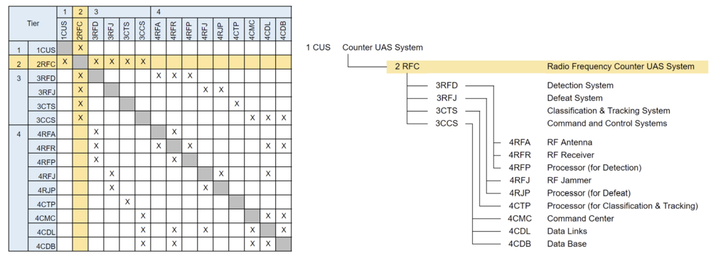
The above 2RFC tree shows the relationship between some systems related to the Counter UAS system that uses radio frequency as for detection and defeat. This tree says that the Counter UAS system consists of the detection system (3RFD), defeat system (3RFJ), classification & tracking system (3CTS), and command and control system (3CCS). In addition, these subsystems require several components such as an RF antenna (4RFA), RF jammer (4RFJ), a processor for classification and tracking (4CTP), command center (4CMC), and so on. As this DSM shows, The DSM indicates that each component is coupled to function as an RF counter UAS system. | |||
Revision as of 00:07, 10 October 2024
Roadmap Creators:
- [Sam Youngdale]
- [Chris Emerson]
- Jumpei Sakamoto
Time Stamp: 10 October 2024
Radio Frequency Counter UAS System
Roadmap Overview
DSM Allocation
This would be related to the following existing roadmaps:
The above 2RFC tree shows the relationship between some systems related to the Counter UAS system that uses radio frequency as for detection and defeat. This tree says that the Counter UAS system consists of the detection system (3RFD), defeat system (3RFJ), classification & tracking system (3CTS), and command and control system (3CCS). In addition, these subsystems require several components such as an RF antenna (4RFA), RF jammer (4RFJ), a processor for classification and tracking (4CTP), command center (4CMC), and so on. As this DSM shows, The DSM indicates that each component is coupled to function as an RF counter UAS system.
