Difference between revisions of "Variable Emissivity Materials For Spacecraft"
| (194 intermediate revisions by 2 users not shown) | |||
| Line 7: | Line 7: | ||
* '''4VEM - Variable Emissivity Materials for Spacecraft''' | * '''4VEM - Variable Emissivity Materials for Spacecraft''' | ||
Passive, thermochromic variable emissivity materials (VEMs) can be used for a wide range of applications, from spacecraft radiators to windows used on Earth. For this technology roadmap, the use of VEMs for spacecraft radiators will be the focus. | |||
==Roadmap Overview== | ==1. Roadmap Overview== | ||
The only way that orbiting spacecraft can reject heat is through radiation. Because of this, the thermo-optical properties of spacecraft radiators are important. The thermo-optical properties of radiators, such as emissivity, determine how much heat is radiated away. | The only way that orbiting spacecraft can reject heat is through radiation. Because of this, the thermo-optical properties of spacecraft radiators are important. The thermo-optical properties of radiators, such as emissivity, determine how much heat is radiated away. | ||
| Line 26: | Line 26: | ||
There are active (electrochromic) and passive (thermochromic) VEMs. Electrochromic VEMs require power input to change emissivity, unlike thermochromic VEMs which change their emissivity based on their temperature. The technology of thermochromic VEMs whose emissivity is lower at low temperatures and higher at high temperatures is expected to be widely used in radiators for spacecraft, because compared to constant-emissivity radiators, it reduces spacecraft heater power requirements and temperature swings, all without power or human input. Figure 1 shows how a thermochromic VEM can help spacecraft more efficiently manage their temperature. | There are active (electrochromic) and passive (thermochromic) VEMs. Electrochromic VEMs require power input to change emissivity, unlike thermochromic VEMs which change their emissivity based on their temperature. The technology of thermochromic VEMs whose emissivity is lower at low temperatures and higher at high temperatures is expected to be widely used in radiators for spacecraft, because compared to constant-emissivity radiators, it reduces spacecraft heater power requirements and temperature swings, all without power or human input. Figure 1 shows how a thermochromic VEM can help spacecraft more efficiently manage their temperature. | ||
[[File:howVEMsAffectSpacecraft.png|center]] | [[File:howVEMsAffectSpacecraft.png|center|800x600px]] | ||
<div style="text-align: center;"> | <div style="text-align: center;"> | ||
Figure 1: Diagram of how VEMs affect spacecraft, from [1] | Figure 1: Diagram of how VEMs affect spacecraft, from [1] | ||
</div> | </div> | ||
This roadmap will explore how thermochromic VEMs have evolved, their Figures of Merit, | This roadmap will explore how passive, thermochromic VEMs have evolved, their Figures of Merit, what is expected in the future, and the company's plans to develop VEM technology. | ||
==Design Structure Matrix (DSM) Allocation== | ==2. Design Structure Matrix (DSM) Allocation== | ||
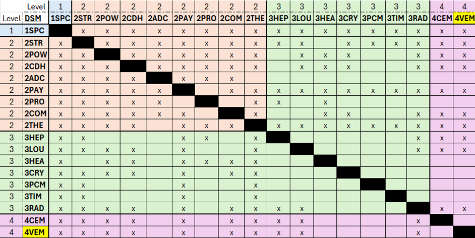
Figure 2 below shows the interactions between various technologies and the 4VEM variable emissivity technology. The x's in the matrix signify interaction. | |||
[[File:UpdatedUPDATEDDSMMatrixVEMs.png|center]] | |||
<div style="text-align: center;"> | <div style="text-align: center;"> | ||
Figure 2: DSM Matrix | Figure 2: DSM Matrix | ||
</div> | </div> | ||
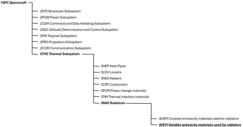
VEMs are part of a larger technology tree. Figure 3 below shows the technology tree. | |||
[[File:DSMtreeVEMs.png|center|800x600px]] | |||
* | <div style="text-align: center;"> | ||
Figure 3: 4VEM Technology Tree Placement | |||
</div> | |||
In the tree, the 1st level is the technology of a general spacecraft: | |||
* 1SPC Spacecraft | |||
The 1SPC Spacecraft technology has a variety of subsystem technologies; all of the subsystems of a spacecraft interact with each other and make the spacecraft work, and they make up the second level: | |||
* | * 2STR Structures Subsystem | ||
* | * 2POW Power Subsystem | ||
* | * 2CDH Command and Data Handling Subsystem | ||
* | * 2ADC Attitude Determination and Control Subsystem | ||
* | * 2PAY Payload Subsystem | ||
* | * 2PRO Propulsion Subsystem | ||
* | * 2COM Communication Subsystem | ||
* 2THE Thermal Subsystem. | |||
* | |||
VEMs are part of the 2THE thermal subsystem of a spacecraft. Many technologies are used for spacecraft thermal subsystems, and they are in the 3rd level: | |||
* 3HEP Heat Pipes | |||
* 3LOU Louvers | |||
* 3HEA Heaters | |||
* 3CRY Cryocoolers | |||
* 3PCM Phase-change materials | |||
* 3TIM Thermal interface materials | |||
* 3RAD Radiators | |||
VEMs are used in the 3RAD Radiators technology. The 3RAD technology can be split into two groups as well, which comprise the 4th level: | |||
* 4CEM Constant emissivity materials used for radiators | |||
* 4VEM Variable emissivity materials used for radiators. | |||
So, VEMs are a small part of the whole spacecraft technology. | |||
== 3. Roadmap Model using OPM == | |||
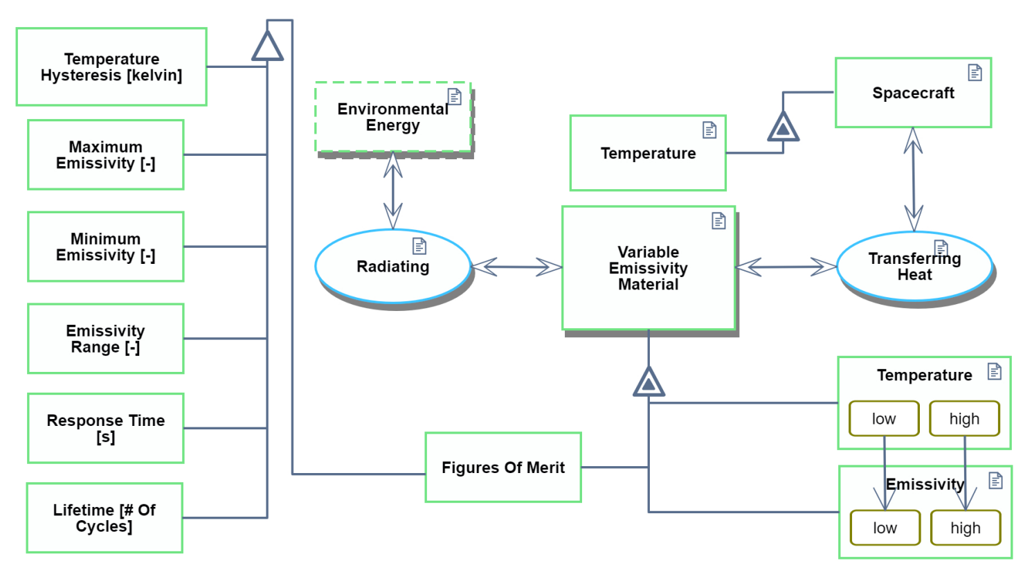
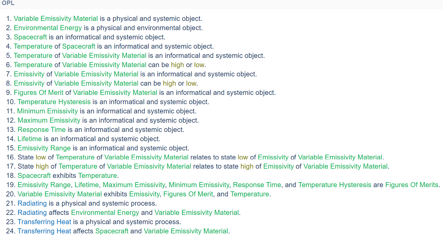
The Object-Process Diagram (OPD) and Object-Process Language (OPL) represented in Figure 4 and Figure 5, respectively, were generated by OPCloud. This model describes the processes and Figures of Merit (FOM) involved with passive spacecraft VEMs, as well as their object interactions. It highlights the thermochromic VEMs discussed in this roadmap, which require no electrical energy to operate. | |||
[[File:VEMOPM.png|center|800x600px]] | |||
<div style="text-align: center;"> | |||
Figure 4: VEM OPD | |||
</div> | |||
[[File:VEMOPL.png|center|800x600px]] | |||
<div style="text-align: center;"> | |||
Figure 5: VEM OPL | |||
</div> | |||
== 4. Figures of Merit (FOM) == | |||
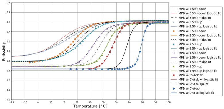
There are several Figures of Merit (FOMs) that describe VEMs. In order to describe the FOMs, an emissivity vs. temperature graph of several VEMs made from vanadium dioxide doped with tungsten will be shown in Figure 6, which is from [1]. | |||
[[File:EmissivityVersusTemperatureVEMs.png|center]] | |||
<div style="text-align: center;"> | |||
Figure 6: Emissivity versus Temperature for Some VEMs, from [1] | |||
</div> | |||
There are four types of VEMs shown in Figure 6; each VEM is made from vanadium dioxide doped with different percentages of tungsten. The first VEM is doped with 3.5% tungsten (the MPB W(3.5%) VEM), the second VEM is doped with 2.5% tungsten, the third VEM is doped with 1.5% tungsten, and the last VEM is doped with 0% tungsten. | |||
For each type of VEM, there is an up curve and a down curve. The up curve corresponds to the emissivity profile when the material is being heated up, and the down curve corresponds to the emissivity profile when the material is being cooled down. The logistic fit curve fits the data to a logistic equation, and the midpoint line is in between the up and down curves. | |||
Because there is a difference in the emissivity vs. temperature curves for when the material is being heated up and when the material is being cooled down, there is hysteresis. One FOM of VEMs is seeing how much hysteresis there is in the material. The less hysteresis, the better because it is easier and quicker to model VEMs with no hysteresis. | |||
One way to calculate the amount of hysteresis is to determine at what temperature the material is when emissivity is at its midpoint and compare that temperature between the heating curve and the cooling curve. So, for the MPB W(0%) down curve, the midpoint temperature <html><la-tex>T_{down}^\ast</la-tex> </html> is around 55 degrees Celsius; for the MPB W(0%) up curve, the midpoint temperature <html><la-tex>T_{up}^\ast</la-tex> </html> is around 80 degrees Celsius. So, the difference between <html><la-tex>T_{up}^\ast</la-tex> </html> and <html><la-tex>T_{down}^\ast</la-tex> </html> is a FOM, which will be called <html><la-tex>\Delta T_{hys}</la-tex> </html>. | |||
<div style="text-align: center;"> | |||
<html> | |||
<la-tex>∆T_{hys}=T_{up}^*-T_{down}^*</la-tex> | |||
</html> | |||
</div> | |||
For the MPB W(0%) curve, | |||
<div style="text-align: center;"> | |||
<html> | |||
<la-tex>∆T_{hys}=80-55 \; degrees \; C = 25 \; degrees \; C</la-tex> | |||
</html> | |||
</div> | |||
The lower <html><la-tex>\Delta T_{hys}</la-tex> </html> is, the less hysteresis. An increase in tungsten doping decreases hysteresis and <html><la-tex>\Delta T_{hys}</la-tex> </html> as shown in Figure 6. The nominal value of <html><la-tex>\Delta T_{hys}</la-tex> </html> is 0 degrees Celsius. | |||
There is also the minimum emissivity <html><la-tex>\varepsilon_L</la-tex> </html> and maximum emissivity <html><la-tex>\varepsilon_H</la-tex> </html> of a VEM. The minimum emissivity corresponds to when the material is relatively cold, and the maximum emissivity corresponds to when the material is relatively hot. The theoretical limit for minimum emissivity is an emissivity of 0, and the theoretical limit for maximum emissivity is an emissivity of 1. Engineers and scientists have generally been trying to make the minimum emissivity as close to 0 as possible and the maximum emissivity as close to 1 as possible. | |||
So, two FOMs are the minimum emissivity <html><la-tex>\varepsilon_L</la-tex> </html> and maximum emissivity <html><la-tex>\varepsilon_H</la-tex></html> of a VEM. For the MPB W(0%) midpoint curve, <html><la-tex>\varepsilon_L</la-tex> </html> is around 0.32, and <html><la-tex>\varepsilon_H</la-tex> </html> is around 0.8. | |||
Another FOM engineers and scientists have been using in analyzing VEM technology is the difference between the minimum emissivity <html><la-tex>\varepsilon_L</la-tex></html> and the maximum emissivity <html><la-tex>\varepsilon_H</la-tex> </html> of a VEM; this FOM, which is the tunability of the material, will be called <html><la-tex>\Delta\varepsilon</la-tex></html>. Engineers and scientists have been trying to maximize <html><la-tex>\Delta\epsilon</la-tex> </html> and trying to get <html><la-tex>\Delta\varepsilon</la-tex> </html> as close to 1 as possible; the nominal value for <html><la-tex>\Delta\varepsilon</la-tex> </html> is 1. | |||
<div style="text-align: center;"> | |||
<html> | |||
<la-tex>\Delta\varepsilon=\varepsilon_H-\varepsilon_L</la-tex> | |||
</html> | |||
</div> | |||
So, for the MPB W(0%) midpoint curve, with an <html><la-tex>\varepsilon_L</la-tex> </html> of around 0.32 and an <html><la-tex>\varepsilon_H</la-tex> </html> of around 0.8, | |||
<div style="text-align: center;"> | |||
<html> | |||
<la-tex>\Delta\varepsilon=0.8-0.32=0.48</la-tex> | |||
</html> | |||
</div> | |||
The closer <html><la-tex>\varepsilon_L</la-tex> </html>, <html><la-tex>\varepsilon_H</la-tex> </html>, and <html><la-tex>\Delta\varepsilon</la-tex> </html> are to their nominal values, the easier it should be for spacecraft to passively regulate their temperature. | |||
The table below presents the FOM that can be used to evaluate various VEMs, with the most important ones being the emissivity values and temperature hysteresis. | |||
{| class="wikitable" | |||
|- | |||
! Figure of Merit !! Units !! Description | |||
|- | |||
| Temperature Hysteresis (<html><la-tex>\Delta T_{hys}</la-tex></html>)|| [K] || This describes how large hysteresis is for the VEM, and it is a difference of temperatures. The smaller the quantity, the better. The nominal value is 0 Kelvin (or 0 degrees Celsius). | |||
|- | |||
| Minimum Emissivity (<html><la-tex>\varepsilon_L</la-tex></html>) || [-] || This is the minimum emissivity of a VEM. The nominal value is 0. | |||
|- | |||
| Maximum Emissivity (<html><la-tex>\varepsilon_H</la-tex></html>) || [-] || This is the maximum emissivity of a VEM. The nominal value is 1. | |||
|- | |||
| Emissivity Range (<html><la-tex>\Delta\varepsilon</la-tex></html>) || [-] || This is the difference between the maximum and minimum emissivities of VEMs. The nominal value is 1. | |||
|- | |||
| Lifetime (<html><la-tex>n</la-tex></html>) || [Cycles] || This is the number of emissivity state switches the material can undergo before failure. The higher this value, the better the VEM. | |||
|- | |||
| Response Time (<html><la-tex>t</la-tex></html>) || [s] || This is the amount of time it takes for the device to switch between different emissivity states. The lower the response time, the better the thermal control. | |||
|} | |||
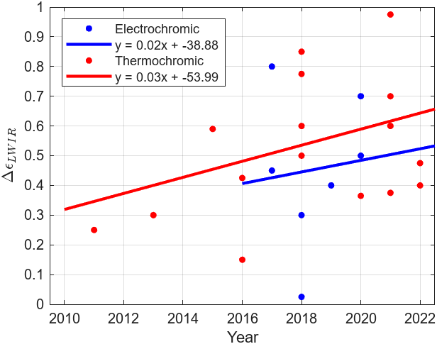
Figure 7 displays a diverse spread of variability in emissivity ranges for active and passive types of modern VEMs over time using data from [2] and [3], which also include the specific VEM technologies plotted. The distribution of the emissivity ranges is a reminder that emissivity range may not necessarily be the most important figure of merit for a specific VEM application, hence why there is not a clear upward trend in the data over time. Although the data is very disperse, linear regression models were applied, and they show an improvement for electrochromic and thermochromic VEMs of 0.02/year and 0.03/year, respectively. Due to physics principles, the theoretical emissivity range for a given material is 1, with the maximum emissivity being 1 and the minimum being 0. This cannot exceed 1 due to the law of conservation of energy. That it, an object cannot emit more than 100% of its energy. In terms of application to passive spacecraft thermal control, thermochromic VEMs are at the incubation stage of the technology lifecycle because very few VEMs have been sent to space. One VEM technology, Thermal Control Tiles designed by MPB Communications, was sent to space in the early 2020's [4][5], and the Air Force Research Laboratory launched a VEM experiment to the International Space Station (ISS) on November 4, 2024, to study how VEMs behave in low Earth Orbit outside of the ISS for a year [12]. | |||
[[File:VEMEmissivityRange.png|center]] | |||
<div style="text-align: center;"> | |||
Figure 7: Modern VEM Emissivity Ranges with Data Adapted from [2] and [3] | |||
</div> | |||
==5. Alignment with Company Strategic Drivers== | |||
Below is a table that has company strategic drivers, how they align with the roadmap, and targets for the company. | |||
{| class="wikitable" | |||
|- | |||
! Number !! Strategic Driver !! Alignment and Targets | |||
|- | |||
| 1 || To develop a commercially viable variable emissivity material that significantly reduces spacecraft heater power requirements and temperature swings and will generate profit for the company in the long term. || The 4VEM roadmap's goal is produce a variable emissivity material with an <html><la-tex>\varepsilon_H</la-tex></html> of 0.9, an <html><la-tex>\varepsilon_L</la-tex></html> of 0.075, and a temperature hysteresis of 2.5 [K]. This driver is currently aligned with the roadmap. | |||
|- | |||
| 2 || To develop commercially viable dust-mitigated variable emissivity radiators for spacecraft on the moon. Lunar dust greatly affects spacecraft radiators on the moon [7], so by incorporating dust mitigation technology into the company's variable emissivity materials, the market can expand to lunar spacecraft more easily.|| The target would be to develop a variable emissivity material that easily repels lunar dust. This driver is '''not''' currently aligned with the roadmap because the FOMs that are explored in this roadmap are not about how VEMs repel lunar dust. | |||
|} | |||
Strategic driver 1 and its targets are the main goal for the company's R&D department. The company will make investments to improve <html><la-tex>\varepsilon_H</la-tex></html>, <html><la-tex>\varepsilon_L</la-tex></html>, and the temperature hysteresis to make a VEM that can sell in a competitive market. | |||
One of NASA's main civil space technology shortfalls is surviving the lunar night [8], and having dust-mitigated VEMs will help spacecraft on the moon survive the night by decreasing heater power required. So, the company would like to eventually expand to create lunar dust-mitigated variable emissivity materials, but it will not be the main focus of the company currently; strategic driver 2 is not a requirement of this roadmap. | |||
==6. Positioning of Company versus Competition== | |||
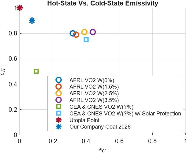
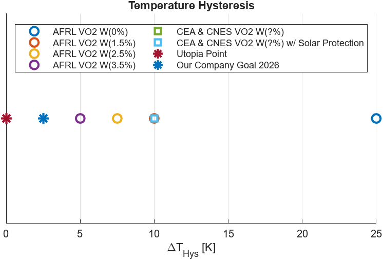
Figures 8 and 9 display the current FOM capabilities of several VEMs for passive spacecraft thermal control, including ones created by the Air Force Research Lab (AFRL) [1] and Commissariat à l’energie Atomique (CEA) & Centre National d'études Spatiales (CNES) [9]. Also included are the utopia points, or theoretical limits, of these FOMs. An ideal VEM will have an emissivity range of 1, with its hot-state emissivity = 1 (for maximum radiative heat transfer), and its cold-state emissivity = 0 (for minimum radiative transfer). An ideal VEM also has a temperature hysteresis = 0, meaning its emissivity vs temperature curve is not dependent on whether the material is heating up or cooling down. The goal for our company by 2026 is to make improvements to the current state-of-the-art materials by creating a VEM capable of achieving a hot-state emissivity = 0.9, a cold-state emissivity = 0.075, and a temperature hysteresis = 2.5 K. This will be achieved by extensive analyses, material selection, simulation, testing, and experimentation. | |||
[[File:emissStateFOM.png|center]] | |||
<div style="text-align: center;"> | |||
Figure 8: Emissivity States of Several Passive VEMs for Spacecraft Thermal Control. Data adapted from [1] and [9]. | |||
</div> | |||
[[File:tempHystFOM2.png|center]] | |||
<div style="text-align: center;"> | |||
Figure 9: Temperature Hysteresis of Several Passive VEMs for Spacecraft Thermal Control. Data adapted from [1] and [9]. | |||
</div> | |||
==7. Technical Model== | |||
The governing technical model for a passive VEM consists of a logistic growth function for emissivity as a function of temperature per [1]. | |||
<div style="text-align: center;"> | |||
<html> | |||
<la-tex>\epsilon(T)=\epsilon_L + \frac{\epsilon_H - \epsilon_L}{1 + e^{-k(T-T^*)}}</la-tex> | |||
</html> | |||
</div> | |||
Where <html><la-tex>\epsilon_L</la-tex> </html> and <html><la-tex>\epsilon_H</la-tex> </html> are the cold and hot-state emissivity values, respectively, <html><la-tex>k</la-tex> </html> is a logistic growth parameter, <html><la-tex>T</la-tex> </html> is the temperature of the VEM, and <html><la-tex>T^*</la-tex> </html> is the midpoint transition temperature between hot and cold-state emissivity. | |||
The below table presents a morphological matrix consisting of the relevant design characteristics of several VEMs under consideration for passive spacecraft thermal control by the Air Force Research Lab (AFRL) [1] and Commissariat à l’energie Atomique (CEA) & Centre National d'études Spatiales (CNES) [9]. | |||
{| class="wikitable" | |||
|- | |||
! Company !! AFRL !! AFRL !! CEA & CNES !! CEA & CNES | |||
|- | |||
| Material || VO2 || VO2 || VO2 || VO2 w/ Solar Protection | |||
|- | |||
| Tungsten Doping % [W(%)] || 0.0 || 3.5 || Unkown || Unkown | |||
|- | |||
| Emissivity (hot) [-] || 0.8 || 0.81 || 0.5 || 0.75 | |||
|- | |||
| Emissivity (cold) [-] || 0.32 || 0.37 || 0.4 || 0.4 | |||
|- | |||
|Emissivity (range) [-] || 0.48 || 0.44 || 0.1 || 0.35 | |||
|- | |||
| Temperature Hysteresis [K] || 25.0 || 5.0 || 10.0 || 10.0 | |||
|} | |||
The most important FOMs for a VEM include the hot-state emissivity, cold-state emissivity, and temperature hysteresis. To find which parameters of variables these FOMs are most sensitive to, a sensitivity analysis can be conducted via the partial derivative method of the key FOM equations, which have been previously described. Beginning with emissivity | |||
<div style="text-align: center;"> | |||
<html> | |||
<la-tex>\epsilon=\frac{Q}{A\sigmaT^4}</la-tex> | |||
</html> | |||
</div> | |||
<html> <la-tex>\frac{\partial \epsilon}{\partial Q}= \frac{1}{A\sigmaT^4}</la-tex> </html> | |||
<html> <la-tex>\frac{\partial \epsilon}{\partial A}= \frac{Q}{A^2\sigmaT^4}</la-tex> </html> | |||
<html> <la-tex>\frac{\partial \epsilon}{\partial T}= \frac{-4Q}{A\sigmaT^5}</la-tex> </html> | |||
Using the nominal hot-case values in the table below, adapted from a theoretical VO2 VEM presented in [2], the partial derivative calculations can be normalized for a sensitivity analysis. Since the equation holds for hot and cold states of a given object, the emissivity sensitivity to different variables at the hot and cold states will be equal. | |||
{| class="wikitable" | |||
|- | |||
! !! Hot-Case !! Cold-Case | |||
|- | |||
| Heat Transfer Rate [W] || 500.0 || 50.0 | |||
|- | |||
|Radiative Area [m^2] || 1.0 (assumed) || 1.0 (assumed) | |||
|- | |||
| Emissivity [-] || 0.423 || 0.218 | |||
|- | |||
| Material Temperature [K] || 380 || 300 | |||
|- | |||
|} | |||
Proceeding with the hot-case values | |||
<html> <la-tex>\frac{\partial \epsilon_H}{\partial Q_H} = \frac{1}{1.0 m^2 * 5.67E-8 \frac{W}{m^2K^4}*(380 K)^4} = \frac{8.458E-4}{W} </la-tex> </html> | |||
<html> <la-tex>\frac{\partial \epsilon_H}{\partial A} = \frac{-500W}{(1.0 m^2)^2 * 5.67E-8 \frac{W}{m^2K^4}*(380 K)^4} = \frac{-0.423}{m^2} </la-tex> </html> | |||
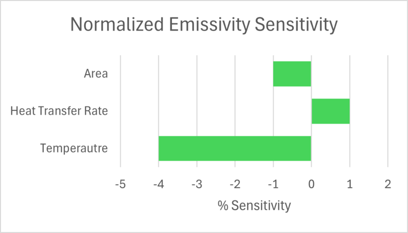
<html> <la-tex>\frac{\partial \epsilon_H}{\partial T_H} = \frac{-4*500W}{(1.0 m^2) * 5.67E-8 \frac{W}{m^2K^4}*(380 K)^5} = \frac{-0.004}{K} </la-tex> </html> | |||
Normalizing | |||
<html> <la-tex>(\frac{Q_H}{\epsilon_H})(\frac{\partial \epsilon_H}{\partial Q_H}) = (\frac{500W}{0.423})(\frac{8.458E-4}{W}) = 1.000 </la-tex> </html> | |||
<html> <la-tex>(\frac{A}{\epsilon_H})(\frac{\partial \epsilon_H}{\partial A}) = (\frac{1m^2}{0.423})(\frac{-0.423}{m^2}) = -1.000 </la-tex> </html> | |||
<html> <la-tex>(\frac{T_H}{\epsilon_H})(\frac{\partial \epsilon_H}{\partial T_H}) = (\frac{380K}{0.423})(\frac{-0.004}{K}) = -4.000 </la-tex> </html> | |||
[[File:VEMtordano1.png|center|800x600px]] | |||
<div style="text-align: center;"> | |||
Figure 10: Normalized Emissivity Sensitivity | |||
</div> | |||
So, for instance, Figure 10 suggests that a 1% increase in temperature produces a 4% decrease in emissivity. | |||
Moving onto the partial differentiation of Temperature Hysteresis | |||
<html> <la-tex> \DeltaT_{hys} = T_{up}^* - T_{down}^*</la-tex> </html> | |||
<html> <la-tex> \frac{\partial(\DeltaT_{hys})}{\partial T_{up}^*} = 1.000 [-]</la-tex> </html> | |||
<html> <la-tex> \frac{\partial(\DeltaT_{hys})}{\partial T_{down}^*} = -1.000 [-]</la-tex> </html> | |||
Normalizing, using information from the AFRL VO2 W(0%) VEM [1], yields | |||
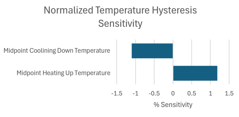
<html> <la-tex> \frac{T_{up}^*}{\DeltaT_{hys}} \frac{\partial(\DeltaT_{hys})}{\partial T_{up}^*} = \frac{353.15K}{298.15K}(1.000) = 1.184 </la-tex> </html> | |||
<html> <la-tex> \frac{T_{down}^*}{\DeltaT_{hys}} \frac{\partial(\DeltaT_{hys})}{\partial T_{down}^*} = \frac{328.15K}{298.15K}(-1.000) = -1.101 </la-tex> </html> | |||
[[File:VEMtornado22.png|center|800x600px]] | |||
<div style="text-align: center;"> | |||
Figure 11: Normalized Temperature Hysteresis Sensitivity | |||
</div> | |||
==8. Financial Model== | |||
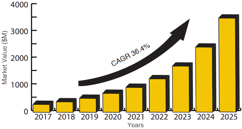
The metamaterial market is expected to grow, and it is projected to do so continuously; this includes vanadium-dioxide thin-film metamaterials. Figure 12 shows the global metamaterial market growth as predicted in 2018 [10]. | |||
[[File:metamaterialMarket.png|center|800x600px]] | |||
<div style="text-align: center;"> | |||
Figure 12: Metamaterial market, from [10] | |||
</div> | |||
There isn’t an exact cost in the available literature for the price of making and developing thin-film vanadium dioxide metamaterials, but the production cost is typically high because of the advanced manufacturing techniques of the materials (such as pulsed laser deposition and chemical vapor deposition). | |||
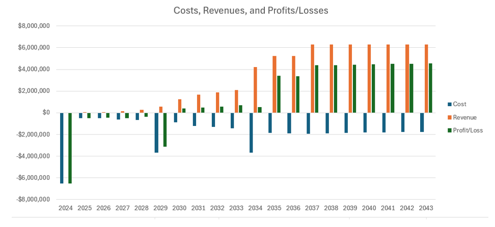
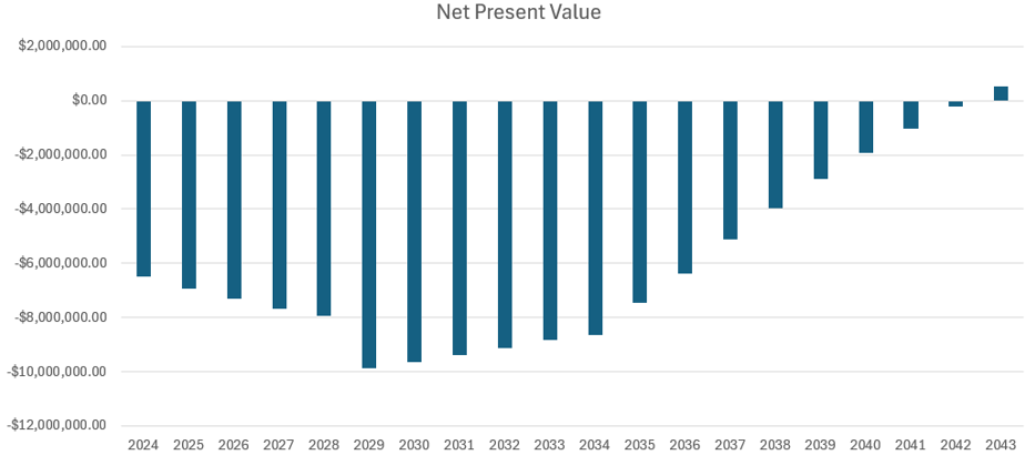
So, there will be an expensive initial investment, but there is expected to be a net profit in 2030 due to the growing market of metamaterials. | |||
For calculating the total cost, the company expects to pay $6 million dollars initially in 2024 for facility construction, and the company plans to expand the facility in 2029 for an estimated cost of $3 million dollars so that it would be possible to manufacture and test more radiators. There is another planned expansion of the facility in 2034 to further expand manufacturing and testing facilities, which is estimated to cost $2 million dollars. It is assumed that the average manufacturing cost of the radiator is $500 and that the manufacturing cost decreases 10% per year due to advancements in metamaterial technology. There are also recurring costs associated with facility management and employee payroll that typically increase. | |||
The company plans to ramp up to produce 3,000 radiators per year in 2037. This is expected because the VEM technology is expected to be common, and the number of satellites launched into space continues to increase as launch service costs decrease; there were over 2000 satellites launched into space in 2022 [11]. | |||
The company plans to spend 5% of its revenue on R&D every year, and this should make it possible to meet the company’s FOM goals. Figure 13 shows the company’s projected costs, revenues, and profits/losses from the year 2024 to 2043. | |||
[[File:VEMsCRPLtry2.png|center]] | |||
<div style="text-align: center;"> | |||
Figure 13: Projected costs, revenues, and profits/losses | |||
</div> | |||
Figure 14 shows the projected net present value of the company from the year 2024 to 2043. A discount rate of 10% was used to calculate the net present value. | |||
[[File:VEMsNPV.png|center]] | |||
<div style="text-align: center;"> | |||
Figure 14: Projected net present value | |||
</div> | |||
==9. Portfolio of R&D Projects and Prototypes== | |||
In enabling the successful use of passive VEMs in spacecraft thermal control, the company has identified several key project areas, including simulation, thermal testing, and demonstration of the technology on-orbit. The efforts in the table below highlight the progress made on these fronts by other companies, for which we intend to conduct in similar manners. | |||
{| class="wikitable" | |||
|- | |||
! Project Type !! Project Name !! Company !! Description | |||
|- | |||
| R&D|| Evaluating Variable-Emissivity Surfaces for Radiative Thermal Control [2] || Northrop Grumman || In this project, Northrop Grumman simulated the theoretical performance of VEM designs under different thermal loads, performance targets, and thermal masses. They concluded that a critical step forward is to design VEMs for total hemispherical emissivity of the full thermal spectrum for a given operating temperature. | |||
|- | |||
| R&D || VO2-based Thin-Film Smart Radiator Device for improved Passive Thermal Control of Space Systems [5]|| MPB Communications || MPB Communications fabricated 4-6 cm x 4-6 cm VEM tiles doped with VO2, specifically for passive spacecraft thermal control. They validated the technology for 1100 cycles between -60 deg. C and +80 deg. C and performed thermal shock tests. | |||
|- | |||
| R&D || Thermal Control Tiles as Smart Technologies for Harsh Space Environments [4] || University of Manitoba || The University of Manitoba further tested the VEMs designed by MPB communications in thermal vacuum chambers. They studied the radiative heat transfer of the materials on mock CubeSat panels as they used switched emissive states at 25 deg. C. It should be noted that the specific VEMs tested are currently onboard Kepler Communications satellites. | |||
|- | |||
| Demonstrator || Space Power InfraRed Regulation and Analysis of a Lifetime (SPIRRAL) [6][12] || AFRL || The SPIRRAL experiment, which launched on November 4, 2024, hosts several samples of VEMs outside the International Space Station. The VEM use case in this project is aimed at thermal control for space solar power beaming systems. | |||
|- | |||
|} | |||
==10. Key Publications and Patents== | |||
Below are descriptions of key publications and patents related to thermochromic radiators used for spacecraft. | |||
=== Publications === | |||
There have been several papers related to thermochromic spacecraft radiators. Below is a list of two important papers. | |||
*'''Title:''' VO2-based smart coatings with improved emittance-switching properties for an energy-efficient near room-temperature thermal control of spacecrafts | |||
**'''Authors:''' A. Hendaoui, N. Émond, S. Dorval, M. Chaker, and E. Haddad | |||
**'''Year:''' 2013 | |||
**'''Journal:''' Solar Energy Materials and Solar Cells, volume 117, pages 494-498 | |||
**'''DOI:''' https://doi.org/10.1016/j.solmat.2013.07.023 | |||
**'''Summary of Paper:''' Vanadium dioxide thin-film radiators were improved for spacecraft thermal control by adding a silicon-oxide layer and by doping with tungsten, which increased the material’s tunability (<html><la-tex>\Delta\varepsilon</la-tex></html>), increased the maximum emissivity (<html><la-tex>\varepsilon_H</la-tex></html>), lowered the transition temperature of the material, and decreased hysteresis. | |||
**'''Relevance of Paper:''' This paper improved several Figures of Merit of thermochromic vanadium dioxide radiators. | |||
*'''Title:''' VO2-based switchable radiator for spacecraft thermal control | |||
**'''Authors:''' Heungsoo Kim, Kwok Cheung, Raymond C. Y. Auyeung, Donald E. Wilson, Kristin M. Charipar, Alberto Piqué, and Nicholas A. Charipar | |||
**'''Year:''' 2019 | |||
**'''Journal:''' Nature Scientific Reports, 9, article number 11329 | |||
**'''DOI:''' https://doi.org/10.1038/s41598-019-47572-z | |||
**'''Summary of Paper:''' Calorimetric and optical measurements of vanadium dioxide thin film materials were taken to characterize their use case in spacecraft. Theoretical and experimental radiative properties are presented. | |||
**'''Relevance of Paper:''' Unlike many papers that were published before, this paper provided calorimetric measurements of vanadium dioxide thin film materials. Calorimetric measurements are more suited for calculating total radiative heat transfer than optical measurements. | |||
=== Patents === | |||
Because metamaterial thermochromic radiators is not a technology that has been widely used in spacecraft, there are relatively few patents related to it being used on spacecraft. However, there are decades worth of patents describing how to prepare thin film coatings, electrochromic radiators, and similar areas that are related to thermochromic spacecraft radiators. Below is a list describing two important US patents related to thermochromic radiators for spacecraft. | |||
* '''Title:''' THERMAL CONTROL COATINGS | |||
**'''Patent Number:''' US 7.691,435 B2 | |||
**'''Date of Patent:''' Apr. 6, 2010 | |||
**'''Inventors:''' John G. Keller, Robert M. Moy, Jane R. Felland | |||
**'''Assignee:''' The Boeing Company | |||
**'''Classifications:''' C23C28/042, C23C28/322, C23C28/34, C23C28/3455, C23C28/42 | |||
**'''Description of Invention:''' A multi-layer thermal control coating for spacecraft that may have thermochromic layers of silicon and vanadium dioxide in addition to having solar rejection layers made from zinc sulfide and magnesium fluoride. | |||
**'''Relevance of Invention:''' It describes another way of incorporating vanadium dioxide thermochromic material into spacecraft radiators. | |||
* '''Title:''' VARIABLE EMITTANCE THERMOCHROMIC MATERIAL AND SATELLITE SYSTEM | |||
**'''Patent Number:''' US 7,761,053 B2 | |||
**'''Date of Patent:''' Jul. 20, 2010 | |||
**'''Inventors:''' Roman V. Kruzelecky, Emile Haddad, Brian Wong, Wes R. Jamroz | |||
**'''Assignee:''' MPB Communications Inc. | |||
**'''Classifications:''' C09K9/00, Y10T428/24413, Y10T428/2462, Y10T428/24851, Y10T428/24893, Y10T428/24909, Y10T428/31504, Y10T428/31678 | |||
**'''Description of Invention:''' Multiple variations of a thermochromic variable emissivity material used for spacecraft radiators, some of which have vanadium dioxide as the transition metal. These materials are used for communications satellites. | |||
**'''Relevance of Invention:''' MBP Communications Inc. flew their thermochromic smart radiator device on a Canadian small satellite in the 2020's [4][5]. | |||
==11. Technology Strategy Statement== | |||
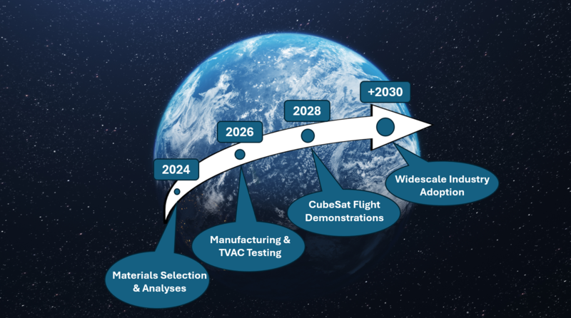
Our company strives to develop a VEM that can outperform existing VEMs under consideration for passive spacecraft thermal control in terms of emissive range and temperature hysteresis. Our goal is to develop a VEM with a hot-state emissivity of 0.9, cold state emissivity of 0.075 (delta emissivity = 0.825), and temperature hysteresis of 2.5 K. Initial efforts will focus on materials selection and thermal analysis modeling. Then, we will manufacture our technology and put it under thermal cycle testing in a thermal vacuum chamber. By 2028, we aim to perform space flight demonstrations and verifications of our technology on several university CubeSats in various orbits. Our final goal in the 2030s is to manufacture our product on a larger scale and market our VEM to professional aerospace companies such that they are being used for commercial spacecraft. These goals are also summarized in the swoosh chart below. | |||
[[File:VEMSwoosh.png|center|800x600px]] | |||
<div style="text-align: center;"> | |||
Figure 15 VEM Swoosh Chart | |||
</div> | |||
==Sources== | ==Sources== | ||
[1] | [1] https://arc-aiaa-org.libproxy.mit.edu/doi/abs/10.2514/6.2024-1295 | ||
[2] https://arc.aiaa.org/doi/10.2514/1.T6555 | |||
[3] https://doi.org/10.1016/j.xcrp.2022.101198 | |||
[4] https://umstarlab.ca/index.php/past-projects/ | |||
[5] https://ttu-ir.tdl.org/items/4b815052-4a4a-4031-9624-48605cae9c89 | |||
[6] https://afresearchlab.com/technology/space-power-beaming/ | |||
[7] https://ntrs.nasa.gov/citations/20220018746 | |||
[8] https://www.nasa.gov/wp-content/uploads/2024/07/civil-space-shortfall-ranking-july-2024.pdf?emrc=67223caeba458 | |||
[9] https://hal.science/hal-03327635v1 | |||
[10] https://deepblue.lib.umich.edu/handle/2027.42/145155 | |||
[11] https://www.nasa.gov/smallsat-institute/sst-soa/integration-launch-and-deployment/ | |||
[12] https://www.afrl.af.mil/News/Article-Display/Article/3977263/revolutionizing-space-based-thermal-systems-afrls-spirral-launch-on-spx-31/ | |||
Latest revision as of 00:24, 5 December 2024
Technology Roadmap Sections and Deliverables
- 4VEM - Variable Emissivity Materials for Spacecraft
Passive, thermochromic variable emissivity materials (VEMs) can be used for a wide range of applications, from spacecraft radiators to windows used on Earth. For this technology roadmap, the use of VEMs for spacecraft radiators will be the focus.
1. Roadmap Overview
The only way that orbiting spacecraft can reject heat is through radiation. Because of this, the thermo-optical properties of spacecraft radiators are important. The thermo-optical properties of radiators, such as emissivity, determine how much heat is radiated away.
There is a way to calculate how much heat is radiated from a surface, and it is shown in the equation below. Q is heat being radiated away from a surface, A is the area of the radiating surface, σ is the Stefan-Boltzmann constant, ε is the emissivity of the surface material, and T is the temperature of the surface.
The emissivity of a material is directly proportional to the heat radiated away. So, when a material has high emissivity, more heat is radiated away. Most materials have a constant emissivity, but there are some materials whose emissivity can change based on environmental conditions or whether they are powered. These materials are called variable emissivity materials (VEMs).
There are active (electrochromic) and passive (thermochromic) VEMs. Electrochromic VEMs require power input to change emissivity, unlike thermochromic VEMs which change their emissivity based on their temperature. The technology of thermochromic VEMs whose emissivity is lower at low temperatures and higher at high temperatures is expected to be widely used in radiators for spacecraft, because compared to constant-emissivity radiators, it reduces spacecraft heater power requirements and temperature swings, all without power or human input. Figure 1 shows how a thermochromic VEM can help spacecraft more efficiently manage their temperature.
Figure 1: Diagram of how VEMs affect spacecraft, from [1]
This roadmap will explore how passive, thermochromic VEMs have evolved, their Figures of Merit, what is expected in the future, and the company's plans to develop VEM technology.
2. Design Structure Matrix (DSM) Allocation
Figure 2 below shows the interactions between various technologies and the 4VEM variable emissivity technology. The x's in the matrix signify interaction.
Figure 2: DSM Matrix
VEMs are part of a larger technology tree. Figure 3 below shows the technology tree.
Figure 3: 4VEM Technology Tree Placement
In the tree, the 1st level is the technology of a general spacecraft:
- 1SPC Spacecraft
The 1SPC Spacecraft technology has a variety of subsystem technologies; all of the subsystems of a spacecraft interact with each other and make the spacecraft work, and they make up the second level:
- 2STR Structures Subsystem
- 2POW Power Subsystem
- 2CDH Command and Data Handling Subsystem
- 2ADC Attitude Determination and Control Subsystem
- 2PAY Payload Subsystem
- 2PRO Propulsion Subsystem
- 2COM Communication Subsystem
- 2THE Thermal Subsystem.
VEMs are part of the 2THE thermal subsystem of a spacecraft. Many technologies are used for spacecraft thermal subsystems, and they are in the 3rd level:
- 3HEP Heat Pipes
- 3LOU Louvers
- 3HEA Heaters
- 3CRY Cryocoolers
- 3PCM Phase-change materials
- 3TIM Thermal interface materials
- 3RAD Radiators
VEMs are used in the 3RAD Radiators technology. The 3RAD technology can be split into two groups as well, which comprise the 4th level:
- 4CEM Constant emissivity materials used for radiators
- 4VEM Variable emissivity materials used for radiators.
So, VEMs are a small part of the whole spacecraft technology.
3. Roadmap Model using OPM
The Object-Process Diagram (OPD) and Object-Process Language (OPL) represented in Figure 4 and Figure 5, respectively, were generated by OPCloud. This model describes the processes and Figures of Merit (FOM) involved with passive spacecraft VEMs, as well as their object interactions. It highlights the thermochromic VEMs discussed in this roadmap, which require no electrical energy to operate.
Figure 4: VEM OPD
Figure 5: VEM OPL
4. Figures of Merit (FOM)
There are several Figures of Merit (FOMs) that describe VEMs. In order to describe the FOMs, an emissivity vs. temperature graph of several VEMs made from vanadium dioxide doped with tungsten will be shown in Figure 6, which is from [1].
Figure 6: Emissivity versus Temperature for Some VEMs, from [1]
There are four types of VEMs shown in Figure 6; each VEM is made from vanadium dioxide doped with different percentages of tungsten. The first VEM is doped with 3.5% tungsten (the MPB W(3.5%) VEM), the second VEM is doped with 2.5% tungsten, the third VEM is doped with 1.5% tungsten, and the last VEM is doped with 0% tungsten.
For each type of VEM, there is an up curve and a down curve. The up curve corresponds to the emissivity profile when the material is being heated up, and the down curve corresponds to the emissivity profile when the material is being cooled down. The logistic fit curve fits the data to a logistic equation, and the midpoint line is in between the up and down curves.
Because there is a difference in the emissivity vs. temperature curves for when the material is being heated up and when the material is being cooled down, there is hysteresis. One FOM of VEMs is seeing how much hysteresis there is in the material. The less hysteresis, the better because it is easier and quicker to model VEMs with no hysteresis.
One way to calculate the amount of hysteresis is to determine at what temperature the material is when emissivity is at its midpoint and compare that temperature between the heating curve and the cooling curve. So, for the MPB W(0%) down curve, the midpoint temperature
For the MPB W(0%) curve,
The lower
There is also the minimum emissivity
So, two FOMs are the minimum emissivity
Another FOM engineers and scientists have been using in analyzing VEM technology is the difference between the minimum emissivity
So, for the MPB W(0%) midpoint curve, with an
The closer
The table below presents the FOM that can be used to evaluate various VEMs, with the most important ones being the emissivity values and temperature hysteresis.
| Figure of Merit | Units | Description |
|---|---|---|
| Temperature Hysteresis ( |
[K] | This describes how large hysteresis is for the VEM, and it is a difference of temperatures. The smaller the quantity, the better. The nominal value is 0 Kelvin (or 0 degrees Celsius). |
| Minimum Emissivity ( |
[-] | This is the minimum emissivity of a VEM. The nominal value is 0. |
| Maximum Emissivity ( |
[-] | This is the maximum emissivity of a VEM. The nominal value is 1. |
| Emissivity Range ( |
[-] | This is the difference between the maximum and minimum emissivities of VEMs. The nominal value is 1. |
| Lifetime ( |
[Cycles] | This is the number of emissivity state switches the material can undergo before failure. The higher this value, the better the VEM. |
| Response Time ( |
[s] | This is the amount of time it takes for the device to switch between different emissivity states. The lower the response time, the better the thermal control. |
Figure 7 displays a diverse spread of variability in emissivity ranges for active and passive types of modern VEMs over time using data from [2] and [3], which also include the specific VEM technologies plotted. The distribution of the emissivity ranges is a reminder that emissivity range may not necessarily be the most important figure of merit for a specific VEM application, hence why there is not a clear upward trend in the data over time. Although the data is very disperse, linear regression models were applied, and they show an improvement for electrochromic and thermochromic VEMs of 0.02/year and 0.03/year, respectively. Due to physics principles, the theoretical emissivity range for a given material is 1, with the maximum emissivity being 1 and the minimum being 0. This cannot exceed 1 due to the law of conservation of energy. That it, an object cannot emit more than 100% of its energy. In terms of application to passive spacecraft thermal control, thermochromic VEMs are at the incubation stage of the technology lifecycle because very few VEMs have been sent to space. One VEM technology, Thermal Control Tiles designed by MPB Communications, was sent to space in the early 2020's [4][5], and the Air Force Research Laboratory launched a VEM experiment to the International Space Station (ISS) on November 4, 2024, to study how VEMs behave in low Earth Orbit outside of the ISS for a year [12].
Figure 7: Modern VEM Emissivity Ranges with Data Adapted from [2] and [3]
5. Alignment with Company Strategic Drivers
Below is a table that has company strategic drivers, how they align with the roadmap, and targets for the company.
| Number | Strategic Driver | Alignment and Targets |
|---|---|---|
| 1 | To develop a commercially viable variable emissivity material that significantly reduces spacecraft heater power requirements and temperature swings and will generate profit for the company in the long term. | The 4VEM roadmap's goal is produce a variable emissivity material with an |
| 2 | To develop commercially viable dust-mitigated variable emissivity radiators for spacecraft on the moon. Lunar dust greatly affects spacecraft radiators on the moon [7], so by incorporating dust mitigation technology into the company's variable emissivity materials, the market can expand to lunar spacecraft more easily. | The target would be to develop a variable emissivity material that easily repels lunar dust. This driver is not currently aligned with the roadmap because the FOMs that are explored in this roadmap are not about how VEMs repel lunar dust. |
Strategic driver 1 and its targets are the main goal for the company's R&D department. The company will make investments to improve
One of NASA's main civil space technology shortfalls is surviving the lunar night [8], and having dust-mitigated VEMs will help spacecraft on the moon survive the night by decreasing heater power required. So, the company would like to eventually expand to create lunar dust-mitigated variable emissivity materials, but it will not be the main focus of the company currently; strategic driver 2 is not a requirement of this roadmap.
6. Positioning of Company versus Competition
Figures 8 and 9 display the current FOM capabilities of several VEMs for passive spacecraft thermal control, including ones created by the Air Force Research Lab (AFRL) [1] and Commissariat à l’energie Atomique (CEA) & Centre National d'études Spatiales (CNES) [9]. Also included are the utopia points, or theoretical limits, of these FOMs. An ideal VEM will have an emissivity range of 1, with its hot-state emissivity = 1 (for maximum radiative heat transfer), and its cold-state emissivity = 0 (for minimum radiative transfer). An ideal VEM also has a temperature hysteresis = 0, meaning its emissivity vs temperature curve is not dependent on whether the material is heating up or cooling down. The goal for our company by 2026 is to make improvements to the current state-of-the-art materials by creating a VEM capable of achieving a hot-state emissivity = 0.9, a cold-state emissivity = 0.075, and a temperature hysteresis = 2.5 K. This will be achieved by extensive analyses, material selection, simulation, testing, and experimentation.
Figure 8: Emissivity States of Several Passive VEMs for Spacecraft Thermal Control. Data adapted from [1] and [9].
Figure 9: Temperature Hysteresis of Several Passive VEMs for Spacecraft Thermal Control. Data adapted from [1] and [9].
7. Technical Model
The governing technical model for a passive VEM consists of a logistic growth function for emissivity as a function of temperature per [1].
Where
The below table presents a morphological matrix consisting of the relevant design characteristics of several VEMs under consideration for passive spacecraft thermal control by the Air Force Research Lab (AFRL) [1] and Commissariat à l’energie Atomique (CEA) & Centre National d'études Spatiales (CNES) [9].
| Company | AFRL | AFRL | CEA & CNES | CEA & CNES |
|---|---|---|---|---|
| Material | VO2 | VO2 | VO2 | VO2 w/ Solar Protection |
| Tungsten Doping % [W(%)] | 0.0 | 3.5 | Unkown | Unkown |
| Emissivity (hot) [-] | 0.8 | 0.81 | 0.5 | 0.75 |
| Emissivity (cold) [-] | 0.32 | 0.37 | 0.4 | 0.4 |
| Emissivity (range) [-] | 0.48 | 0.44 | 0.1 | 0.35 |
| Temperature Hysteresis [K] | 25.0 | 5.0 | 10.0 | 10.0 |
The most important FOMs for a VEM include the hot-state emissivity, cold-state emissivity, and temperature hysteresis. To find which parameters of variables these FOMs are most sensitive to, a sensitivity analysis can be conducted via the partial derivative method of the key FOM equations, which have been previously described. Beginning with emissivity
Using the nominal hot-case values in the table below, adapted from a theoretical VO2 VEM presented in [2], the partial derivative calculations can be normalized for a sensitivity analysis. Since the equation holds for hot and cold states of a given object, the emissivity sensitivity to different variables at the hot and cold states will be equal.
| Hot-Case | Cold-Case | |
|---|---|---|
| Heat Transfer Rate [W] | 500.0 | 50.0 |
| Radiative Area [m^2] | 1.0 (assumed) | 1.0 (assumed) |
| Emissivity [-] | 0.423 | 0.218 |
| Material Temperature [K] | 380 | 300 |
Proceeding with the hot-case values
Normalizing
Figure 10: Normalized Emissivity Sensitivity
So, for instance, Figure 10 suggests that a 1% increase in temperature produces a 4% decrease in emissivity.
Moving onto the partial differentiation of Temperature Hysteresis
Normalizing, using information from the AFRL VO2 W(0%) VEM [1], yields
Figure 11: Normalized Temperature Hysteresis Sensitivity
8. Financial Model
The metamaterial market is expected to grow, and it is projected to do so continuously; this includes vanadium-dioxide thin-film metamaterials. Figure 12 shows the global metamaterial market growth as predicted in 2018 [10].
Figure 12: Metamaterial market, from [10]
There isn’t an exact cost in the available literature for the price of making and developing thin-film vanadium dioxide metamaterials, but the production cost is typically high because of the advanced manufacturing techniques of the materials (such as pulsed laser deposition and chemical vapor deposition).
So, there will be an expensive initial investment, but there is expected to be a net profit in 2030 due to the growing market of metamaterials.
For calculating the total cost, the company expects to pay $6 million dollars initially in 2024 for facility construction, and the company plans to expand the facility in 2029 for an estimated cost of $3 million dollars so that it would be possible to manufacture and test more radiators. There is another planned expansion of the facility in 2034 to further expand manufacturing and testing facilities, which is estimated to cost $2 million dollars. It is assumed that the average manufacturing cost of the radiator is $500 and that the manufacturing cost decreases 10% per year due to advancements in metamaterial technology. There are also recurring costs associated with facility management and employee payroll that typically increase.
The company plans to ramp up to produce 3,000 radiators per year in 2037. This is expected because the VEM technology is expected to be common, and the number of satellites launched into space continues to increase as launch service costs decrease; there were over 2000 satellites launched into space in 2022 [11].
The company plans to spend 5% of its revenue on R&D every year, and this should make it possible to meet the company’s FOM goals. Figure 13 shows the company’s projected costs, revenues, and profits/losses from the year 2024 to 2043.
Figure 13: Projected costs, revenues, and profits/losses
Figure 14 shows the projected net present value of the company from the year 2024 to 2043. A discount rate of 10% was used to calculate the net present value.
Figure 14: Projected net present value
9. Portfolio of R&D Projects and Prototypes
In enabling the successful use of passive VEMs in spacecraft thermal control, the company has identified several key project areas, including simulation, thermal testing, and demonstration of the technology on-orbit. The efforts in the table below highlight the progress made on these fronts by other companies, for which we intend to conduct in similar manners.
| Project Type | Project Name | Company | Description |
|---|---|---|---|
| R&D | Evaluating Variable-Emissivity Surfaces for Radiative Thermal Control [2] | Northrop Grumman | In this project, Northrop Grumman simulated the theoretical performance of VEM designs under different thermal loads, performance targets, and thermal masses. They concluded that a critical step forward is to design VEMs for total hemispherical emissivity of the full thermal spectrum for a given operating temperature. |
| R&D | VO2-based Thin-Film Smart Radiator Device for improved Passive Thermal Control of Space Systems [5] | MPB Communications | MPB Communications fabricated 4-6 cm x 4-6 cm VEM tiles doped with VO2, specifically for passive spacecraft thermal control. They validated the technology for 1100 cycles between -60 deg. C and +80 deg. C and performed thermal shock tests. |
| R&D | Thermal Control Tiles as Smart Technologies for Harsh Space Environments [4] | University of Manitoba | The University of Manitoba further tested the VEMs designed by MPB communications in thermal vacuum chambers. They studied the radiative heat transfer of the materials on mock CubeSat panels as they used switched emissive states at 25 deg. C. It should be noted that the specific VEMs tested are currently onboard Kepler Communications satellites. |
| Demonstrator | Space Power InfraRed Regulation and Analysis of a Lifetime (SPIRRAL) [6][12] | AFRL | The SPIRRAL experiment, which launched on November 4, 2024, hosts several samples of VEMs outside the International Space Station. The VEM use case in this project is aimed at thermal control for space solar power beaming systems. |
10. Key Publications and Patents
Below are descriptions of key publications and patents related to thermochromic radiators used for spacecraft.
Publications
There have been several papers related to thermochromic spacecraft radiators. Below is a list of two important papers.
- Title: VO2-based smart coatings with improved emittance-switching properties for an energy-efficient near room-temperature thermal control of spacecrafts
- Authors: A. Hendaoui, N. Émond, S. Dorval, M. Chaker, and E. Haddad
- Year: 2013
- Journal: Solar Energy Materials and Solar Cells, volume 117, pages 494-498
- DOI: https://doi.org/10.1016/j.solmat.2013.07.023
- Summary of Paper: Vanadium dioxide thin-film radiators were improved for spacecraft thermal control by adding a silicon-oxide layer and by doping with tungsten, which increased the material’s tunability (
\Delta\varepsilon ), increased the maximum emissivity (\varepsilon_H ), lowered the transition temperature of the material, and decreased hysteresis. - Relevance of Paper: This paper improved several Figures of Merit of thermochromic vanadium dioxide radiators.
- Title: VO2-based switchable radiator for spacecraft thermal control
- Authors: Heungsoo Kim, Kwok Cheung, Raymond C. Y. Auyeung, Donald E. Wilson, Kristin M. Charipar, Alberto Piqué, and Nicholas A. Charipar
- Year: 2019
- Journal: Nature Scientific Reports, 9, article number 11329
- DOI: https://doi.org/10.1038/s41598-019-47572-z
- Summary of Paper: Calorimetric and optical measurements of vanadium dioxide thin film materials were taken to characterize their use case in spacecraft. Theoretical and experimental radiative properties are presented.
- Relevance of Paper: Unlike many papers that were published before, this paper provided calorimetric measurements of vanadium dioxide thin film materials. Calorimetric measurements are more suited for calculating total radiative heat transfer than optical measurements.
Patents
Because metamaterial thermochromic radiators is not a technology that has been widely used in spacecraft, there are relatively few patents related to it being used on spacecraft. However, there are decades worth of patents describing how to prepare thin film coatings, electrochromic radiators, and similar areas that are related to thermochromic spacecraft radiators. Below is a list describing two important US patents related to thermochromic radiators for spacecraft.
- Title: THERMAL CONTROL COATINGS
- Patent Number: US 7.691,435 B2
- Date of Patent: Apr. 6, 2010
- Inventors: John G. Keller, Robert M. Moy, Jane R. Felland
- Assignee: The Boeing Company
- Classifications: C23C28/042, C23C28/322, C23C28/34, C23C28/3455, C23C28/42
- Description of Invention: A multi-layer thermal control coating for spacecraft that may have thermochromic layers of silicon and vanadium dioxide in addition to having solar rejection layers made from zinc sulfide and magnesium fluoride.
- Relevance of Invention: It describes another way of incorporating vanadium dioxide thermochromic material into spacecraft radiators.
- Title: VARIABLE EMITTANCE THERMOCHROMIC MATERIAL AND SATELLITE SYSTEM
- Patent Number: US 7,761,053 B2
- Date of Patent: Jul. 20, 2010
- Inventors: Roman V. Kruzelecky, Emile Haddad, Brian Wong, Wes R. Jamroz
- Assignee: MPB Communications Inc.
- Classifications: C09K9/00, Y10T428/24413, Y10T428/2462, Y10T428/24851, Y10T428/24893, Y10T428/24909, Y10T428/31504, Y10T428/31678
- Description of Invention: Multiple variations of a thermochromic variable emissivity material used for spacecraft radiators, some of which have vanadium dioxide as the transition metal. These materials are used for communications satellites.
- Relevance of Invention: MBP Communications Inc. flew their thermochromic smart radiator device on a Canadian small satellite in the 2020's [4][5].
11. Technology Strategy Statement
Our company strives to develop a VEM that can outperform existing VEMs under consideration for passive spacecraft thermal control in terms of emissive range and temperature hysteresis. Our goal is to develop a VEM with a hot-state emissivity of 0.9, cold state emissivity of 0.075 (delta emissivity = 0.825), and temperature hysteresis of 2.5 K. Initial efforts will focus on materials selection and thermal analysis modeling. Then, we will manufacture our technology and put it under thermal cycle testing in a thermal vacuum chamber. By 2028, we aim to perform space flight demonstrations and verifications of our technology on several university CubeSats in various orbits. Our final goal in the 2030s is to manufacture our product on a larger scale and market our VEM to professional aerospace companies such that they are being used for commercial spacecraft. These goals are also summarized in the swoosh chart below.
Figure 15 VEM Swoosh Chart
Sources
[1] https://arc-aiaa-org.libproxy.mit.edu/doi/abs/10.2514/6.2024-1295
[2] https://arc.aiaa.org/doi/10.2514/1.T6555
[3] https://doi.org/10.1016/j.xcrp.2022.101198
[4] https://umstarlab.ca/index.php/past-projects/
[5] https://ttu-ir.tdl.org/items/4b815052-4a4a-4031-9624-48605cae9c89
[6] https://afresearchlab.com/technology/space-power-beaming/
[7] https://ntrs.nasa.gov/citations/20220018746
[9] https://hal.science/hal-03327635v1
[10] https://deepblue.lib.umich.edu/handle/2027.42/145155
[11] https://www.nasa.gov/smallsat-institute/sst-soa/integration-launch-and-deployment/

