Difference between revisions of "High-Speed Rail Safety"
Yuki Soeda (talk | contribs) |
Yuki Soeda (talk | contribs) |
||
| Line 61: | Line 61: | ||
[[File:morphological matrix.png|frameless|500px|Morphological Matrix ]] | [[File:morphological matrix.png|frameless|500px|Morphological Matrix ]] | ||
(Blue:Shinkansen, Red:TGV, Green:ICE, Orange:CRH, Purple:Acela) | (Blue:Shinkansen, Red:TGV, Green:ICE, Orange:CRH, Purple:Acela) | ||
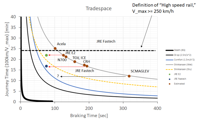
Figure below shows the tradespace between journey time and braking time. Note that the definition of “High Speed Rail” is that the maximum sustained speed of a train in service is over 250 km/hour, which is shown as the black dotted line. In addition to the frontiers of Shinkansen JRE2 in both wet (solid line) and dry (dashed line) conditions, the frontier in 8G deceleration (Death), one where passengers cannot keep their seats (Drop), and one in comfort situation (Comfort), that is, the passengers are able to hold on or remain seated as the train decelerates. Also, the estimated values of braking time and journey time of several high-speed trains, whose characteristics are shown in Table 4-3, are plotted under the condition that all the parameters except for mass and the maximum velocity are the same. For JRE E2 and JRE Fastech, the values written in [5] are also plotted as red circle and blue circle, respectively, to compare the actual values and the estimated values. | |||
Calculations reveal that, even when the weather is dry, the deceleration due to the adhesion friction is low enough that passengers can keep their seat with comfort. As the actual values of JRE E2 and JRE Fastech are closer to the “Comfort” curve, recent research has enabled more efficient braking to reduce the braking time. | |||
The SCMAGLEV is propelled by electromagnetic force, not by friction between the vehicle and the rail. This difference is indicated by unique behavior in the tradespace. The SCMAGLEV has potential to decelerate hard enough to drop passengers from their seats, which means SCMAGLEV theoretically can operate beyond the “Drop” curve. However, from the viewpoint of passengers’ safety, it cannot go beyond “Drop” curve unless restraints or other instruments are installed to keep the passengers in their seats during emergency braking. | |||
[[File:tradespace.png|frameless|800px|Trade Space ]] | |||
Revision as of 12:59, 5 November 2019
Roadmap Overview
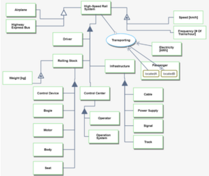
High-Speed Rail is a type of passenger rail transportation system that operates at high-speed with high voltage electricity. With respect for the multiple definitions for high-speed rail, the International Union of Railways defines high-speed rail as systems of rolling stock and infrastructure which regularly operate at or above 250 km/h on new tracks, or 200 km/h on existing tracks. Figure 8, above, shows the basic components of high-speed rail system. Rolling stock that obtain electricity from cable (as shown, or ground-based rail) as a power is operated by a driver who follows signals and communicates with one or more control centers. The dedicated or specifically upgraded tracks guide the train.
DSM Allocation
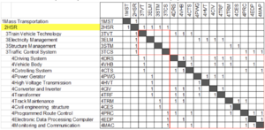
The DSM shows that the 2HSR is part of the mass transportation system in large context. It requires 3TVT Train Vehicle Technology, 3ELM Electricity Management, 3STM Structure Management, and 3TCS Traffic Control System. In addition, these level 3 technologies require level 4 technologies that are consist of 4 DRS Driving System of the vehicle such as motor, 4VHB Body of vehicles, 4CTS control system of the vehicle, 4PWG power generator or power plant of electricity, 4HVT technology for transmitting high voltage electricity, 4CIV converter and inverter inside the vehicle, 4TRF transforming electricity to appropriate voltage, 4TRM maintenance of tracks, 4CES maintenance of civil engineering structures such as bridges and tunnels, 4PRC route control system, 4EDP data processing unit, 4MAC technology for monitoring and communicating data.
Roadmap Model using OPM
The OPM describes the decomposition and primary function of HSR system. The level 1 decomposition of the system is Driver, Rolling Stock, Control Center and Infrastructure. Rolling Stock consists of physical components such as bogie and body. The main components of control center are Operator and Operation system that support drivers by providing information from several data sources and calculating the signal pattern. Infrastructure, such as tracks and signals, is the foundation of the system that physically and electrically support the operation.
Figures of Merit
| Figure of Merit | Units | Description |
|---|---|---|
| Maximum speed | km/hour | Maximum operational speed of trains |
| Frequency | # of trains/hour | Number of operated trains per hour |
| Weight | kg | Weight of train |
| Brake force | N | Force to stop the train |
| Brake stopping distance | m | Distance that it takes to come to a complete stop |
| Capacity | people/train | Number of passengers carried by train |
| Strength of Body | N/mm^2 | Strength against crash |
| CO2 emission | t/train/km | Amount of CO2 emitted by electricity generation used for operating one train |
| Construction cost | $/km | Initial cost for constructing total railway system per 1 km |
| Operation cost | $/train | Operational cost for a round-trip of a train |
Alignment with Company Strategic Drivers
Strategic Driver: To develop a safe, comfortable, and punctual high-speed train system that can stop as quickly as possible to minimize the possibility of collision and derailment.
Alignment and Targets: The HSR Technology Roadmap will target a dedicated track-guided system with powerful brake that can decelerate at 1.5m/s^2 and an obstacle sensor system that can detect and respond to any dangerous obstacle immediately. This driver is currently aligned with the HSR technology roadmap.
The continuous goal for the railway business is to develop a safe and convenient train system that is attractive to potential passengers. In the context of safety, the braking time should be as short as possible without injuring passengers due to a too intense jerk (jerk is the derivative of acceleration). The simplest way to reduce the braking time is to reduce speed. This approach is accepted by passengers when the train is traveling under bad conditions, such as heavy rain or mechanical troubles. Also, the total weight (vehicle weight + passengers’ weight) of the train would affect the braking time. In this context, reducing capacity would contribute to reduced braking time. However, operating at reduced profitability and efficiency, by reducing operational speed and capacity, would negatively affect the attractiveness of the system to passengers.
Positioning of Company vs. Competition
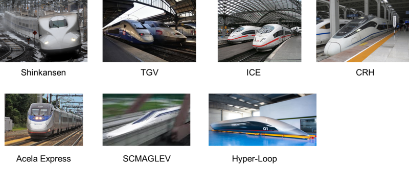
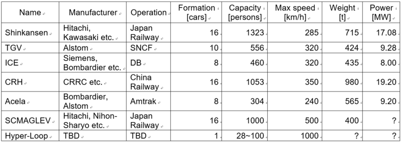
The figure below shows a summary of several types of high-speed rail systems, derived from public data. The Shinkansen in Japan has the largest capacity in the world and these trains are formally operated at a fixed number of cars. In Europe and China, the number of cars can change flexibly based on regions’ needs and the types of models. This flexibility better supports variabilities in demand but affects the operating cost and makes driving the vehicle more difficult. Typically, operational speed is capped by sharpness of curves and the strength of track components and infrastructure. China Railway has the highest operational speed supported by newer track and infrastructure and fewer sharp curves. However, unconventional systems such as maglev and hyper-loop, using totally different propulsion and guiding systems, enables trains to be operated at much higher speeds. The SCMaglev is now under construction in Japan and operating in test mode, while Hyper-loop systems are still in a concept phase and need further development to their core system. The table below also shows that the Acela Express is less efficient compared to other high-speed rail systems, with lower speed, less capacity, and heavier vehicles.
Technical Model
Table below shows the morphological matrix of the main technological decision variables on high-speed rail that would affect breaking system and safety. Five conventional railway systems (Blue:Shinkansen, Red:TGV, Green:ICE, Orange:CRH, Purple:Acela) are plotted on the matrix. Note that the architecture of the motor is different between TGV/Acela and others. These two trains are push-pull, with locomotives at both ends of the train, which has the advantage of flexibility in the number of cars between the locomotives and interoperability with local tracks. However, this configuration has a disadvantage with efficient braking because less motors acting on less axles are available to electrically deaccelerate the vehicle. The shape of the front affects air drag and noise when running at high speed. The Shinkansen is shaped carefully so that it can minimize noise that would adversely impact urban areas and going through tunnels. JR East is trying to develop air flaps that can increase air drag as part of emergency braking systems. To minimize weight, most rail systems use aluminum because it is light and easy to handle. Some companies are exploring the use of alloyed magnesium or carbon-fiber for the car body, but these technologies are not yet in production.
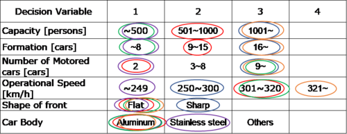 (Blue:Shinkansen, Red:TGV, Green:ICE, Orange:CRH, Purple:Acela)
Figure below shows the tradespace between journey time and braking time. Note that the definition of “High Speed Rail” is that the maximum sustained speed of a train in service is over 250 km/hour, which is shown as the black dotted line. In addition to the frontiers of Shinkansen JRE2 in both wet (solid line) and dry (dashed line) conditions, the frontier in 8G deceleration (Death), one where passengers cannot keep their seats (Drop), and one in comfort situation (Comfort), that is, the passengers are able to hold on or remain seated as the train decelerates. Also, the estimated values of braking time and journey time of several high-speed trains, whose characteristics are shown in Table 4-3, are plotted under the condition that all the parameters except for mass and the maximum velocity are the same. For JRE E2 and JRE Fastech, the values written in [5] are also plotted as red circle and blue circle, respectively, to compare the actual values and the estimated values.
Calculations reveal that, even when the weather is dry, the deceleration due to the adhesion friction is low enough that passengers can keep their seat with comfort. As the actual values of JRE E2 and JRE Fastech are closer to the “Comfort” curve, recent research has enabled more efficient braking to reduce the braking time.
The SCMAGLEV is propelled by electromagnetic force, not by friction between the vehicle and the rail. This difference is indicated by unique behavior in the tradespace. The SCMAGLEV has potential to decelerate hard enough to drop passengers from their seats, which means SCMAGLEV theoretically can operate beyond the “Drop” curve. However, from the viewpoint of passengers’ safety, it cannot go beyond “Drop” curve unless restraints or other instruments are installed to keep the passengers in their seats during emergency braking.
