Difference between revisions of "Solar-Powered HALE Aircraft, by Naoki Kobayashi, Alex Kunycky, Yuya Makino"
Yuya Makino (talk | contribs) |
Yuya Makino (talk | contribs) |
||
| Line 115: | Line 115: | ||
* '''Products''' | * '''Products''' | ||
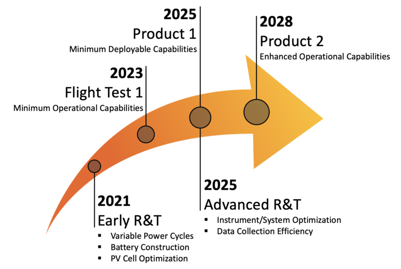
[[File: | [[File:HALEMAP2.png|600px]] | ||
* '''Long haul aircraft(Endurance time)''' | * '''Long haul aircraft(Endurance time)''' | ||
Revision as of 10:36, 3 December 2020
Roadmap Overview
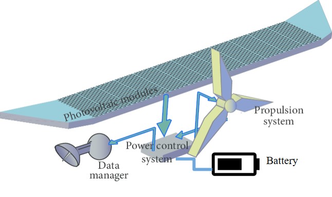
Solar powered High Altitude Long Endurance (HALE) aircraft are lightweight, high aspect ratio planes that generate electricity using photovoltaic cells on the lifting surfaces. It has been developed from 1990s, as a part of NASA projects named "The Environmental Research Aircraft and Sensor Technology(ERAST)". The first famous aircraft was Helios developed by AeroVironment. Recently, as battery and solar panel performance is developing, Airbus or another company are trying to develop. This aircraft will be deployed for month-long missions, as a closer alternative to satellite observation of the earth’s changing climate, so the aircraft must generate and store excess electricity during the day to stay aloft at night. The payload will include instrumentation only; the electrical “payload” required to run the instruments will be more critical than their relatively-low mass. The aircraft will enable climate scientists to make precise, prolonged measurements anywhere in the world, to inform and build climate models as the atmosphere continues to warm.
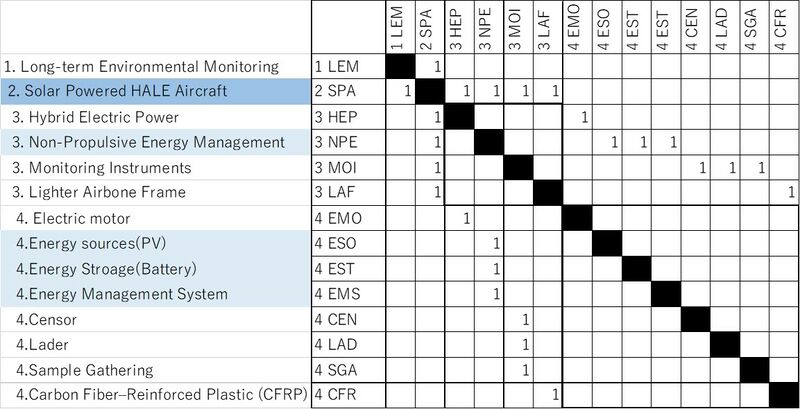
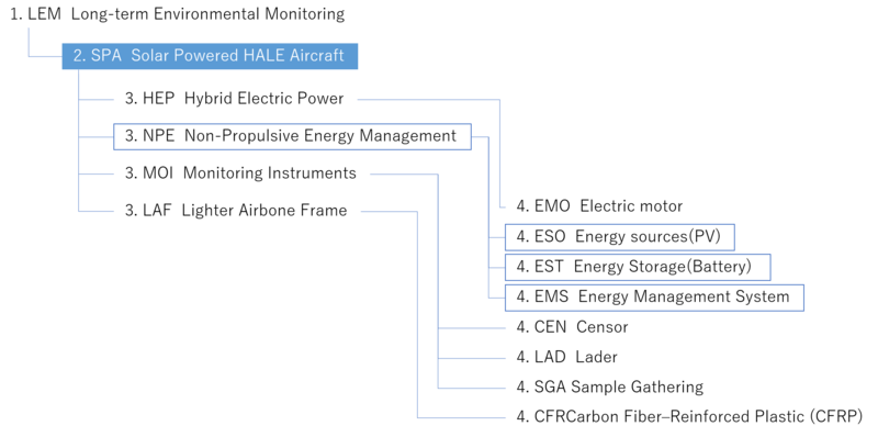
Design Structure Matrix (DSM) Allocation
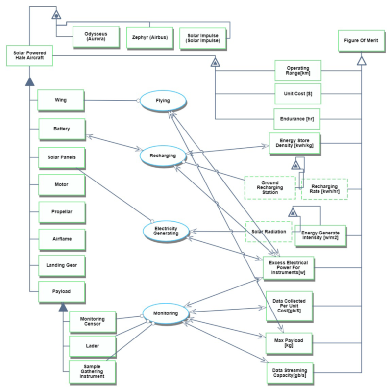
Roadmap Model using OPM
OPL:
Solar Powered Hale Aircraft is informatical and systemic.
Wing is physical and systemic.
Battery is physical and systemic.
Motor is physical and systemic.
Airflame is physical and systemic.
Solar Panels is physical and systemic.
Payload is physical and systemic.
Propellar is physical and systemic.
Landing Gear is physical and systemic.
Monitoring Censor is physical and systemic.
Lader is physical and systemic.
Sample Gathering Instrument is physical and systemic.
Solar Radiation of Energy Generate Intensity is physical and environmental.
Ground Recharging Station of Recharging Rate is physical and environmental.
Figure Of Merit is physical and systemic.
Energy Store Density is physical and systemic.
Energy Generate Intensity is physical and systemic.
Max Payload is physical and systemic.
Excess Electrical Power For Instruments is physical and systemic.
Recharging Rate is informatical and environmental.
Unit Cost of Solar Powered Hale Aircraft is physical and systemic.
Endurance of Solar Powered Hale Aircraft is physical and systemic.
Data Collected Per Unit Cost is physical and systemic.
Operating Range of Solar Powered Hale Aircraft is physical and systemic.
Data Streaming Capacity is physical and systemic.
Solar Powered Hale Aircraft consists of Airflame, Battery, Landing Gear, Motor, Payload,
Propellar, Solar Panels, and Wing.
Payload consists of Lader, Monitoring Censor, and Sample Gathering Instrument.
Data Collected Per Unit Cost, Data Streaming Capacity, Endurance, Energy Generate Intensity,
Energy Store Density, Excess Electrical Power For Instruments, Max Payload,
Operating Range, Recharging Rate, and Unit Cost are Figure Of Merit.
Energy Generate Intensity exhibits Solar Radiation.
Recharging Rate exhibits Ground Recharging Station.
Solar Powered Hale Aircraft exhibits Endurance, Operating Range, and Unit Cost.
Odysseus, Solar Impulse, and Zephyr are instances of Solar Powered Hale Aircraft.
Flying is physical and systemic.
Flying requires Wing.
Flying affects Excess Electrical Power For Instruments and Max Payload.
Recharging is physical and systemic.
Recharging requires Ground Recharging Station of Recharging Rate.
Recharging affects Battery, Energy Store Density, and Excess Electrical Power For Instruments.
Electricity Generating is physical and systemic.
Electricity Generating requires Solar Panels.
Electricity Generating affects Excess Electrical Power For Instruments.
Electricity Generating consumes Solar Radiation of Energy Generate Intensity.
Monitoring is physical and systemic.
Monitoring requires Lader, Monitoring Censor, and Sample Gathering Instrument.
Monitoring affects Data Collected Per Unit Cost, Data Streaming Capacity,
Excess Electrical Power For Instruments, and Max Payload.
Figures of Merit (FOMs)
The table below shows a list of key FOMs by which HALE can be assessed.
| FOM name | Units | Description |
|---|---|---|
| Endurance | km | Distance that can be traveled in an operation |
| Energy Density (Storage) | kWh/kg | Amount of energy that can be stored per unit volume |
| Power Density (Generation) | kW/M^2 | Amount of energy that can be generated per unit area |
| Amount of data | Mbps | Amount of data that can be collected by HALE |
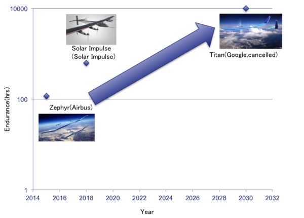
Endurance:
With the exception of ZEPHYR, no progress was made on range, as the main solar plane projects appear to be aimed at expanding payloads.
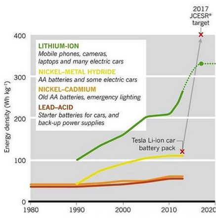
Energy Density (Storage):
From 1975 to 2014, its FOM changed from 45 to 240. So its annual rate of improvement is 4.4%.(45*1.044^39=241)
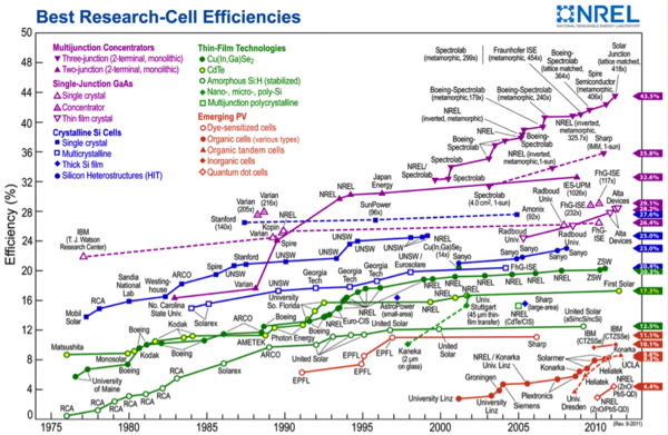
Power Density (Generation):
The conversion efficiency reached 46% in 2013, up from 1% in 1976; since 45% progress was made over 37 years, the average growth rate was 1.2%.
Amount of data:
We collected information on low-orbit satellites within 2,000 km altitude.
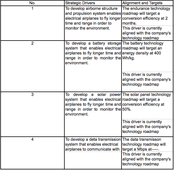
Alignment to Strategic Drivers
Table 4.1: Alignment to Strategic Drivers
Assume that the scanning width is 100 km compared to LEO. Then, since we move forward --km by 1 hour The amount of image data per unit of time when the data is captured by optics isーー. Assuming that the amount of data for the three types of data (vegetation data, sonic-based depth data) is about the same, the amount of data will be --Mbytes. Aerial photographs are taken in such a way that two-thirds of the image area is overlapped, allowing for stereoscopic viewing. Therefore, three times this amount of data transmission is required. As a result, ---Mbytes/s is needed.
Positioning of Company vs. Competition
- Products
- Long haul aircraft(Endurance time)
| Company | Endurance time | year |
|---|---|---|
| Aurora | For months | (have not fly) |
| Airbus | 25 days, 23 hour and 57 minute | 2018 |
| Solar Impulse | 117 hours, 52 minutes | 2015 |
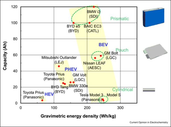
- Battely(Energy density)
[Recent progress in liquid electrolytes for lithium metal batteries, Current Opinion in Electrochemistry Volume 17, October 2019, Pages 106-113]
- Solar panel(conversion efficiency)
| Company | Conversion efficiency |
|---|---|
| SunPower | 22.3% |
| REC | 21.7% |
| LG | 21% |
| Panasonic | 20.3% |
| Solaria | 20% |
- Comparing HALE with LEO
Comparing HALE with low-orbit satellites. The current proven launch cost of SpaceX is currently $1 million per lightweight satellite. HALE, on the other hand, has no additional cost to launch. Therefore, HALE is considered to be more advantageous if launch cost is included.
Technical Model
The solar-powered HALE aircraft design is a combination of multiple technologies that require multiple design decisions within the design space. A morphographical matrix of some of those options is included below.
| Decision Variable | 1 | 2 | 3 | 4 |
|---|---|---|---|---|
| Wingspan [m] | 20 | 30 | 40 | 50 |
| Wing Area [m^2] | 20 | 40 | 60 | 80 |
| Battery Type | Li-ion | Ni-Hydride | Ni-Ca | Pd-Acid |
| Battery Capacity [kWh] | 50 | 100 | 150 | 200 |
| Propulsor Type | Propeller(s) | Ducted Fan(s) | ||
| Propulsor Power [kW] | 10 | 20 | 30 | 40 |
| Solar Cell Type | a-Si | c-Si | CI(G)S | CdTe |
| Solar Cell Capacity [kW] | 15 | 30 | 45 | 60 |
-v-v-v-v-v-v-v-v-v-v-v-v-v-v-v-v-v-v-v-v-v-v-v-v-v-v-v-v-v-v-v-v-v-
NOTE: Add data collection and streaming parameters.
-^-^-^-^-^-^-^-^-^-^-^-^-^-^-^-^-^-^-^-^-^-^-^-^-^-^-^-^-^-^-^-^-^-
-v-v-v-v-v-v-v-v-v-v-v-v-v-v-v-v-
Range and Endurance
Some of these options factor into assessments of the figures of merit. The first FOM to consider is endurance [hours] , which is closely related to range [km] . The Breguet range equation commonly describes maximum aircraft range. Rederiving the relation for battery electric aircraft yields
<math>R= \left(\frac{L}{D}\right) \eta_{total} \frac{e^{*}}{g} \frac{m_{batt}}{m_{total}} </math>
where <math> \eta_{total} </math> is the overall powertrain efficiency, <math> \left(\frac{L}{D}\right) </math> is the lift-to-drag ratio, and <math> e* </math> is the battery specific energy (kWh/kg). If we assume that the aircraft will (theoretically) fly just above stall speed for maximum endurance, we can define the cruise and loiter speed as the speed where lift is exactly equal to weight,
<math> v_{stall} = \sqrt{\frac{2m_{total}g}{C_LS\rho}} </math>
Endurance [hours] is then derived from range and speed to be
<math> t_{max} = \left(\frac{L}{D}\right) \eta_{total} \frac{e^{*}}{g} \frac{m_{batt}}{\left(m_{total}g\right)^{\frac{3}{2}}} \sqrt{\frac{C_LS\rho}{2}} </math>
where <math> C_L </math> is the coefficient of lift, <math> S </math> is the area of the lifting surfaces (generally, the wings), and <math> \rho </math> is the air density (generally, a function of altitude).
Partials are calculated to assess the relative impact of various aircraft parameters on the endurance.
-v-v-v-v-v-v-v-v-v-v-v-v-v-v-v-v-v-v-v-v-v-v-v-v-v-v-v-v-v-v-v-v-v-
Figure tornado chart of endurance parameters goes here.
-^-^-^-^-^-^-^-^-^-^-^-^-^-^-^-^-^-^-^-^-^-^-^-^-^-^-^-^-^-^-^-^-^-
The effect of aerodynamic parameters (<math>\frac{L}{D}</math>, <math>C_L</math>, <math>C_D</math>, <math>S</math>, and <math>\rho</math>) on range are given by
<math>\frac{\partial t_{max}}{\partial \left(\frac{L}{D}\right)}=\eta_{total} e^{*} \frac{m_{batt}}{\left(m_{total}g\right)^{\frac{3}{2}}} \sqrt{\frac{C_LS\rho}{2}}\\
\\
\frac{\partial t_{max}}{\partial C_L}= \frac{3}{2} \left(\frac{1}{C_D}\right) \eta_{total} e^{*} \frac{m_{batt}}{\left(m_{total}g\right)^{\frac{3}{2}}} \sqrt{\frac{C_LS\rho}{2}}\\
\\
\frac{\partial t_{max}}{\partial C_D}= -\left(\frac{C_L^{3/2}}{C_D^2}\right) \eta_{total} e^{*} \frac{m_{batt}}{\left(m_{total}g\right)^{\frac{3}{2}}} \sqrt{\frac{S\rho}{2}}\\
\\
\frac{\partial t_{max}}{\partial S}= \frac{1}{2} \left(\frac{L}{D}\right) \eta_{total} e^{*} \frac{m_{batt}}{\left(m_{total}g\right)^{\frac{3}{2}}} \sqrt{\frac{C_L\rho}{2S}}
\\
\frac{\partial t_{max}}{\partial \rho}= \frac{1}{2} \left(\frac{L}{D}\right) \eta_{total} e^{*} \frac{m_{batt}}{\left(m_{total}g\right)^{\frac{3}{2}}} \sqrt{\frac{C_LS}{2\rho}}</math>
The effect of battery parameters (<math>e^{*}</math> and <math>m_{batt}</math>) are given by
<math>\frac{\partial t_{max}}{\partial e^{*}}=\left(\frac{L}{D}\right) \eta_{total} \frac{m_{batt}}{\left(m_{total}g\right)^{\frac{3}{2}}} \sqrt{\frac{C_LS\rho}{2}} \\
\\
\frac{\partial t_{max}}{\partial m_{batt}}= \left(\frac{L}{D}\right) \eta_{total} e^{*} \left( \frac{1}{\left(m_{total}g\right)^{\frac{3}{2}}}-\frac{3m_{batt}}{2\left(m_{total}\right)^{\frac{5}{2}}} \right) \sqrt{\frac{C_LS\rho}{2}} </math>
The effects of powertrain efficiency are further investigated in the next section.
Powertrain Efficiency
The aircraft system is comprised of multiple subsystems, each with their own inherent efficiencies and sources of loss. During the day, the aircraft must generate and use power, as well as charge the batteries. At night, the aircraft must discharge those batteries to power the props. Normalizing the subsystem efficiencies to assess their influence, the impact of a 1% change in each factor is included in the tornado chart below. The chart highlights the outsized impact of improvements in solar cell efficiency as compared to the other factors. It also illustrates that the other electrical losses (e.g. motor efficiency) have generally less impact than the mechanical/aerodynamic losses (e.g. propeller efficiency). This suggests emphasis should be placed on both PV efficiency and aerodynamic aircraft design, with less investment on improving internal electronics.
The efficiency in flight for the aircraft to stay airborne is comprised of many subsystem efficiencies, represented for daytime and nighttime flight as
<math> \eta_{flight, day} = \left(\eta_{prop}\right) \left(\eta_{motor}\right) \left(\eta_{transfer}\right) \left(\eta_{generation}\right) \\ \\ \eta_{flight, night} = \left(\eta_{prop}\right) \left(\eta_{motor}\right) \left(\eta_{transfer}\right) \left(\eta_{discharge}\right) </math>
For each of these high-level efficiency calculations, the partials are straightforward and all follow the same general form of
<math> \frac{\partial \eta _{flight}}{\partial \eta _1} = \eta_2 \eta_3 \eta_4 </math>
Recharging and Power Density
One of the primary challenges for HALE UAVs is producing enough electricity to power the motors and keep the UAV airborne. Terrestrial PV solar arrays are installed at an optimal inclination from the horizon based on latitude, and sometimes with one- or two-axis solar tracking. A HALE aircraft, on the other hand, is constrained to net-level flight and the lower PV cell efficiencies that result.
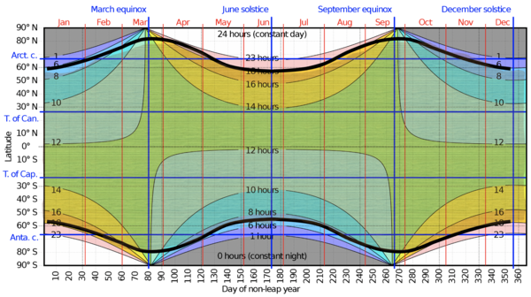
As a result, the final HALE UAV can operate in most, but not all, locations around the world throughout the year. However, a particular challenge of this HALE UAV is that one of its main applications is the monitoring of climate change phenomena, which will often involve loitering in polar regions (within the Arctic and Antarctic circles). These regions experience months-long days and nights during summers and winters, but also involve a particularly low angle of incidence, leading to much lower photovoltaic efficiency than is typically considered for solar installations.
NOTE: need to finish adding lines for each prototype and the final product.
The instantaneously-available power from sunlight is given by
[formula]
with solar irradiance, incidence angle, and PV efficiency.
[rest of formulas here...]
Data Collection
-v-v-v-v-v-v-v-v-v-v-v-v-v-v-v-v-v-v-v-v-v-v-v-v-v-v-v-v-v-v-v-v-v-
Section on instrument data collection and cost
-^-^-^-^-^-^-^-^-^-^-^-^-^-^-^-^-^-^-^-^-^-^-^-^-^-^-^-^-^-^-^-^-^-
Keys Publications and Patents
A non-aqueous electrolyte battery based on electrochemical intercalation with a carbon material as the anode and a lithium ion containing metal oxide as the cathode. This is the general definition of a lithium-ion battery.
A lithium-ion battery is a "secondary battery" that can be repeatedly charged and discharged and uses a "non-aqueous electrolyte". Prior to the advent of lithium batteries, batteries were based on aqueous solutions such as lead batteries. The lithium-ion battery was made smaller and lighter by the proposal to use an organic solvent instead of water for electrolysis. The first person to propose it was a man named Dr. Harris, who proposed it in his dissertation in 1956.
The next part is the "based on electrochemical intercalation" part. It is often said that the principle of a lithium-ion battery is moving of lithium ions. This phenomenon is also expressed in terms of electrochemical intercalation, which is a very important elemental technology. Professor Stanley Whittingham was the first to propose the application of this phenomenon to batteries in 1975.
The next part of the proposal was to "use lithium ion containing metal oxides as the cathode". Metal oxides that do not contain lithium ions cannot be used in lithium-ion batteries. In 1980, five years after Professor Whittingham's proposal, the world's first discovery of a cathode material containing lithium ions was made[1]. It was discovered by Dr. John Goodenough.
Dr. Whittingham proposed electrochemical intercalation, and Dr. Goodenough discovered the cathode material. Finally, Dr. Yoshino discovered carbon materials for the anode material, which led to the completion of the prototype of the lithium-ion battery in 1985 (In the United States, it was granted as a patent in 1987.)[2].
We have searched for patents and paper from these four important discoveries.
- [1] K. Mizushima, J.B. Goodenough et al., Materials Research Bulletin, 1980, 15, 783
- [2] Secondary Battery USP 4,668,595, 1987, Akira Yoshino, Kenichi Sanechika, Takayuki Nakajima.
- [3] J.B. Goodenough et al., EP17400B1, application date (priority) April 5, 1979
- [4] R. Yazami et al., International Meeting on Lithium Batteries, Rome, April 27–29, 1982, C.L.U.P. Ed. Milan, Abstract #23
An important paper on all-solid-state lithium batteries should also be included.
- [5] Braga, M. H., N. S. Grundish, A. J. Murchison, and J. B. Goodenough. 2017. “Alternative Strategy for a Safe Rechargeable Battery.” Energy and Environmental Science 10 (1): 331–36.
To aid in the technical model development, this paper describes various aircraft performance assessment metrics.
- [6] Benjamin J. Brelje and Joaquim R.R.A. Martins. Electric, hybrid, and turboelectric fixed-wing aircraft: A review of concepts, models, and design approaches. Progress in Aerospace Sciences, 2018.
Financial Model
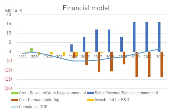
To build the financial model, we assume:
- We will sell our product from 2025(1st gen) and 2028(2nd gen)
- By then, we will have 4 R&D project(See the details in R&D Portfolio) and 3 test aircraft test flight(in 2023, 2024 and 2027).
- We sell product α for $400,000 with 10% margin and β for $400,000 for 15% margin. The rest of 90% or 85% is cost for manufacturing or other expense.
- We will get grant by the Japanese government(R&D subsidiary for Battely) $200000 in 2022s. projects within the railway company.
The table also includes the discount rate, assumed as 5%, and Net Present Value (NPV) for this research. The model shows that the R&D expenditures for first 7 years makes NPV negative, but after starting to sell product aircraft, it get positive in 2032.
[Table: Financial model]
[Table: R&D cost model]
[Table: Revenue model]
R&D Portfolio
The primary technology improvements to achieve this goal revolve around power generation, power storage, and overall power management for the HALE UAV. These related themes require investments in complementary, but independent, technologies that will eventually integrate into a successful HALE UAV system.
Power Generation
Perhaps the most important function for the HALE UAV is to generate a surplus of solar power, such that the aircraft can not only fly on station, but create and store enough power to continue flying through the night. Differences in solar incidence due to latitude and season further complicate this challenge, and require additional study.
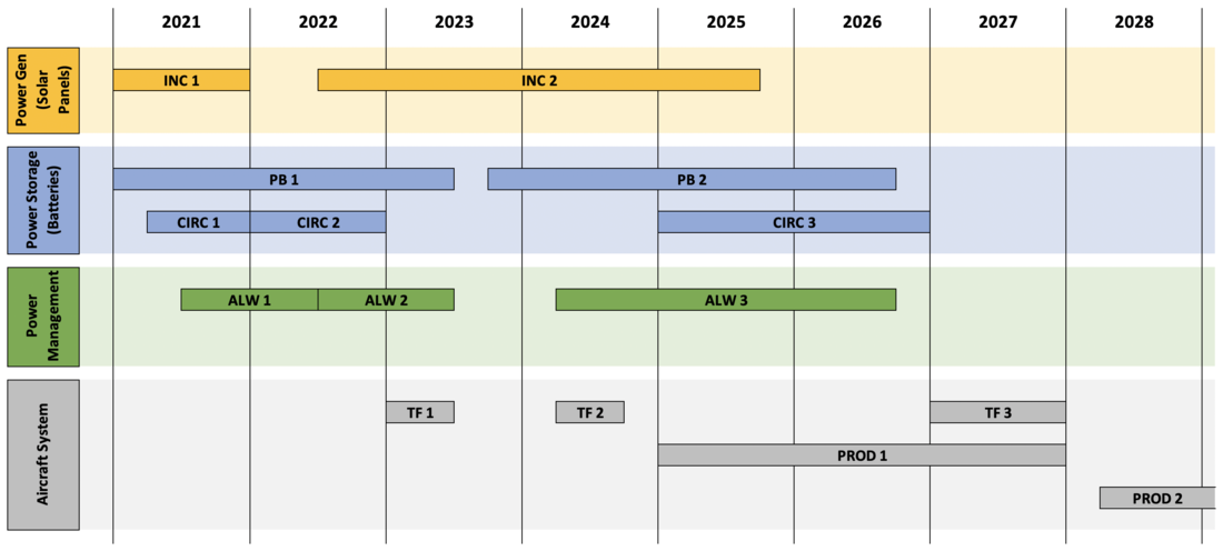
Solar Panel Performance (INC - Project "Incidence")
Incident angle of sunlight has a huge effect on the aircraft's ability to generate power. This project, in two phases, will determine how to optimize power generation for the available sunlight on station. Phase 1 will study effect of incidence angle on solar panel efficiency, and using different wing geometries and simulated flight conditions. Phase 2 will pursue solar panel development to allow for adequate power generation at all global locations throughout the year.
Power Storage
Excess power generation from the PV cells is useless without an efficient, deployable power storage system. These projects will address the build and use of batteries to keep the aircraft operating 24 hours a day.
Battery Energy Density (PB - Project "Peanut Butter")
The most crucial battery quality holding back proliferation of electric aircraft is energy density, the energy stored per unit mass. This project will assess different types of battery construction, including design work to fit the batteries into aircraft structures (wings, fuselage).
Recharge Cycling (CIRC - Project "Circadia")
The aircraft batteries must cycle daily in harsh temperature conditions that fluctuate daily and seasonally. This project will combine battery design with cycle testing, to ensure stable battery performance and explore modifications to enhance battery longevity and performance.
Power Management
Instrument Integration and Optimization (ALW - Project "Allowance")
The HALE UAV aircraft will be customizable, with power and weight budgets to be allocated according to the needs of each mission. However, we anticipate that many projects will choose from a common suite of surveillance techniques. Project Allowance will develop, improve, and test the integration of numerous common instruments (e.g. radar, infrared thermometer) to provide a power-optimized offering. There are two advantages to internally-optimized instrumentation. First, instrumentation can be optimized for power consumption to allow customers to maximize the available power (see Project Symbiosis). Second, HALE Storm can equip aircraft with these instrumentation packages to provide a more complete surveillance solution, and in doing so sell the aircraft at higher margins.
System Optimization (SYM - Project "Symbiosis")
To maximize the benefit of Project Allowance, we also will put significant effort into our system integration developments. This work will be classified as R&D rather than R&T, because it more directly associates with the demonstrators and final product development trending towards TRL 8 or 9. The focus of Symbiosis will be to optimize all aspects of the power management and flight control systems, in the forms they will be installed. [ Add targets for power consumption for propulsors, surveillance, system losses, charge retention, etc. if we keep this in the roadmap. ]
Flight Testing
Three flight tests will facilitate the transition of these technologies from TRL6 to product deployment. Each test will build on the last, but carry a unique focus.
Test Flight 1 (TF1) will test the full system against the theoretical and measured values for power generation, as determined in INC1. Test Flight 1 is slated for the first half of 2023.
Test Flight 2 (TF2) will focus on the enhancements produced through R&T work to date on the batteries and power management. This will include the technology outputs from PB1 (battery design), CIRC2 (battery performance), and ALW2 (instrumentation). Test Flight 2 is slated for the middle of 2024, allowing time to incorporate learnings from Test Flight 1, yet leaving a small buffer to fix any minor design issues before deployment of the first production aircraft (PROD1) in 2025.
Test Flight 3 (TF3) will incorporate the enhanced PV cell designs from INC2, as well as additional improvements across the board that are developed after the launch cutoffs for the first production aircraft (PROD1). This would cover battery design (PB2), battery performance (CIRC3), instrumentation performance (ALW3), and system integration (SYM3). The Test Flight 3 window will run for the full year 2027, to allow for multiple design tweaks during flight testing if necessary. This testing, when complete, will serve as the basis for the second production aircraft.
Technology Strategy Statement
Our target is to develop a High-Altitude Long-Endurance (HALE) Unmanned Aerial Vehicle (UAV) to be used for remote sensing and measurement of climate science phenomena beginning in 2025. HALE UAVs can offer superior monitoring capabilities compared to both low-altitude aircraft and satellites, with longer consistent on-station time and decreased atmospheric interference while remaining above tropospheric weather, if existing technological challenges around endurance and data collection can be solved. Therefore, our focus of R&T will come largely in two general stages. The first stage will focus on the flight vehicle, with developments to battery, PV cell, and charge cycling. This will support demonstration test flights in 2023 and 2024, and culminate with the first deployable product in 2025. The second stage of R&T will focus on instrumentation and data collection, optimizing these systems to more tightly integrate with the existing aerial platform for high reliability and low cost. The learnings and funding from the 2025 product will fuel developments for the second product, meant to be the more "final" offering with a target launch of 2028.
