Difference between revisions of "Large Ultra Lightweight Monolithic Mirros for Space Missions"
| (24 intermediate revisions by the same user not shown) | |||
| Line 1: | Line 1: | ||
Roadmap Creators: [https://www.linkedin.com/in/michal-delkowski/ | Michal Delkowski] | |||
Time Stamp: 4 December 2023 | |||
=Technology Roadmap Sections and Deliverables= | =Technology Roadmap Sections and Deliverables= | ||
| Line 81: | Line 85: | ||
After several efforts and failures, many experts concluded that to achieve such a low aerial density necessary are thermal and mechanical FOMs driven by enabling low sub-system level technologies, as highlighted in the table above (Structural and Thermal FOMs for 4MASM). "Although I’ve come to think that Stiffness and Areal Cost are more important" (NASA Ref. 6-7). | After several efforts and failures, many experts concluded that to achieve such a low aerial density necessary are thermal and mechanical FOMs driven by enabling low sub-system level technologies, as highlighted in the table above (Structural and Thermal FOMs for 4MASM). "Although I’ve come to think that Stiffness and Areal Cost are more important" (NASA Ref. 6-7). | ||
The figure shows the technical improvement in the density aerial over the year, including unsuccessful JWST targets and future necessary improvements. | |||
[[File:3LULMMTech.Improvement.jpg|800px]] | |||
Interesting developments were carried out for other mirrors, such as Herschel, the giant monolithic mirror (3.5 meters) for infrared astronomy missions manufactured in France. US companies began to work on SiC for space optics, including support coming from NASA. However, their primary focus was on SiC composites, and they failed to master the material properties, further abandoning these activities. The solution came by developing and manufacturing sintered silicon carbide in France, a very homogenous with low porosity and high mechanical strength. SiC powder is typically squeezed into solid blocks, where relatively soft blanks can be easily shaped into highly complex parts using computer-guided milling machines. The pieces are further placed into a furnace (approx. 2000°C) and baked into ceramics, then they become extremely hard and can be machined using diamond-headed grinding. The next important step was to invent the joining technology, which allowed the production of this gigantic mirror, as the SiC parts are typically small, with a maximum diameter of close to 1 meter achieved at that time. The French Nuclear Agency (CEA) developed the brazing joining technology that enabled 12 smaller segments to be joined together, thereby forming a 3.5 large mirror with an overall thickness of 3.5 mm and weight of 300 kg. The segments had to be shaped to optical precision with gaps between them of 10 microns. | Interesting developments were carried out for other mirrors, such as Herschel, the giant monolithic mirror (3.5 meters) for infrared astronomy missions manufactured in France. US companies began to work on SiC for space optics, including support coming from NASA. However, their primary focus was on SiC composites, and they failed to master the material properties, further abandoning these activities. The solution came by developing and manufacturing sintered silicon carbide in France, a very homogenous with low porosity and high mechanical strength. SiC powder is typically squeezed into solid blocks, where relatively soft blanks can be easily shaped into highly complex parts using computer-guided milling machines. The pieces are further placed into a furnace (approx. 2000°C) and baked into ceramics, then they become extremely hard and can be machined using diamond-headed grinding. The next important step was to invent the joining technology, which allowed the production of this gigantic mirror, as the SiC parts are typically small, with a maximum diameter of close to 1 meter achieved at that time. The French Nuclear Agency (CEA) developed the brazing joining technology that enabled 12 smaller segments to be joined together, thereby forming a 3.5 large mirror with an overall thickness of 3.5 mm and weight of 300 kg. The segments had to be shaped to optical precision with gaps between them of 10 microns. | ||
| Line 86: | Line 94: | ||
[[File:LULMMHerschel.jpg]] | [[File:LULMMHerschel.jpg]] | ||
However, the mirror achieved aerial density of the SiC blank less than 120 kg/m2, which is high compared to the further required progress. A surface shape test accuracy was better than 6 nm RMS, thickness inhomogeneity of the cladding layer was less than 5%, and the final surface figure error and roughness were 15.2 nm RMS and 0.8 nm RMS, respectively. | However, the mirror achieved aerial density of the SiC blank less than 120 kg/m2 [Ref. 28], which is high compared to the further required progress. A surface shape test accuracy was better than 6 nm RMS, thickness inhomogeneity of the cladding layer was less than 5%, and the final surface figure error and roughness were 15.2 nm RMS and 0.8 nm RMS, respectively. | ||
A material selection is crucial for very large mirrors and will be discussed in more detail in the technical model part. The mounting strategy and material properties must ensure the mirror will survive the launch and maintain its shape. The following properties and features can be concluded: | A material selection is crucial for very large mirrors and will be discussed in more detail in the technical model part. The mounting strategy and material properties must ensure the mirror will survive the launch and maintain its shape. The following properties and features can be concluded: | ||
| Line 144: | Line 152: | ||
Strategically we target large ultra-lightweight mirrors (4 m diameter and above), and thus we assume for our design: | Strategically we target large ultra-lightweight mirrors (4 m diameter and above), and thus we assume for our design: | ||
*Radius of curvature for optical face: 4m (goal, constant) | |||
*Stiffener height at center: below 20 mm (potential design variable that would become constant) | |||
*Stiffener height at outer rib: ≤ 50 mm (potential design variable that would become constant) | |||
*Constant sub-stiffener height: below 10 mm | |||
*Optical face: 1.2 mm (our design variable) | |||
*Rib thickness: ≤ 1mm (our design variable that would become constant) | |||
*Outer rib thickness: below 2 mm (our design variable that would become constant) | |||
*Back face thickness: ≤ 1mm (our design variable that would become constant) | |||
*Outer stiffener: below 2 mm (our design variable that would become constant) | |||
Material Selection | Material Selection | ||
Considering the rest of the targeted requirements (reference values), including: | Considering the rest of the targeted requirements (reference values), including: | ||
*Aerial density ≤10 [kg/ m2] | |||
*SFE at 1g | |||
*MSF, driven by the quilting effect and the aerial density requirement where an optical face sheet will be prone to generate quilting during manufacturing and polishing | |||
*Eigenfrequency > 80 Hz | |||
*Mechanical loads with a good mechanical strength | |||
and the previous lessons learned, the challenge is more mechanical, favoring structural FOM (earlier tradespace analysis). Furthermore, the Beryllium cannot fulfill optical requirements, including the required roughness of 1 nm rms. Therefore, we select the Boostec SiC® as our baseline. The earlier identified key performances (mechanical, optical, and thermal) and references targeted values that are affected by material and geometry and thus are linked to the decision variables. The table below outlines some reference values with earlier attempted or manufactured space mirrors. | and the previous lessons learned, the challenge is more mechanical, favoring structural FOM (earlier tradespace analysis). Furthermore, the Beryllium cannot fulfill optical requirements, including the required roughness of 1 nm rms. Therefore, we select the Boostec SiC® as our baseline. The earlier identified key performances (mechanical, optical, and thermal) and references targeted values that are affected by material and geometry and thus are linked to the decision variables. The table below outlines some reference values with earlier attempted or manufactured space mirrors. | ||
| Line 172: | Line 180: | ||
Figure: History of surface errors (top) and surface roughness (bottom) during the milling, grinding, polishing, and figuring phases. Also shown is the method of surface testing used: mechanical until the blank surface is specular, and optical afterward (Ref.9). | Figure: History of surface errors (top) and surface roughness (bottom) during the milling, grinding, polishing, and figuring phases. Also shown is the method of surface testing used: mechanical until the blank surface is specular, and optical afterward (Ref.9). | ||
Partial analytical derivatives of aerial density and WFE (see | Partial analytical derivatives of aerial density and WFE (see FOMs with driven equations: Aerial density=m/A, incl. relations of SFE and RMS= 1/3 (RMSx(𝐷x,𝐿x)+RMSy(𝐷x,𝐿x)+RMSz(𝐷x,𝐿1,𝐿x)) concerning the variables, but also other related performances such as specific stiffness are calculated and compared to the reference Herschel mirror. | ||
Aerial density | Aerial density; | ||
Simplified WFE for which further normalized sensitives are elaborated | Simplified WFE for which further normalized sensitives are elaborated; | ||
Simplified specific stiffness for which further normalized sensitives are elaborated | Simplified specific stiffness for which further normalized sensitives are elaborated; | ||
The defined parameters are driven by morphological matrix and detail variables, where each sub-technology and related performance with FOMs are connected. The figure shows the two FOM aerial densities and specific ratios, but also indirectly linked with optical SFE/WFE and mechanical performance. | The defined parameters are driven by morphological matrix and detail variables, where each sub-technology and related performance with FOMs are connected. The figure shows the two FOM aerial densities and specific ratios, but also indirectly linked with optical SFE/WFE and mechanical performance. | ||
| Line 188: | Line 196: | ||
==Financial Model== | ==Financial Model== | ||
An analysis was conducted to understand the financial prospects of ultra-lightweight mirror technology with future facilities to target all strategic drivers. The project will do it sequentially by addressing 1st target with FOMs for 2 m class space mirrors, after which the first sales will commence, then the 2nd target with FOMs for ≥4m class space mirrors, where the next revenues will be generated. Finally, the project will approach the 3rd target to construct the company with facilities capable of E2E manufacturing large space mirrors. The R&D funding reflects only the internal financing. As many government/agencies call programs, the remaining R&D budget will be captured, including demonstration, which is not reflected in this analysis. The analysis presented forecasts a timeline for the project to generate a "profit" or break-even point as the value of sales in 2041 for the company with facilities. It has to be noted that earlier break events could be approached with manufacturing mirrors using sub-contractors and suppliers. Nevertheless, the budget is reinvested to develop our own company with facilities and future larger incomes. Consequently, the NPV analysis for each strategic driver alone or the overall approach would generate a profit. Furthermore, this considers the conservative assumption as more budget could be acquired from external sources. | |||
[[File:3LULMMFinance.jpg|800px]] | |||
'''Future Scenario<br>''' | |||
2023-2027 Developed 2-m class large-ultra lightweight monolithic mirrors (aerial density ≤10 kg/m 2 and targeted FOMs: thermo-optical and mechanical performance) using next-generation technologies for Earth Observation and Science mission. | |||
2028 mission adoption and qualification | |||
2029 mission launch with in-orbit operation start | |||
2028 – 2032 Developed 4-m class large-ultra lightweight monolithic mirrors (aerial density ≤10 kg/m 2 and targeted FOMs: thermo-optical and mechanical performance) using next-generation technologies for Earth Observation and Science missions. | |||
2033 mission adoption and qualification | |||
2035 mission launch with in-orbit operation start | |||
2037 developed a joining methodology for large-area mirrors | |||
2038 developed large area reflecting coatings for monolithic mirrors | |||
2040 company with E2E capabilities to be established with production-ready | |||
2041, the first large monolithic space mirrors were sold to the market | |||
Total Cash Flow: | |||
• Large ultra-lightweight monolithic space mirrors (2-m and ≥ 4m class) and company with facilities for E2E manufacturing budget currently at ~$5.9M (FY'23), including all costs offset by sales. | |||
Cost Assumptions: | |||
• R&D Expenditures – Large Ultralightweight Monolithic Mirrors for Space Missions budget currently at ~$8M (FY'23), which fluctuates based on the strategic target driver (2-m class space mirrors ~$0.9M (FY'23), ≥ 4m class space mirrors ~$3.2M (FY'23) + rest fluctuating during development and facility constructions). | |||
• Facility Construction Costs: anticipated future construction costs based on knowledge, possible co-funding, and current facilities ~$3.7M (FY'23) | |||
• Facility Operating Costs: anticipated future operating costs based on knowledge and current facilities ~$0.6M (FY'23), | |||
The sale costs are anticipated based on the knowledge, current market, and literature [Ref. 5-24], as shown in the figure below, the example of notional cost per m2 of mirror blank manufacture and optical figuring as | |||
a function of mirror diameter. The additional cost of the mirrors and control system must be added to that cost. | |||
[[File:3LULMMFiguringCost.jpg|600px]] | |||
The figure reflects the costs (FY1995'-1998') with much lower performance mirrors requiring less precision and shorter polishing time. Furthermore, it includes terrestrial mirrors. Therefore, they are mainly informative to provide the starting range. | |||
==List of Demonstrator Projects== | ==List of Demonstrator Projects== | ||
Large Ultra Lightweight Monolithic Mirrors for Space Missions proposed projects to be funded include: | |||
[[File:3LULMMDemonstration.jpg|1200px]] | |||
==Key Publications, Presentations and Patents== | ==Key Publications, Presentations and Patents== | ||
| Line 206: | Line 264: | ||
Gloesener et al., reveal the primary mirror design, manufacturing, and performance built for the science EUCLID mission (launched in 2023 towards the L2 point to study the dark universe) in collaboration between Airbus and Boostec (France), using unique silicon carbide material. It consists of a 1.2 m-class telescope with accommodated instruments. Harnish et al., | Gloesener et al., reveal the primary mirror design, manufacturing, and performance built for the science EUCLID mission (launched in 2023 towards the L2 point to study the dark universe) in collaboration between Airbus and Boostec (France), using unique silicon carbide material. It consists of a 1.2 m-class telescope with accommodated instruments. Harnish et al., provide insight into the progress realized in the frame of the funded program by ESA, where Dornier Satellitensystem (now part of Airbus) developed the unique form of SiC ceramic (C/SiC) with reduced brittleness and negligible shrinkage during processing. This has shown potential for large ultra-lightweight monolithic mirrors with desired optical performance thanks to ion beam figuring. Ealey et al., show ultra-lightweight silicon carbide mirrors with an areal density below 10kg/mm2 with a size as large as 1.2 meters in diameter. The optical finishing is below 10 angstroms RMS, and the complex structures are addressed with triangular, square, or hexagonal core geometries and web thickness as thin as 0.015 inches. | ||
Three patents are related to the design and manufacturing of mirrors: | Three patents are related to the design and manufacturing of mirrors: | ||
1) Advanced Mirrors Utilizing Polymer-Derived-Ceramic Mirror Substrates: presents the methods, systems, and processes to manufacture lightweight mirrors, among other optical components. This is achieved using polymer-derived ceramics (PCDs), such as silicon oxycarbide (SioC). It claims to be applicable for both terrestrial and space applications. | 1) Advanced Mirrors Utilizing Polymer-Derived-Ceramic Mirror Substrates (Type CPCI, CPC G 11 B 5/8404, ID: US 20170050890 A1): presents the methods, systems, and processes to manufacture lightweight mirrors, among other optical components. This is achieved using polymer-derived ceramics (PCDs), such as silicon oxycarbide (SioC). It claims to be applicable for both terrestrial and space applications. | ||
2) METHOD OF TREATING JOINT IN CERAMIC ASSEMBLY: demonstrates a method to form improved sealed joints between two or more shaped ceramic structures, which are necessary to create the mirror (e.g., joint the ribs and/or front face with a back face). This is achieved by converting at least a portion of one or more of silicon, a silicon alloy, and a silicon compound of the joint to silicon nitride and/or silicon carbide to provide increased chemical resistance for the joint. The ceramic structures can compromise silicon carbide. | 2) METHOD OF TREATING JOINT IN CERAMIC ASSEMBLY (Type CPCI, CPC B 32 B 38/0036, Corning Incorporated, ID: US 20140334869 A1): demonstrates a method to form improved sealed joints between two or more shaped ceramic structures, which are necessary to create the mirror (e.g., joint the ribs and/or front face with a back face). This is achieved by converting at least a portion of one or more of silicon, a silicon alloy, and a silicon compound of the joint to silicon nitride and/or silicon carbide to provide increased chemical resistance for the joint. The ceramic structures can compromise silicon carbide. | ||
3) Methods Of Manufacturing Mirrors: shows the methods of forming a mirror by bonding a facesheet to a core structure using a specific adhesive formulation. The joining methodology is essential to allow the manufacturing of ultra-lightweight, durable, and robust optical mirrors. | 3) Methods Of Manufacturing Mirrors (Eagle Technology LLC, Type CPCI, CPC B 29 C 65/525, ID: US 11780173 B1): shows the methods of forming a mirror by bonding a facesheet to a core structure using a specific adhesive formulation. The joining methodology is essential to allow the manufacturing of ultra-lightweight, durable, and robust optical mirrors. | ||
==Technology Strategy Statement== | ==Technology Strategy Statement== | ||
Our target is to develop the first Large Ultralightweight Monolithic Mirrors for space missions with end-to-end manufacturing capabilities by 2040. | |||
To achieve this, our strategic roadmap is divided into three phases as shown in the high-level roadmap chart below. The first phase targets leverage sub-technologies to produce Large 2-m class ultralightweight (aerial density ≤10 kg/m2) monolithic mirrors by 2027 and in-orbit demonstration in 2029. The second phase is following this success and leveraging capabilities with upscaling to produce the first Large ≥4-m class ultralightweight (aerial density ≤10 kg/m2) monolithic space mirrors by 2022 with the in-orbit demonstration in 2035. The third and final phase establishes the company with end-to-end manufacturing facilities to produce these large ultralightweight monolithic space mirrors; it secures and increases company know-how. | |||
[[File:3LULMMTechStrategy.jpg|1000px]] | |||
==References== | ==References== | ||
| Line 265: | Line 327: | ||
22. Michel Bougoin et al., The SiC primary mirror of the EUCLID telescope, ICSO 2016 International Conference on Space Optics, Biarritz, France 18–21 October 2016. | 22. Michel Bougoin et al., The SiC primary mirror of the EUCLID telescope, ICSO 2016 International Conference on Space Optics, Biarritz, France 18–21 October 2016. | ||
23. Michel Bougoin and Jérôme Lavenac, From HERSCHEL to GAIA, 3-meter class SiC space optics, BOOSTEC (MERSEN group), Zone Industrielle , 65460 Bazet, France. | |||
24. Philip Stahl, MSFC, Overview and Recent Accomplishments of Advanced Mirror Technology Development (AMTD) for Very Large Space Telescopes, SPIE Conference on UV/Optical/IR Space Telescopes and Instrumentation, 2013. | |||
25. Lu Sun et al., Multi-Objective Parametric Optimization Design for Mirrors Combined with Non-Dominated Sorting Genetic Algorithm, Appl. Sci. 2023, 13(5), 3346; https://doi.org/10.3390/app13053346. | |||
26. Mejiun Zhan et al., Design and Optimization for Mounting Primary Mirror with Reduced Sensitivity to Temperature Change in an Aerial Optoelectronic Sensor, Sensors 2021, 21(23), 7993; https://doi.org/10.3390/s21237993. | |||
27. Yanjun Qu et al., Lightweight Design of Multi-Objective Topology for a Large-Aperture Space Mirror, Appl. Sci. 2018, 8(11), 2259; https://doi.org/10.3390/app8112259. | |||
28. Xuejun Zhang et al., Challenges and strategies in high-accuracy manufacturing of the world’s largest SiC aspheric mirror, Light: Science & Applications volume 11, Article number: 310 (2022). | |||
Latest revision as of 02:05, 5 December 2023
Roadmap Creators: | Michal Delkowski
Time Stamp: 4 December 2023
Technology Roadmap Sections and Deliverables
This is a technology roadmap for:
- 3LULMMFSM - Large Ultra-Lightweight Monolithic Mirrors for Space Missions
Large-Ultra Lightweight Monolithic Mirrors (LULMM) (also enable segmented designs for space missions) - Mirrors are enabling technology for space based telescopes. Primary mirror size and quality is directly traceable to telescope performance. Every engineering advancement in space mirror technology has resulted in improved earth observation and science performance. Future large scale optical instruments for Earth Observation and Science missions will require very large primary mirrors with extreme light weighting. There has been significant technical evolution realized over the last years. However, the current level of light weighting is reaching the limit of classical techniques and decreasing optical performances due to side efforts, causing mission concepts with active correction capabilities which could be simplified by using alternative techniques for lighter and stiffer primary mirrors. The weight can be drastically reduced with designs based on a thin optical face sheets, which are attached to a stiff and lightweight support structures (e.g. honeycomb…).
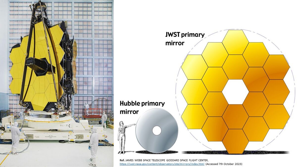
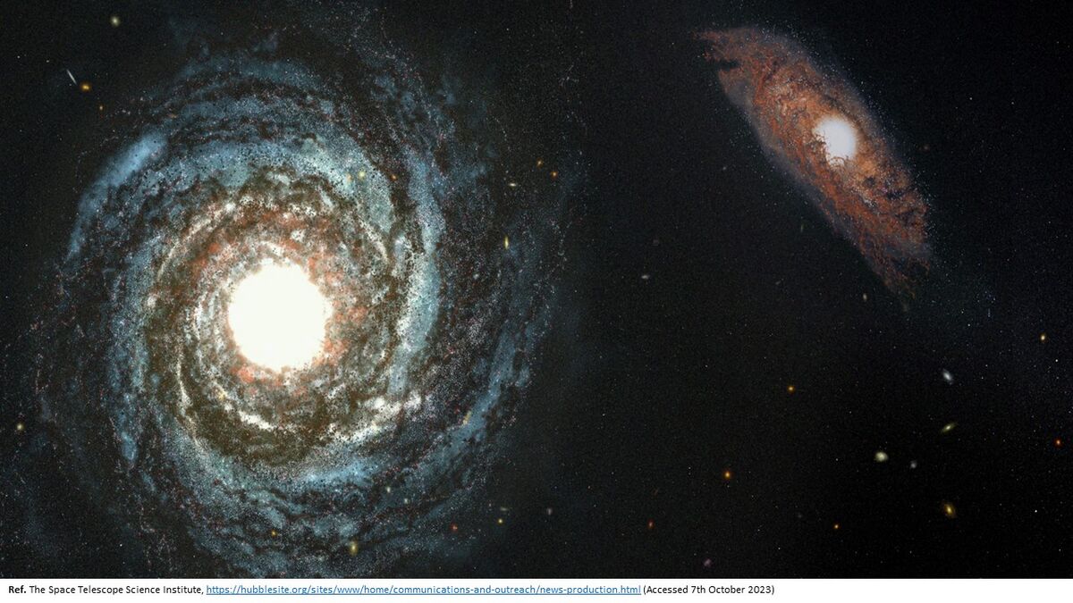
Ultra-precision mirrors are setting the space telescope design. Rare are the components whose design lies at such optimal crossroads between 3 major engineering fields (optical, thermal, and mechanical) while challenging manufacturing and integration capacities in these fields. The recent spotlight on JWST's magnificently gigantic golden primary mirror and the incredible pictures it helps create (figure below) has brought mirror design to the forefront of the public eye and the engineers. Yet, the subtle and skillful art and efforts that underlie a genuinely successful mirror design are not always prominent. This roadmap addresses space mirror technologies' previous, current, and future needs.
Roadmap Overview
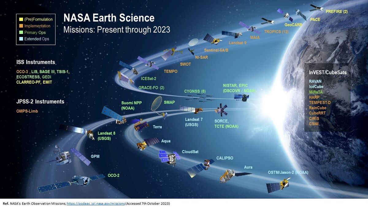
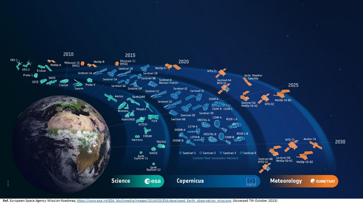
Images show the Science and Earth Observation programs from the European Space Agency (ESA) and the National Aeronautics and Space Administration (NASA), indicating the needs for space mirror technologies.
Some critical elements enabling the LULMM include:
- large aperture, low-areal density and ultra-high stiff mirror substrates
- support structure
- mid/high-spatial frequency figure error
- segment-to-segment gap phasing
- mirror segment edges
- modeling and validation
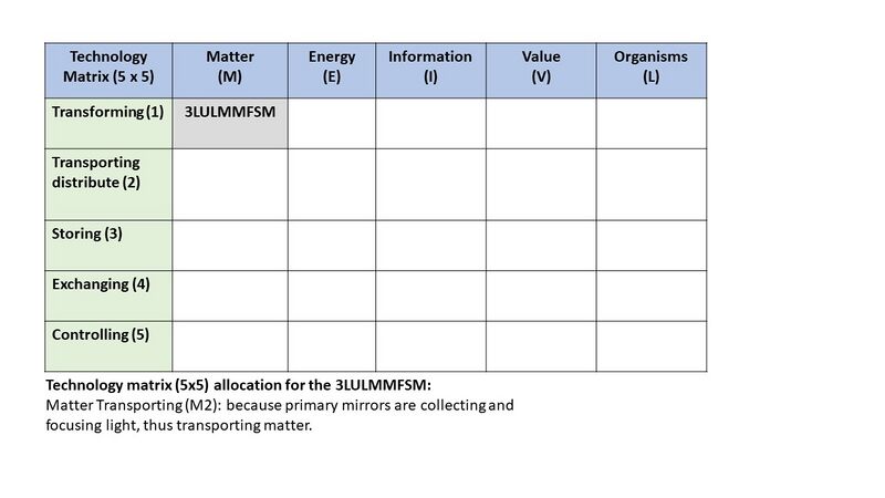
Figure is showing the 5x5 Technology Matrix [Ref.1] with the position of 3LULMMFSM.
A significant amount of developments was carried out for ultra lightweight mirrors. Ball Aerospace demonstrated Beryllium mirrors with an aerial density as low as 9.8 kg/m2. However , this was for a diameter 0.5m and without guaranteeing sufficient stiffness in order to survive the launch, similar as for the JWST where the mirrors have to be re-designed with a final aerial density of 28 kg/m2, while the initial concept was aiming to achieve even below 15 kg/m2.
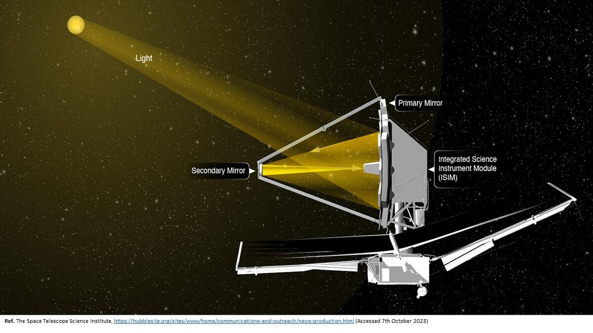
A primary mirror of JWST has 6.5 meters (21 feet 4 inches) across, which is needed to measure the light from distant galaxies. Building a mirror this large was challenging, even for use on the ground. This size of the mirror had never before been launched into space, in comparison the Hubble Space Telescope 2.4 meter mirror is shown, which would be too heavy concept to launch into orbit for the JWST. For the JWST the stiff and light mirror was essential, thus having very low aerial density to enable this mission concept and objectives.
Technology advancements are progressing and now future must be prepared to enable areal densities less than 10 kg/m2, for large mirrors located in an optical system entrance cavity (e.g., scan mirror, primary mirror). This would enable key factor in the production of large monolithic mirrors (>2 meters) and segmented designs usable for EO and JWST successor like missions, thereby securing high resolution imaging capability for space systems in e.g., geostationary orbit.
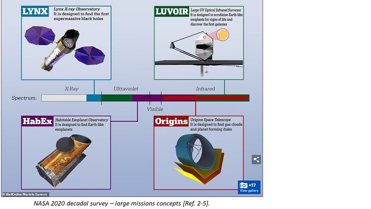
Space community, industry and agencies are addressing this gap seeking for next technological developments to enable low aerial density, ultra-high performance mirrors [Ref. 2-5] for:
- GEO mid.-high resolution observation
- Science missions
- Agile flat mirrors (Fast-steering, scanners…)
- ...
Design Structure Matrix (DSM) Allocation
The 3LULMM tree shows us that a Large Ultra-Lightweight Monolithic Mirror is part of a telescope structure (2TEL) to enable Earth Observation and Science Missions (1EOSM).
The other elements of telescope structure, Earth Observation, and Science Missions are not shown here. The DSM and tree both show that 3LULMM requires the following technologies at the subsystems level: 4RUSO Optical Facesheets, 4MBSS Support Structure, 4MASM Materials, 4JTEC Joining Methodologies, 4PMGP Precise Machining and Polishing, 4ISMC Isostatic Mounts, 4ULOC Optical Coatings, and 4MAVP Modeling with Validation. Each level 4 subsystem also depends on other 4 level subsystem technologies, which hilights high interdependencies and challenges.
Roadmap Model using OPM
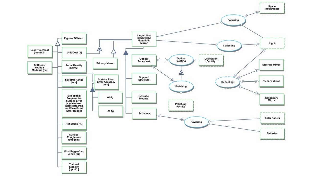
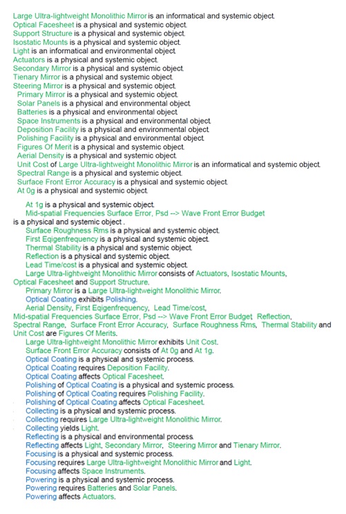
The Object-Process-Diagram (OPD) of the 3LULMM Large Ultra-Lightweight Monolithic Mirros is provided in the figure below. This diagram captures the main object of the roadmap, its various processes and instrument objects, and its characterization by Figures of Merit (FOMs). The more detailed elements are already unfolded to show some sub-processes with supporting instrument objects.
An Object-Process-Language (OPL) description of the roadmap scope is auto-generated in the Object Process Methodology (OPM) and given below. It reflects the same content as the in the OPD, but in a formal natural language.
Figures of Merit
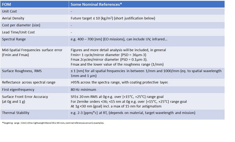
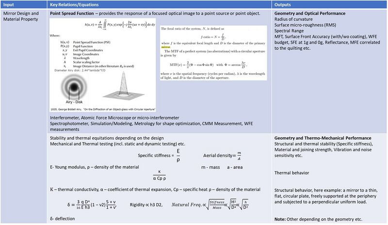
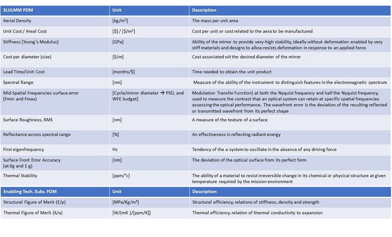
The table below shows a list of FOM by which Large Ultra-Lightweight Monolithic Mirrors (LULMM) can be assessed.FOM on this list relates specifically to the Earth Observation and Science Missions and targeted low aerial density with necessary thermal, optical, and mechanical performance. Consequently, additional FOM from enabling technologies (structural and thermal) related to the material selection (4MASM) that would drive the mirror design and implementation are highlighted.
The table below gives some exemplary nominal reference values.
Important FOMs to achieve desired thermo-opto-mechanical performance are driven by generic equations/relations, design, and modeling. These are depicted in the table below.
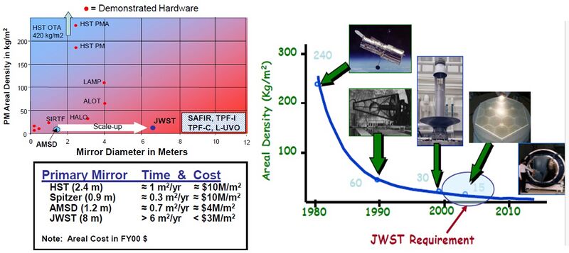
Space agencies, notably NASA, carried out intensive developments for primary mirrors. Philipp Stahl when joining NASA, said [Ref 6-7], "When I joined NASA is 1999, the overriding mantra for Space Telescopes was Areal Density, Cost & Schedule". We can see in the figure below the targeted aerial density for the JWST with earlier demonstrators realized in the frame of the AMSD study. Several companies were working on parallel concepts, including KODAK or Ball Aerospace (recently acquired by BAE Systems), who built Beryllium mirrors with an aerial density as low as 9.8 kg/m2. However, this did not provide sufficient stiffness to upscale and survive the launch. Also, despite the initial requirements, the JWST mirrors have to be re-designed with a final aerial density of 28 kg/m2, while the initial concept aimed to achieve even below 15 kg/m2.
After several efforts and failures, many experts concluded that to achieve such a low aerial density necessary are thermal and mechanical FOMs driven by enabling low sub-system level technologies, as highlighted in the table above (Structural and Thermal FOMs for 4MASM). "Although I’ve come to think that Stiffness and Areal Cost are more important" (NASA Ref. 6-7).
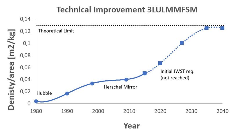
The figure shows the technical improvement in the density aerial over the year, including unsuccessful JWST targets and future necessary improvements.
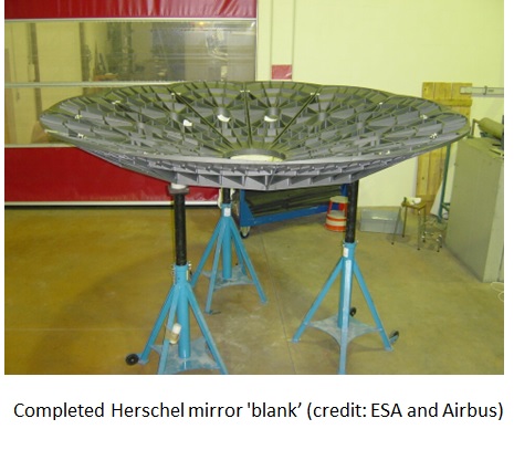
Interesting developments were carried out for other mirrors, such as Herschel, the giant monolithic mirror (3.5 meters) for infrared astronomy missions manufactured in France. US companies began to work on SiC for space optics, including support coming from NASA. However, their primary focus was on SiC composites, and they failed to master the material properties, further abandoning these activities. The solution came by developing and manufacturing sintered silicon carbide in France, a very homogenous with low porosity and high mechanical strength. SiC powder is typically squeezed into solid blocks, where relatively soft blanks can be easily shaped into highly complex parts using computer-guided milling machines. The pieces are further placed into a furnace (approx. 2000°C) and baked into ceramics, then they become extremely hard and can be machined using diamond-headed grinding. The next important step was to invent the joining technology, which allowed the production of this gigantic mirror, as the SiC parts are typically small, with a maximum diameter of close to 1 meter achieved at that time. The French Nuclear Agency (CEA) developed the brazing joining technology that enabled 12 smaller segments to be joined together, thereby forming a 3.5 large mirror with an overall thickness of 3.5 mm and weight of 300 kg. The segments had to be shaped to optical precision with gaps between them of 10 microns.
However, the mirror achieved aerial density of the SiC blank less than 120 kg/m2 [Ref. 28], which is high compared to the further required progress. A surface shape test accuracy was better than 6 nm RMS, thickness inhomogeneity of the cladding layer was less than 5%, and the final surface figure error and roughness were 15.2 nm RMS and 0.8 nm RMS, respectively.
A material selection is crucial for very large mirrors and will be discussed in more detail in the technical model part. The mounting strategy and material properties must ensure the mirror will survive the launch and maintain its shape. The following properties and features can be concluded:
- Mechanical: stiffness, density, and ductility, which drive the mechanical stability of the optical system and are limiting factors for lightweight architectures
- Thermal: low CTE, thermal stability, infrared emissivity, and conductivity, which allow the avoidance of thermal gradients and secure stability
- Optical: achievable surface roughness associated with polishing capabilities and targeted spectral wavelengths
- Manufacturability, cost, and schedule: substrate materials that are affordable and available to allow the production of very large mirrors
Alignment with Company Strategic Drivers
Based on market analysis, FOMs, and future needs, the "company" strategy is to develop the concept of next-generation large ultra-lightweight mirrors for space missions, which are located in an optical system entrance cavity. This will enable future mirrors to be usable for EO and science missions, securing high-resolution imaging capability for space systems.
Positioning of Company vs. Competition
The large primary mirrors for space business are expensive and challenging to produce hardware, requiring highly skillful companies. Thus, there are only a few capable of providing these capabilities. The global telescope mirror market is witnessing many emerging trends, especially the increasing demand for lightweight mirrors, which enable space missions, improve handling launch capabilities, and often reduce cost. There is a growing preference for advanced materials, but there is no one material able to cover every mission. Depending on the required mechanical and optical performance on one hand and the thermal environment on the other hand, one material may exhibit better features than the others. There are some major market players, including Advanced Glass Industries (AGI, US), Corning (US, New York), Galvoptics (United Kingdom), BRD Optical (Germany), Telescopi Italiani (Italy), Bursh Welman (United States) who provide more standard and lower performance materials such as fused silica and borosilicate. Corning is one of the leading players in the mirrors, but various fields such as optical communications, display, and environmental technologies.
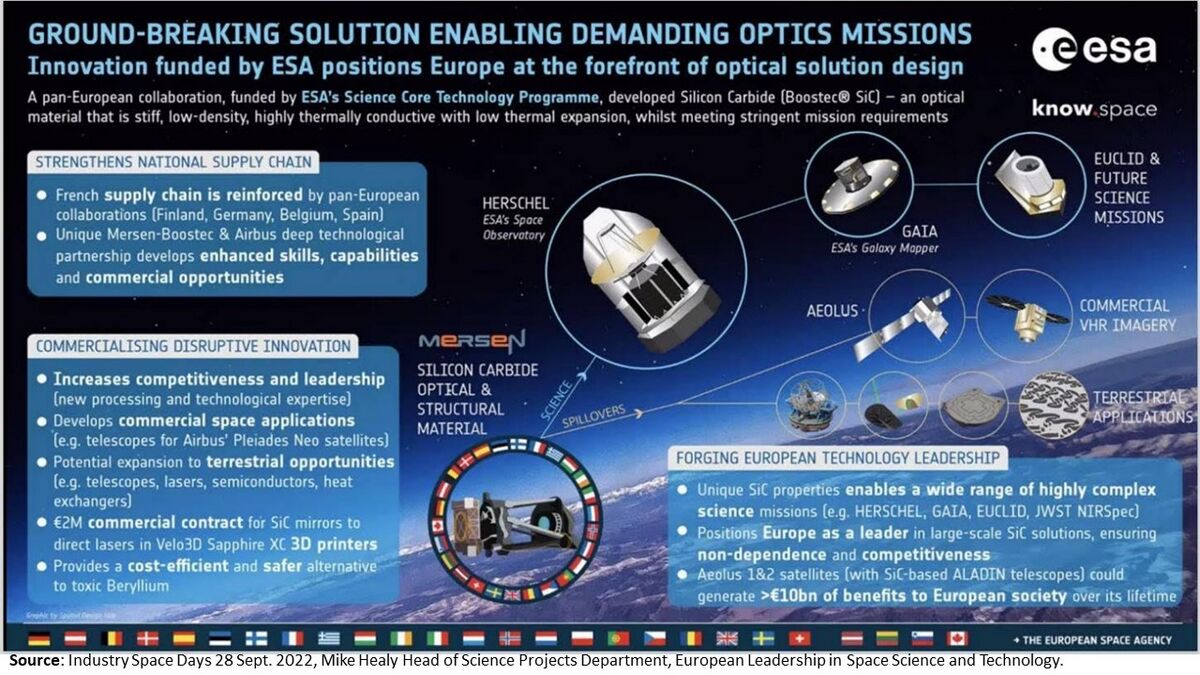
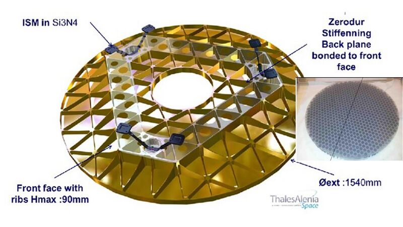
As earlier discussed, there are several critical technologies to enable the manufacturing of large ultra-lightweight mirrors for space missions. One of the technologies that combined several sub-technologies, such as high-stiffness of mirrors substrates, MFS, joining, etc., became the specific Silicon Carbide (SiC) developed by Boostec Mersen (called BOOSTEC® SIC) in collaboration with Airbus, including one the key and first application for Herschel Mission ( 3.5 m Sic Mirror). At that time, the next generation of EO and Science missions required a significant increase in performance on a different FOM (structural, thermal…) to mainstream the mirror product. The company follows the attacker and pioneer strategy, introducing a new disruptive and enabling technology without which the subsequent infrared astronomy missions could not occur. The technology was sought for this giant Herschel mirror, where classical materials such as aluminum and carbon fiber were unsuitable for performance, while glass materials were too heavy. Regarding silicon carbide for space missions, Boostec has oligopoly as their material, which has other properties compared to other available silicon carbides, and knowledge with long-term partners makes it unique. Boostec SiC® is enabling highly demanding requirements to design mechanically and thermally ultra-stable space optics, thereby appearing to be a material of choice, even unavoidable for some space telescopes. Some examples include Sentinel-2, the recently launched Euclid mission to study the dark Universe and Aeolus for Earth Observation, NIRSpec large spectrograph for NASA JWST, and many other telescope mirrors. The ESA figure below from Space Days shows the “ground-breaking solution” enabled by a unique and deep technological partnership between Mersen Boostec & Airbus, positioning Europe as a world leader in large-scale SiC solutions.
Moving further to the space mirrors for high-performance science and earth observation missions, we can distinguish other materials. Another one is Beryllium, which is typically considered for mirrors in cryogenic applications, as it combines a high stiffness with low density and high thermal conductivity. However, the CTE at room temperature is very high (around 11 ppm) and thus unsuitable for thermally stable structures across high-temperature ranges. This drops to around zero at cryogenic conditions; hence, it has been selected as the substrate for the James Webb Space Telescope (JWST) mirrors. Consequently, its contribution to the overall applications and space market is low, including its toxic nature.
The other related FOM, which favors thermal efficiency (CTE close to 0) and caused duopoly in the mirrors for science and high-resolution EO missions, is related to Zerodur® material and ULE® (low expansion glass-ceramics), but having worse properties.This unique low thermal expansion glass material is offered by Schott GmbH, a worldwide leading company whose strategy is focus on reinventing specialty glass and glass-ceramics, with three key goals: “to be pioneers, develop high-tech solutions with our customers, and assume responsibility for society and the environment.” This material has an excellent polishing capabilities and can be manufactured in a variety of sizes and shapes, from tiny prisms to meter-sized mirror blanks. Both Boostec and Schott dominated the space mirror market for high-demanding space missions.
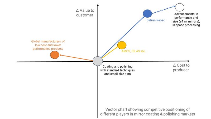
The highly skillful mirrors would only be achievable with coating and precise polishing. Integrating polishing techniques enables exact finishing and higher accuracy in producing mirror blanks. The increasing popularity of space and astronomy is fueling the demand for mirrors in the coming years. The Safran REOSC is the world leader in high-performance optomechanical systems, focusing on mirrors and including uniquely developed solutions for Boostec Silicon Carbide® and Schott Zerodur®. Their current capabilities include polishing, controlling, and coating high precision optics to the nanometer accuracy and large sizes up to 4-meter diameter, which is not achievable by competitors. Independently of the industrial setup, Safran REOSC is usually a favorable candidate for coating and polishing, thus making an oligopoly in this area. A good example is even the European Space Observatory (ESO) gigantic telescope (ELT), the largest telescope ever built in Chile, which consists of Boostec Silicon Carbide® used for the reference structure of its M4 adaptive optics and also its fast tip/tilt M5 folding mirror. The other mirrors are made of Schott Zerodur®, whereas Silicon Carbide and Zerodur were coated and polished by Safran REOSC with their know-how and developed enabling technologies. Likewise, Mersen Boostec and Schott, Safran REOSC has been pursuing the pioneering strategy for many decades and constantly adapts to the market being on the front end.
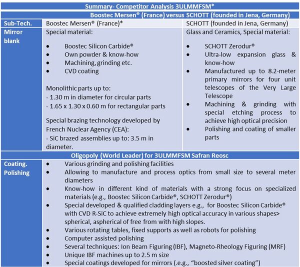
The table shows a summary of the competitor analysis with a focus on the large-ultralightweight monolithic mirrors for space missions and distinguish among: • Duopoly between Boostec Mersen® and SCHOTT (founded in Jena, Germany), who use two unique materials suitable for high-performance scientific and EO missions. • Safran Reosc oligopoly in handling and processing large mirrors with uniquely developed coating and polishing technologies.
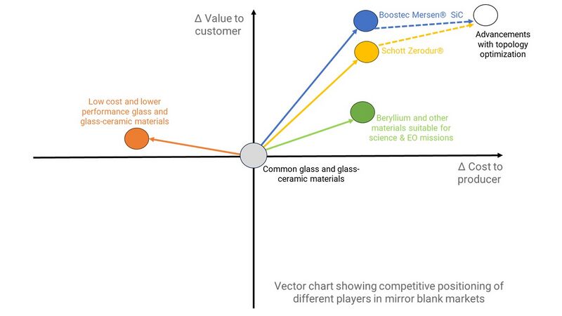
For mirror blanks, other indirect and direct competitors usually focus on more common glass or glass-ceramic materials (BK7, fused silica…), whereas for polishing and coating other companies are limited to more classical materials and smaller dimensions (.e.g. Magneto-Rheology Figuring <1 m mirrors).
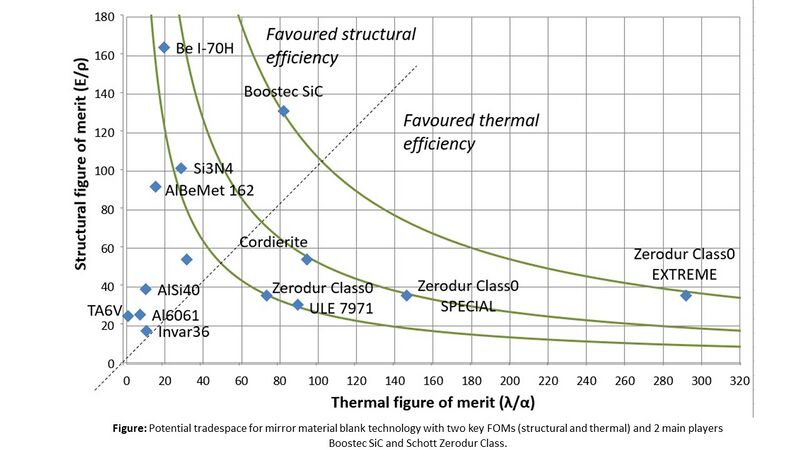
Various FOMs and enabling sub-technologies were hilighted earlier, and the first tradespace is realized here.The figure below shows the relation of enabling material mirror blank technology (Structural vs Thermal FOM). The green curves represent the iso-performance when considering the product of the two figures of merit. At first order, it brings in evidence two families of material: (1) Boostec SiC® and Schott Zerodur® demonstrate the best characteristics for mirrors, and (2) Beryllium, Si3N4, ULE, and Cordierite are materials of interest as well but with lower global performance. There is not a unique material able to cover every mission. Depending on the required mechanical and optical performance on one hand and the thermal environment on the other hand, one material may exhibit better features than the others. However, this unveil driving technological strategical advantages. Moreover, the Figure shows the figures of merit, split into two domains by the dotted line. 1 – The upper left favors structural efficiency, so we find materials with high stiffness, low density, and generally good strength capabilities but which are more sensitive to the thermal environment due to their “nonnull” CTE. Their CTE depends on the temperature; some can also demonstrate very low CTE in cryogenic environments (i.e., Beryllium, SiC). 2 – The second one on the lower right favors thermal efficiency. We will find material with CTE close to 0. So, they won’t be sensitive to the thermal environment but generally demonstrate lower strength and stiffness.
Technical Model
We analyzed some enabling sub-technologies for large-ultralightweight monolithic mirrors within the generated tradespace and now focus on selected two critical FOMs in our 3LULMMFSM technical model for sensitivity analysis. We noted that the previous attempts to bring down the aerial density ≤10 [kg/ m2] failed, primarily due to the inability to survive the launch loads. This was associated with material, shape, and other factors. Apart from the targeted aerial density, we aim to achieve earlier specified performances (optical: SFE, WFE…, mechanical: first eigenfrequency….).
To achieve the targeted performance, we focus on the mirror sandwich concept because it is well known that the honeycomb structure with closed skins is the best design to optimize the stiffness/mass ratio.
Strategically we target large ultra-lightweight mirrors (4 m diameter and above), and thus we assume for our design:
- Radius of curvature for optical face: 4m (goal, constant)
- Stiffener height at center: below 20 mm (potential design variable that would become constant)
- Stiffener height at outer rib: ≤ 50 mm (potential design variable that would become constant)
- Constant sub-stiffener height: below 10 mm
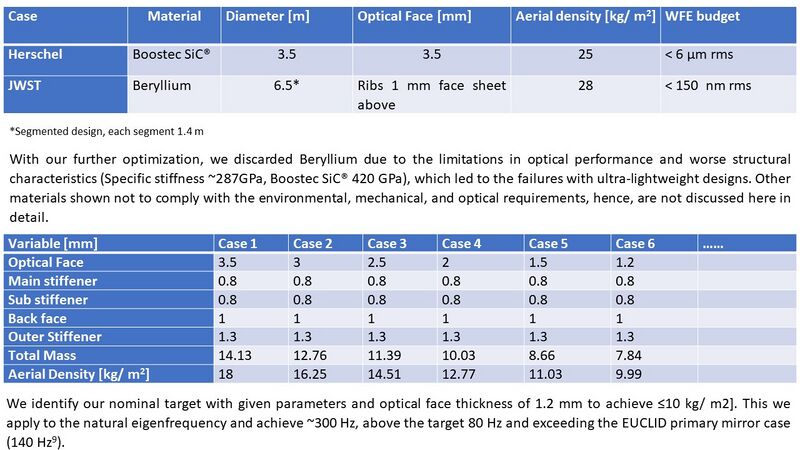
- Optical face: 1.2 mm (our design variable)
- Rib thickness: ≤ 1mm (our design variable that would become constant)
- Outer rib thickness: below 2 mm (our design variable that would become constant)
- Back face thickness: ≤ 1mm (our design variable that would become constant)
- Outer stiffener: below 2 mm (our design variable that would become constant)
Material Selection Considering the rest of the targeted requirements (reference values), including:
- Aerial density ≤10 [kg/ m2]
- SFE at 1g
- MSF, driven by the quilting effect and the aerial density requirement where an optical face sheet will be prone to generate quilting during manufacturing and polishing
- Eigenfrequency > 80 Hz
- Mechanical loads with a good mechanical strength
and the previous lessons learned, the challenge is more mechanical, favoring structural FOM (earlier tradespace analysis). Furthermore, the Beryllium cannot fulfill optical requirements, including the required roughness of 1 nm rms. Therefore, we select the Boostec SiC® as our baseline. The earlier identified key performances (mechanical, optical, and thermal) and references targeted values that are affected by material and geometry and thus are linked to the decision variables. The table below outlines some reference values with earlier attempted or manufactured space mirrors.
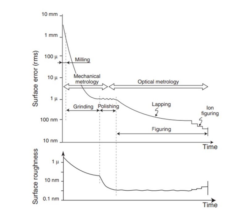
The thermal vacuum cycling would not be an issue for the proposed case, as the monolithic SiC mirror with the fixture is isostatic mounted and, from the known studies and designs (GAIA, Sentinel-2 NG MSRI Mirror, Euclid), is not critical for strength. The WFE under 1g is calculated according to the driven equations, while the WFE = 2 x SFE with the WFE (rms) criteria 80 nm and including a maximum of 30 nm for astigmatism, the achieved overall WFE <50 nm and including coefficient of <20 nm.For the surface roughness, the well-known and developed CVD SiC cladding layer with Ion beam figuring will be used, capable of achieving ≤1nm RMS. The figure below shows the history of surface roughness with evolved technical advancements.
Figure: History of surface errors (top) and surface roughness (bottom) during the milling, grinding, polishing, and figuring phases. Also shown is the method of surface testing used: mechanical until the blank surface is specular, and optical afterward (Ref.9).
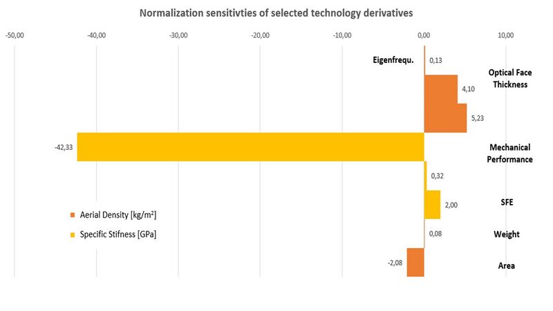
Partial analytical derivatives of aerial density and WFE (see FOMs with driven equations: Aerial density=m/A, incl. relations of SFE and RMS= 1/3 (RMSx(𝐷x,𝐿x)+RMSy(𝐷x,𝐿x)+RMSz(𝐷x,𝐿1,𝐿x)) concerning the variables, but also other related performances such as specific stiffness are calculated and compared to the reference Herschel mirror.
Aerial density; Simplified WFE for which further normalized sensitives are elaborated; Simplified specific stiffness for which further normalized sensitives are elaborated;
The defined parameters are driven by morphological matrix and detail variables, where each sub-technology and related performance with FOMs are connected. The figure shows the two FOM aerial densities and specific ratios, but also indirectly linked with optical SFE/WFE and mechanical performance.
Summarized major improved performances/FOMS: Herschel vs proposed 3LULMMFSM.
Financial Model
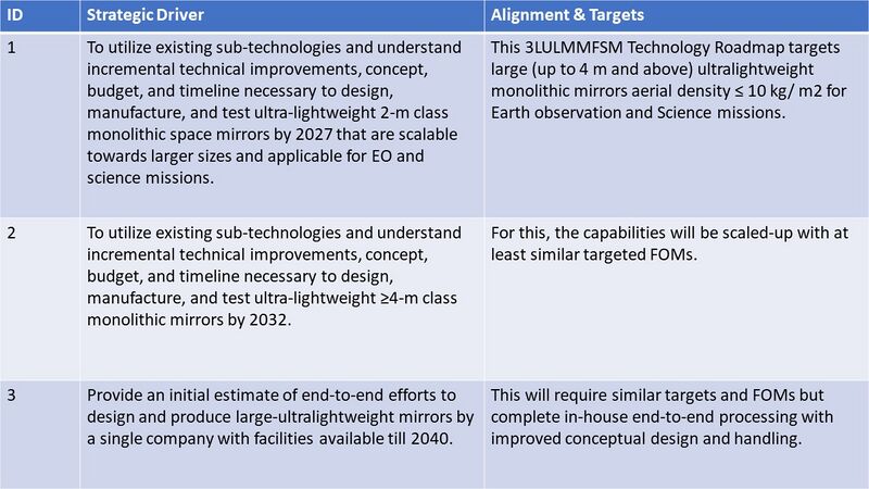
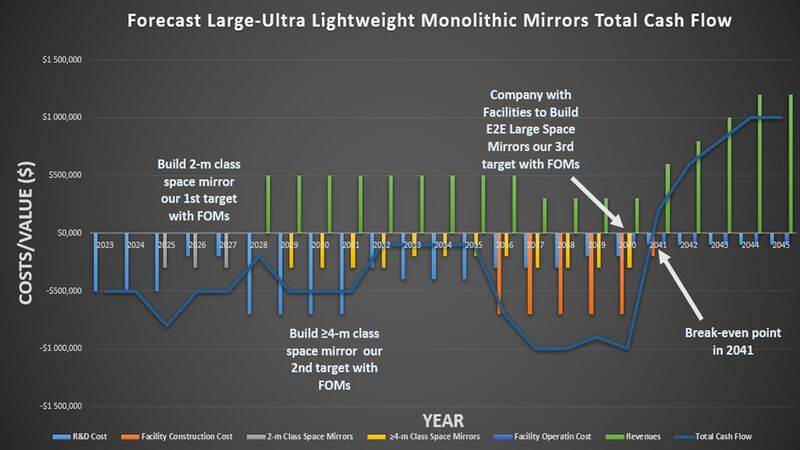
An analysis was conducted to understand the financial prospects of ultra-lightweight mirror technology with future facilities to target all strategic drivers. The project will do it sequentially by addressing 1st target with FOMs for 2 m class space mirrors, after which the first sales will commence, then the 2nd target with FOMs for ≥4m class space mirrors, where the next revenues will be generated. Finally, the project will approach the 3rd target to construct the company with facilities capable of E2E manufacturing large space mirrors. The R&D funding reflects only the internal financing. As many government/agencies call programs, the remaining R&D budget will be captured, including demonstration, which is not reflected in this analysis. The analysis presented forecasts a timeline for the project to generate a "profit" or break-even point as the value of sales in 2041 for the company with facilities. It has to be noted that earlier break events could be approached with manufacturing mirrors using sub-contractors and suppliers. Nevertheless, the budget is reinvested to develop our own company with facilities and future larger incomes. Consequently, the NPV analysis for each strategic driver alone or the overall approach would generate a profit. Furthermore, this considers the conservative assumption as more budget could be acquired from external sources.
Future Scenario
2023-2027 Developed 2-m class large-ultra lightweight monolithic mirrors (aerial density ≤10 kg/m 2 and targeted FOMs: thermo-optical and mechanical performance) using next-generation technologies for Earth Observation and Science mission.
2028 mission adoption and qualification
2029 mission launch with in-orbit operation start
2028 – 2032 Developed 4-m class large-ultra lightweight monolithic mirrors (aerial density ≤10 kg/m 2 and targeted FOMs: thermo-optical and mechanical performance) using next-generation technologies for Earth Observation and Science missions.
2033 mission adoption and qualification
2035 mission launch with in-orbit operation start
2037 developed a joining methodology for large-area mirrors
2038 developed large area reflecting coatings for monolithic mirrors
2040 company with E2E capabilities to be established with production-ready
2041, the first large monolithic space mirrors were sold to the market
Total Cash Flow:
• Large ultra-lightweight monolithic space mirrors (2-m and ≥ 4m class) and company with facilities for E2E manufacturing budget currently at ~$5.9M (FY'23), including all costs offset by sales.
Cost Assumptions:
• R&D Expenditures – Large Ultralightweight Monolithic Mirrors for Space Missions budget currently at ~$8M (FY'23), which fluctuates based on the strategic target driver (2-m class space mirrors ~$0.9M (FY'23), ≥ 4m class space mirrors ~$3.2M (FY'23) + rest fluctuating during development and facility constructions).
• Facility Construction Costs: anticipated future construction costs based on knowledge, possible co-funding, and current facilities ~$3.7M (FY'23)
• Facility Operating Costs: anticipated future operating costs based on knowledge and current facilities ~$0.6M (FY'23),
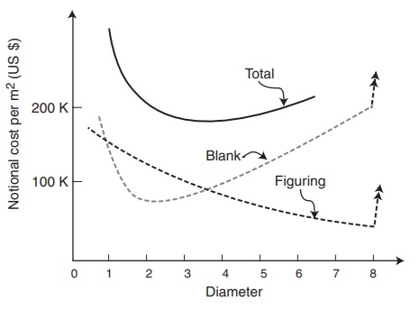
The sale costs are anticipated based on the knowledge, current market, and literature [Ref. 5-24], as shown in the figure below, the example of notional cost per m2 of mirror blank manufacture and optical figuring as
a function of mirror diameter. The additional cost of the mirrors and control system must be added to that cost.
The figure reflects the costs (FY1995'-1998') with much lower performance mirrors requiring less precision and shorter polishing time. Furthermore, it includes terrestrial mirrors. Therefore, they are mainly informative to provide the starting range.
List of Demonstrator Projects
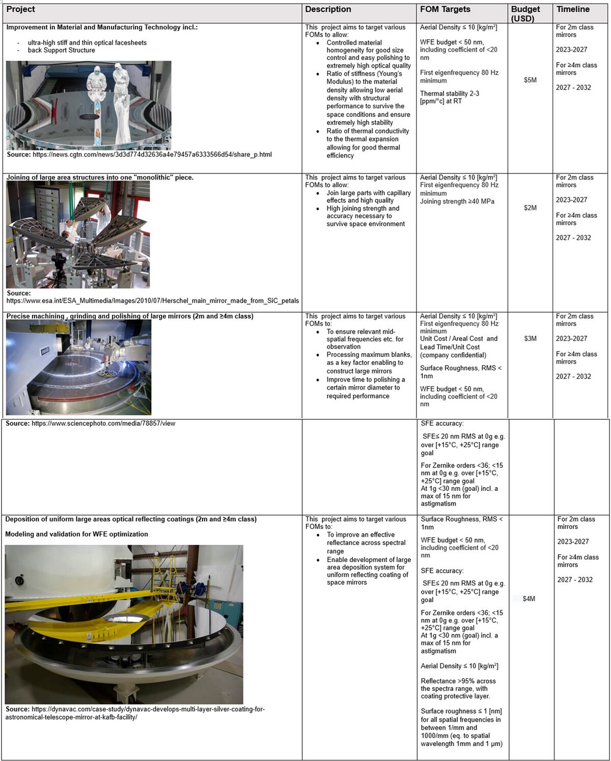
Large Ultra Lightweight Monolithic Mirrors for Space Missions proposed projects to be funded include:
Key Publications, Presentations and Patents
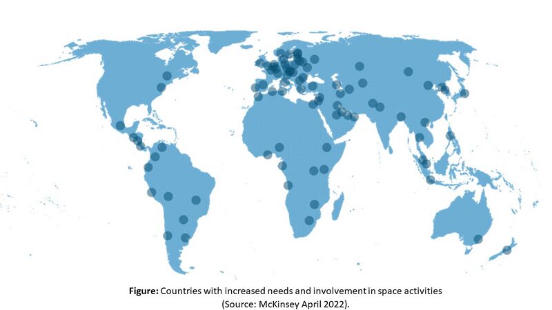
There are several patents and publications, including those that target ultralightweight monolithic mirror design and technologies (see references).The figure shows the map of countries that have started to be involved in space activities, particularly on space optics or requiring them.
All papers and patents are directly associated with roadmapped technology and its critical elements. The referred sources and research were used. The U.S. Trademark and Patent Office was checked, but it is limited and usually does not provide complete information; the World Intellectual Property Organization’s (WIPO) international patent database was also used to understand the patent landscape better. Furthermore, the consultancy with IP management and advisors was realized.
Gey et al., reveal the recent progress Safran Reosc (France) realized in the development of lightweight glass ceramic space optics, in particular with Airbus working on the Silicon Carbide technology (e.g., the recent Euclid mission to study the dark matter). It describes the developments in glassy ultralightweight optics, e.g., in MERLIN or Kompsat-7 missions, and thin shells. Vecchi et al., demonstrate a method to manufacture thin shells of glass for optics in future space telescopes, especially very thin optical face sheets, which would allow the low aerial density of the mirrors. The method also covers making large optics with polishing capabilities to achieve the desired performance. Devillier et al., present the progress realized by Thales Alenia Space and Thales SESO, who focus on the new concept of sizeable lightweight mirrors using Zerodur® material. It demonstrates two meter mirrors with an aerial density of 17kg/m2 and a Zerodur® hybrid mirror with an aerial density of 25kg/m2, respectively. The design consisted of a closed-back assembly.
Gloesener et al., reveal the primary mirror design, manufacturing, and performance built for the science EUCLID mission (launched in 2023 towards the L2 point to study the dark universe) in collaboration between Airbus and Boostec (France), using unique silicon carbide material. It consists of a 1.2 m-class telescope with accommodated instruments. Harnish et al., provide insight into the progress realized in the frame of the funded program by ESA, where Dornier Satellitensystem (now part of Airbus) developed the unique form of SiC ceramic (C/SiC) with reduced brittleness and negligible shrinkage during processing. This has shown potential for large ultra-lightweight monolithic mirrors with desired optical performance thanks to ion beam figuring. Ealey et al., show ultra-lightweight silicon carbide mirrors with an areal density below 10kg/mm2 with a size as large as 1.2 meters in diameter. The optical finishing is below 10 angstroms RMS, and the complex structures are addressed with triangular, square, or hexagonal core geometries and web thickness as thin as 0.015 inches.
Three patents are related to the design and manufacturing of mirrors:
1) Advanced Mirrors Utilizing Polymer-Derived-Ceramic Mirror Substrates (Type CPCI, CPC G 11 B 5/8404, ID: US 20170050890 A1): presents the methods, systems, and processes to manufacture lightweight mirrors, among other optical components. This is achieved using polymer-derived ceramics (PCDs), such as silicon oxycarbide (SioC). It claims to be applicable for both terrestrial and space applications.
2) METHOD OF TREATING JOINT IN CERAMIC ASSEMBLY (Type CPCI, CPC B 32 B 38/0036, Corning Incorporated, ID: US 20140334869 A1): demonstrates a method to form improved sealed joints between two or more shaped ceramic structures, which are necessary to create the mirror (e.g., joint the ribs and/or front face with a back face). This is achieved by converting at least a portion of one or more of silicon, a silicon alloy, and a silicon compound of the joint to silicon nitride and/or silicon carbide to provide increased chemical resistance for the joint. The ceramic structures can compromise silicon carbide.
3) Methods Of Manufacturing Mirrors (Eagle Technology LLC, Type CPCI, CPC B 29 C 65/525, ID: US 11780173 B1): shows the methods of forming a mirror by bonding a facesheet to a core structure using a specific adhesive formulation. The joining methodology is essential to allow the manufacturing of ultra-lightweight, durable, and robust optical mirrors.
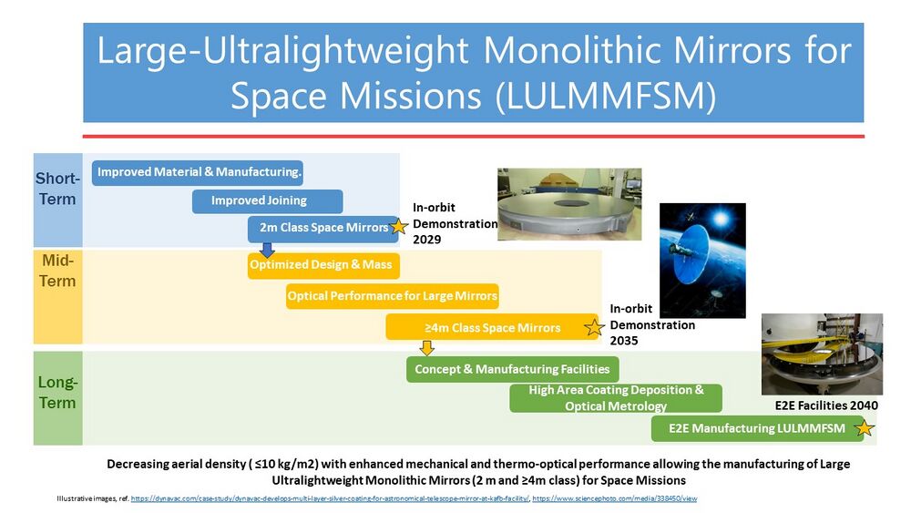
Technology Strategy Statement
Our target is to develop the first Large Ultralightweight Monolithic Mirrors for space missions with end-to-end manufacturing capabilities by 2040. To achieve this, our strategic roadmap is divided into three phases as shown in the high-level roadmap chart below. The first phase targets leverage sub-technologies to produce Large 2-m class ultralightweight (aerial density ≤10 kg/m2) monolithic mirrors by 2027 and in-orbit demonstration in 2029. The second phase is following this success and leveraging capabilities with upscaling to produce the first Large ≥4-m class ultralightweight (aerial density ≤10 kg/m2) monolithic space mirrors by 2022 with the in-orbit demonstration in 2035. The third and final phase establishes the company with end-to-end manufacturing facilities to produce these large ultralightweight monolithic space mirrors; it secures and increases company know-how.
References
1. Olivier L. De Weck, Technology Roadmapping and Development, A Quantitative Approach to the Management of Technology, Springer Nature 2022.
2. Geyl, R. and Ruch, E., 2021, June. Progress in ultra-lightweight glass ceramic space optics. In International Conference on Space Optics—ICSO 2020 (Vol. 11852, pp. 79-89). SPIE., https://doi.org/10.1117/12.2599147
3. Vecchi, G., Basso, S., Civitani, M., Ghigo, M., Pareschi, G. and Salmaso, B., 2019. Thin glass shells for active optics for future space telescopes. CEAS Space Journal, 11(4), pp.533-541., https://doi.org/10.1007/s12567-019-00259-7
4. C. Devilliers, C. Du Jeu, V. Costes, A. Suau, N. Girault, L. Cornillon, “New design and new challenge for space large ultralightweight and stable Zerodur© mirror for future high resolution observation instruments”,Proceedings Volume 10563, International Conference on Space Optics — ICSO 2014; 105631I (2017) https://doi.org/10.1117/12.2304187
5. P. Gloesener, F. Wolfs, M. Cola, E. Wachtelaer, C. Flebus, “Optics for EUCLID telescope: challenges and developments”, Proceedings Volume 11451, Advances in Optical and Mechanical Technologies for Telescopes and Instrumentation IV; 114510L (2020) https://doi.org/10.1117/12.2562807.
6. Stahl, H. Philip, 50 Years to NASA M.irror Technology Development: From Hubble to JWST and Beyond, 6th International Symposium on Advanced Optical Manufacturing and Testing Technologies. (AOMATT 2012)
7. Stahl, H. Philip, Advanced ultraviolet, optical, and infrared mirror technology development for very large space telescope, Journal of Astronomical Telescopes, Instruments, and Systems, 6(2). 025001 (2020), doi: 10.1117/1.JATIS.6.2.025001.
8. Dave Baiocchi, H. Philip Stahl, Enabling Future Space Telescopes: Mirror Technology Review and Development Roadmap.
9. P. Y. Bely, The Design and Construction of Large Optical Telescopes, Springer (2003)
10. Feinberg, Lee, et. al., “NASA Capability Road Map (CRM) 4: Advanced Telescope and Observatory (ATO)”, NASA capability road map report (2007).
11. Kaifu, N. et. al., “The first light of the Subaru telescope: a new infrared image of the Orion Nebula”, Publ. of the Astronomical Society of Japan, vol. 52, (2000).
12. J. Nelson, “Segmented mirror telescopes”, Optics in Astrophysics, 198, (2006). DOI: 10.1007/1-4020-3437-7.
13. H. Philip Stahl, P. Sumrall, R. Hopkins, “Ares V launch vehicle: An enabling capability for future space science missions,” Acta Astronautica, In Press, Corrected Proof, Available online 27 February 2009, ISSN 0094-5765, DOI: 10.1016/j.actaastro.2008.12.017.
14. Stahl, H. Philip, "Design study of an 8 meter monolithic mirror uv/optical space telescope", SPIE Astronomy Conference, Marseille, France, June 2008.
15. H. Philip Stahl, “Mirror technology roadmap for optical/IR/FIR space telescopes”, Proc. SPIE, 6265 (2006), DOI: 10.1117/12.671958
16. M. W. Werner, et. al., “The Spitzer Space Telescope mission,” The Astrophysical Journal Supplement Series, 154, (2004), DOI: 10.1086/422992.
17. P. Yoder Jr., Opto-mechanical Systems Design, 2nd ed., Marcel Dekker (1993)
18. Advanced Mirrors Utilizing Polymer-Derived-Ceramic Mirror Substrates, Type CPCI, CPC G 11 B 5/8404, ID: US 20170050890 A1
19. METHOD OF TREATING JOINT IN CERAMIC ASSEMBLY, Type CPCI, CPC B 32 B 38/0036, Corning Incorporated, ID: US 20140334869 A1.
20. Methods Of Manufacturing Mirrors, Eagle Technology LLC, Type CPCI, CPC B 29 C 65/525, ID: US 11780173 B1.
21. Herald Keeper, Glass Ceramic Market, Glass Ceramics Market Shaping Innovations for Diverse Applications Overview & Forecast 2023-2030 | Schott, Corning(Eurokera), Nippon Electric Glass https://heraldkeeper.com/view/2981474/glass-ceramics-market-shaping-innovations-for-diverse-applications-overview-forecast-2023-2030-schott-corningeurokera-nippon-electric-glass.html (Accessed November 2023).
22. Michel Bougoin et al., The SiC primary mirror of the EUCLID telescope, ICSO 2016 International Conference on Space Optics, Biarritz, France 18–21 October 2016.
23. Michel Bougoin and Jérôme Lavenac, From HERSCHEL to GAIA, 3-meter class SiC space optics, BOOSTEC (MERSEN group), Zone Industrielle , 65460 Bazet, France.
24. Philip Stahl, MSFC, Overview and Recent Accomplishments of Advanced Mirror Technology Development (AMTD) for Very Large Space Telescopes, SPIE Conference on UV/Optical/IR Space Telescopes and Instrumentation, 2013.
25. Lu Sun et al., Multi-Objective Parametric Optimization Design for Mirrors Combined with Non-Dominated Sorting Genetic Algorithm, Appl. Sci. 2023, 13(5), 3346; https://doi.org/10.3390/app13053346.
26. Mejiun Zhan et al., Design and Optimization for Mounting Primary Mirror with Reduced Sensitivity to Temperature Change in an Aerial Optoelectronic Sensor, Sensors 2021, 21(23), 7993; https://doi.org/10.3390/s21237993.
27. Yanjun Qu et al., Lightweight Design of Multi-Objective Topology for a Large-Aperture Space Mirror, Appl. Sci. 2018, 8(11), 2259; https://doi.org/10.3390/app8112259.
28. Xuejun Zhang et al., Challenges and strategies in high-accuracy manufacturing of the world’s largest SiC aspheric mirror, Light: Science & Applications volume 11, Article number: 310 (2022).
