Difference between revisions of "Hypersonic Transport Vehicles"
| (109 intermediate revisions by 2 users not shown) | |||
| Line 1: | Line 1: | ||
=Roadmap & System Overview= | =Roadmap & System Overview= | ||
Hypersonic transport vehicles are a type of aircraft from the wider group of hypersonic systems. Hypersonic systems are all vehicles that operate in the flight regime where aerodynamic heating becomes significant, typically thought of as flight faster than Mach 5. Such systems include most atmospheric entry vehicles, some orbital launch vehicles, and several types of ballistic or maneuvering missiles. Hypersonic transport vehicles aim to move personnel and cargo from place to place much faster than traditional transonic or even supersonic aircraft. With a commercial application, this would be accomplished with the aim of generating profit for the company providing the transport service. | Roadmap Creators: Daniel Gochenaur & Chris Tommila, 5 December 2023 | ||
Hypersonic transport vehicles (1HTV) are a type of aircraft from the wider group of hypersonic systems. Hypersonic systems are all vehicles that operate in the flight regime where aerodynamic heating becomes significant, typically thought of as flight faster than Mach 5. Such systems include most atmospheric entry vehicles, some orbital launch vehicles, and several types of ballistic or maneuvering missiles. Hypersonic transport vehicles aim to move personnel and cargo from place to place much faster than traditional transonic or even supersonic aircraft. With a commercial application, this would be accomplished with the aim of generating profit for the company providing the transport service. | |||
This page presents a technology roadmap for hypersonic transport vehicles. Hypersonic systems rely upon a myriad of sub-technologies that have allowed us to perfect flight at lower Mach numbers. Several of these existing technologies will be discussed here, in addition to a critical review of the technology advances still required to enable commercial hypersonic transport vehicles. | This page presents a technology roadmap for hypersonic transport vehicles. Hypersonic systems rely upon a myriad of sub-technologies that have allowed us to perfect flight at lower Mach numbers. Several of these existing technologies will be discussed here, in addition to a critical review of the technology advances still required to enable commercial hypersonic transport vehicles. | ||
| Line 46: | Line 48: | ||
The FOMs above are described mathematically, including expected nominal values in the table below. | The FOMs above are described mathematically, including expected nominal values in the table below. | ||
[[File: | [[File:FOMs3.jpg|600px|center]] | ||
It is possible to review historic trends of the FOMs by plotting the FOM value of a given system over time. In the figure below, we plot the maximum velocity of various existent commercial aircraft and projected commercial aircraft concepts. | It is possible to review historic trends of the FOMs by plotting the FOM value of a given system over time. In the figure below, we plot the maximum velocity of various existent commercial aircraft and projected commercial aircraft concepts. | ||
| Line 54: | Line 56: | ||
The practical maximum flight speed for commercial aircraft is indicated at Mach 10, or approximately 7,700 mph. This limit exists because the time savings of supersonic and hypersonic flight become very limited at very high Mach numbers, as the vehicle spends the vast majority of a given flight accelerating and subsequently decelerating from its intended cruise speed. Reviewing the figure above, we argue that hypersonic commercial transport systems are in the incubation stage of their lifecycle. At present, no such vehicles exist, but the various research demonstrations show that we are approaching a point where hypersonic commercial transit can become a reality. Further, we are likely at the stagnation point of progress on traditional subsonic commercial vehicles. As such, for customers with enough capital to afford higher speed travel, hypersonic transport vehicles will likely eventually disrupt the commercial aviation market. If the timeline projected by the various concept vehicles is to be trusted, this disruption should occur in the early 2030s. | The practical maximum flight speed for commercial aircraft is indicated at Mach 10, or approximately 7,700 mph. This limit exists because the time savings of supersonic and hypersonic flight become very limited at very high Mach numbers, as the vehicle spends the vast majority of a given flight accelerating and subsequently decelerating from its intended cruise speed. Reviewing the figure above, we argue that hypersonic commercial transport systems are in the incubation stage of their lifecycle. At present, no such vehicles exist, but the various research demonstrations show that we are approaching a point where hypersonic commercial transit can become a reality. Further, we are likely at the stagnation point of progress on traditional subsonic commercial vehicles. As such, for customers with enough capital to afford higher speed travel, hypersonic transport vehicles will likely eventually disrupt the commercial aviation market. If the timeline projected by the various concept vehicles is to be trusted, this disruption should occur in the early 2030s. | ||
It is important to note that achieving higher speed flight is driven by underlying technology advances and differences in aircraft design. These differences are visible in the image below, which shows example transonic, supersonic, and hypersonic aircraft. Clearly, the higher speed vehicles are becoming more slender, and the degree of coupling of the subcomponents (i.e. the wings, fuselage, and propulsion devices) is becoming much higher. | |||
[[File:Aircraft_Comparison.png|900px|center]] | |||
=Alignment with Company Strategic Drivers= | =Alignment with Company Strategic Drivers= | ||
[[File: | The figure below shows the alignment between 1HTV technology FOM targets and the company strategic drivers. This figure also provides an approximate timeline for implementation of company strategy. | ||
[[File:StrategicDrivers.png|600px|center]] | |||
=Positioning of Company vs Competition= | =Positioning of Company vs Competition= | ||
The figure below provides an overview of the range and cruise velocity performance of historical and current competitors in the market in the commercial air transportation market. In general, range and velocity are inversely related. However, it is difficult to draw a realistic Pareto frontier because of the technical immaturity of competing concepts in the market. Operational systems are shown in orange on the figure below but all represent subsonic or supersonic transport systems. The hypersonic systems shown in grey are all notional systems that have not published design specifications and have not demonstrated mature propulsion or thermal protection technologies to support their projected performance. In general, the company will drive towards the utopia point maximizing both range and velocity. Velocity, in this case is a useful proxy for total flight time. | |||
[[File:RangeVsMachPareto.PNG|500px|center]] | |||
=Technical Model= | =Technical Model= | ||
| Line 68: | Line 75: | ||
[[File:HypersonicMorphMatrix.PNG|600px|center]] | [[File:HypersonicMorphMatrix.PNG|600px|center]] | ||
=== | These tradeoffs listed above are indicated on a commercial hypersonic aircraft concept from Hermeus in the image below [20]. | ||
[[File:HyperVehicle_MorphMatrix.png|700px|center|Image credit [20]]] | |||
===FOM Sensitivities=== | |||
Technical models are developed for the FOMs of aircraft range and aircraft velocity in the subsections below. Calculation of the dimensional and normalized sensitivity values is performed using the baseline values shown in the table below. | Technical models are developed for the FOMs of aircraft range and aircraft velocity in the subsections below. Calculation of the dimensional and normalized sensitivity values is performed using the baseline values shown in the table below. | ||
[[File: | [[File:InputTableHyper_V2.PNG|550px|thumb|center|Table of FOM sensitivity input values]] | ||
∗M. Robert and D. Brewster, “Hypersonic cruise aircraft propulsion integration study, volume 2,” Sep. 1979, https://ntrs.nasa.gov/citations/19800006816.<br> | ∗M. Robert and D. Brewster, “Hypersonic cruise aircraft propulsion integration study, volume 2,” Sep. 1979, https://ntrs.nasa.gov/citations/19800006816.<br> | ||
∗∗Dillon, J. L. and Pittman, J. L., “Aerodynamic Characteristics at Mach 6 of a Wing-Body Concept for a Hypersonic Research Airplane,” NASA Technical Paper 1249, Aug. 1978, https://ntrs.nasa.gov/api/citations/19780022112/downloads/19780022112.pdf. | |||
====Aircraft Range==== | ====Aircraft Range==== | ||
As with propeller and jet powered aircraft, the range of a hypersonic aircraft is calculated using the Breguet range equation from the aircraft velocity ''v'', specific fuel consumption of the engine ''SFC'', lift-to-drag ratio ''L/D'' and the ratio of the initial to final weight of the vehicle ''Wi/Wf''. The difference between the initial and final weight of the aircraft is equal to the weight of fuel consumed. The Breguet range equation is the following: | As with propeller and jet powered aircraft, the range of a hypersonic aircraft is calculated using the Breguet range equation from the aircraft velocity ''v'', specific fuel consumption of the engine ''SFC'', lift-to-drag ratio ''L/D'' and the ratio of the initial to final weight of the vehicle ''Wi/Wf''. The difference between the initial and final weight of the aircraft is equal to the weight of fuel consumed. The Breguet range equation is the following: | ||
[[File:Brug.png|150px|center]] | |||
Using baseline values for the variables of the Breguet range equation, we can calculate numerical values for the sensitivity of range to a subset of variables. Note, this simplification of the range equation does not include the variation in v, SFC and L/D during the climb and descent phases. | |||
[[File:rangesense.png|550px|center]] | |||
A tornado diagram showing the normalized range sensitivity values is provided below. | A tornado diagram showing the normalized range sensitivity values is provided below. | ||
[[File:RangeSensitivity.png|550px|center]] | [[File:RangeSensitivity.png|550px|center]] | ||
The diagram shows that range is most sensitive to initial weight, and therefore propellant weight. Range is equally sensitive to SFC, velocity and L/D. The range of the hypersonic aircraft considered is 2 orders of magnitude more sensitive to velocity than the “traditional” subsonic turbojet considered in class and is 3 times more sensitive to SFC. This increased sensitivity highlights the challenges in mission, vehicle and engine design for hypersonic commercial transport. | The diagram shows that range is most sensitive to initial weight, and therefore propellant weight. Range is equally sensitive to SFC, velocity and L/D. The range of the hypersonic aircraft considered is 2 orders of magnitude more sensitive to velocity than the “traditional” subsonic turbojet considered in class and is 3 times more sensitive to SFC. This increased sensitivity highlights the challenges in mission, vehicle and engine design for hypersonic commercial transport. | ||
| Line 85: | Line 102: | ||
[[File:Velocity_Derivation.PNG|100px|center]] | [[File:Velocity_Derivation.PNG|100px|center]] | ||
As such, we have expressed the velocity as a function of thrust, drag coefficient, flow density, and reference area. Ignoring the reference area, the velocity sensitivity to vehicle thrust, drag coefficient, and air density is expressed by taking the derivative with respect to each variable. The below table provides the resultant sensitivity equations along with the dimensional sensitivity result. | As such, we have expressed the velocity as a function of thrust, drag coefficient, flow density, and reference area. Ignoring the reference area, the velocity sensitivity to vehicle thrust, drag coefficient, and air density is expressed by taking the derivative with respect to each variable. The below table provides the resultant sensitivity equations along with the dimensional sensitivity result. | ||
[[File: | [[File:Velocity_Sensitivity_TableV2.PNG|550px|center]] | ||
A tornado diagram showing the normalized range sensitivity values is provided below. | A tornado diagram showing the normalized range sensitivity values is provided below. | ||
[[File:VelocityChart.png|550px|center]] | [[File:VelocityChart.png|550px|center]] | ||
| Line 98: | Line 115: | ||
{| class="wikitable sortable" style="margin-left: auto; margin-right: auto; border: none;" | {| class="wikitable sortable" style="margin-left: auto; margin-right: auto; border: none;" | ||
|- | |- | ||
! Title !! Year !! | ! Title !! Year !! Author !! Organization !! Source | ||
|- | |- | ||
| Hypersonic Transport Technology || 1977|| Kirkham, F. S. and Hunt, J. L. || NASA Langley || Acta Astronautica, Vol. 4 | | Hypersonic Transport Technology || 1977|| Kirkham, F. S. and Hunt, J. L. || NASA Langley || Acta Astronautica, Vol. 4 | ||
|- | |- | ||
| Advancements in Multidisciplinary Design Optimization <br>Applied to Hypersonic Vehicles to Achieve Performance Closure || 2012 || Bowcutt, K., et al. || Boeing Phantom Works || 15th AIAA International Space Planes and Hypersonic Systems and Technology Conference | | Advancements in Multidisciplinary Design Optimization <br>Applied to Hypersonic Vehicles to Achieve Performance Closure || 2012 || Bowcutt, K., et al. || Boeing Phantom Works || 15th AIAA International Space Planes and Hypersonic <br>Systems and Technology Conference | ||
|} | |} | ||
| Line 133: | Line 150: | ||
Having now reviewed several of the patents related to technologies important for hypersonic commercial transport vehicles, it is interesting to note that the patented inventions show a clear story of technology improvement over time. Early patented hypersonic vehicle designs, for instance, tended to show vehicles that were manually designed (without the use of modern computational tools) and as such had generally poor aerodynamic characteristics. Newer patented designs show clearly superior vehicles designs that involve tighter integration of the individual components and show more effective aerodynamic characteristics. | Having now reviewed several of the patents related to technologies important for hypersonic commercial transport vehicles, it is interesting to note that the patented inventions show a clear story of technology improvement over time. Early patented hypersonic vehicle designs, for instance, tended to show vehicles that were manually designed (without the use of modern computational tools) and as such had generally poor aerodynamic characteristics. Newer patented designs show clearly superior vehicles designs that involve tighter integration of the individual components and show more effective aerodynamic characteristics. | ||
=Financial Model= | |||
Current hypersonic airline manufacturers must invest in the previously mentioned research and development projects so that they can begin constructing (and selling) hypersonic aircraft. As such, manufacturers will initially accept a negative cash flow such that they may achieve a net positive income in the long term. The below figure provides a projection of what we may expect to see from a hypersonic transport vehicle manufacturing company's finances over the next two decades. | |||
[[File:Hyper_Financial_Model.png|700px|center]] | |||
===Model Source and Assumptions=== | |||
The above financial model is based on Deloitte's "ROSETTA" cash flow projection model for a Mach 5, 100 passenger, 5,000 nmi passenger jet. The model accounts for markets reached by the described vehicle, as well as projected changes to fuel prices and air travel demand over the coming decades. The model does not not account for research and development costs before manufacturing. As such, in the above figure, we have added out own research and development expenditures. These costs scale from $200M to $500M over a period of five years. Such values are projected based on the expected cost of various critical sub-technologies, such as the development of combined-cycle engines and more effective thermal protection systems. | |||
Notably, the model assumed an approximate certification date in 2030. Challenges with aircraft certification are not addressed by the FOMs or technical model presented in this roadmap. Any current and future hypersonic transport vehicle manufacturers must account for this process when developing financial forecasts and timelines to deliver a product to the market. | |||
Model Source: "Commercial Hypersonic Transportation Market Study," Deloitte, April 2021, https://ntrs.nasa.gov/api/citations/20210014711/downloads/Deloitte%20Consulting%20LLP%20-%20Commercial%20Hypersonic%20Transportation%20Market%20Study%20-%20April%202021.pdf. | |||
=List of Notable Hypersonic Demonstrator Vehicles= | |||
As has been noted previously, there is a plethora of sub-technologies that are required to enable the development and practical application of commercial hypersonic transport vehicles (or more broadly, hypersonic vehicles in general). Indeed, there have been innumerable projects that have demonstrated the use of various types of high-performance materials, high-energy density fuels, hypersonic air-breathing engines, and many other subsystem-level technologies. As such, in this section we focus the below list of demonstrator projects on vehicle-level programs. Further, to make the list manageable we focus on exclusively American hypersonic vehicle projects (with the notable exception of the German V-2 rocket). We do not claim that the list is exhaustive of all hypersonic vehicle technology demonstrator projects, but that it merely gives a sense of the notable milestones achieved in hypersonic flight from the 1940s and onward. | |||
{| class="wikitable" | |||
|- | |||
! Image !! Project !! Year !! Milestone !! Type !! Budget (2023 USD) | |||
|- | |||
|[[File:V2.jpg|200px|center]]|| V-2 Rocket || 1949 || First object of human origin to achieve hypersonic flight|| Ballistic rocket || 8,744M | |||
|- | |||
|[[File:X17.jpg|200px|center]]|| X-17 || 1957 || Tests of high-Mach atmospheric entry || Vehicle || Unknown | |||
|- | |||
|[[File:X15.jpg|200px|center]]|| X-15 || 1959 || Piloted Mach 6+ flight <br> Flight at 100,000+ ft altitude|| Aircraft || 2,515M | |||
|- | |||
|[[File:X23.jpg|200px|center]]|| X-23A || 1966 || First maneuverable hypersonic reentry vehicle || Reentry Vehicle || Unknown | |||
|- | |||
|[[File:Apollo.jpg|200px|center]]|| Apollo Entry Capsule || 1966 || Piloted hypersonic reentry || Teentry Vehicle || 179B | |||
|- | |||
|[[File:SpaceShuttle.jpg|200px|center]]|| Space Shuttle || 1981 || Piloted, maneuverable, & reusable hypersonic reentry || Reentry vehicle || 268B | |||
|- | |||
|[[File:X-43_NASA.jpg|200px|center]]|| X-43 || 2001 || First thrust-producing scramjet powered vehicle || Aircraft || 375M | |||
|- | |||
|[[File:X37.jpg|200px|center]]|| X-37 || 2006 || Reusable hypersonic reentry vehicle || Reentry Vehicle || 293M | |||
|- | |||
|[[File:X51.jpg|200px|center]]|| X-51 || 2010 || 200+ second scramjet-powered hypersonic flight || Aircraft || 335M | |||
|} | |||
=Technology Strategy Statement= | |||
Our target is to develop a commercial aircraft capable of transporting people and cargo at hypersonic speeds. Before this can be achieved, advances in underlying technologies such as improved high-temperature materials, thermal management systems, integrated design methodologies, and combined-cycle engines must occur. A subset of the various milestones that are occurring today, and will occur in the future en route to practical commercial hypersonic travel is presented in the high-level "swoosh" chart below. This chart is further broken down into the more detailed timeline shown below, with example images of the various technologies under development shown near the bottom. | |||
[[File:Hypersonic_Swoosh2.png|thumb|700px|center|Image credit [18]]] | |||
[[File:Hypersonic_Swoosh.png|thumb|700px|center|Image credit [19-22]]] | |||
=References= | =References= | ||
| Line 174: | Line 237: | ||
[15] Independent Market Study for Commercial Hypersonic Transportation. Deloitte Consulting, Apr. 2021.<br/> | [15] Independent Market Study for Commercial Hypersonic Transportation. Deloitte Consulting, Apr. 2021.<br/> | ||
[16] Robert M. and Brewster, D., “Hypersonic cruise aircraft propulsion integration study, volume 2,” Sep. 1979. [Online]. Available: https://ntrs.nasa.gov/citations/19800006816 <br/> | |||
[17] Dillon, J. L. and Pittman, J. L., “Aerodynamic Characteristics at Mach 6 of a Wing-Body Concept for a Hypersonic Research Airplane,” NASA Technical Paper 1249, Aug. 1978, https://ntrs.nasa.gov/api/citations/19780022112/downloads/19780022112.pdf. <br/> | |||
[18] Swoosh Background Image, from The Telegraph, "Hypersonic Planes a Step Closer After Breakthrough that Prevents Engine Melting at 4,000 mph," by Ellie Zolfagharifard, Published 22 Oct. 2019, https://www.telegraph.co.uk/technology/2019/10/22/hypersonic-planes-step-closer-breakthrough-prevents-engine-melting/<br/> | |||
[19] Boeing hypersonic airliner concept, from Wired, "Boeing’s Proposed Hypersonic Plane Is Really, Really Fast," by Eric Adams, Published 28 June 2018, https://www.wired.com/story/boeing-hypersonic-mach-5-jet-concept/<br/> | |||
[20] Hermeus Halcyon, from The Drive, "Air Force Throws Millions at Startup Trying to Build Reusable Hypersonic Aircraft," by Thomas Newdick, Published 5 Aug. 2021, https://www.thedrive.com/the-war-zone/41848/air-force-throws-millions-at-startup-trying-to-build-reusable-hypersonic-aircraft<br/> | |||
[21] Engine Concept, from Aviation Week, "Rotating Detonation Engines Are Emerging Priority for U.S. Air Force," by Guy Norris, Published 9 Sept. 2020, https://aviationweek.com/defense-space/aircraft-propulsion/rotating-detonation-engines-are-emerging-priority-us-air-force?check_logged_in=1<br/> | |||
[22] X-51 Image, from Modern Warships, "X-51 Waverider," https://modern-warships.fandom.com/wiki/X-51_Waverider<br/> | |||
[23] Schaufele, R. D., "The Required Technology Combinations for High-Speed Commercial Aircraft," Douglas Aircraft Company Report, https://onlinepubs.trb.org/Onlinepubs/trcircular/333/333-003.pdf<br/> | |||
Latest revision as of 18:20, 5 December 2023
Roadmap & System Overview
Roadmap Creators: Daniel Gochenaur & Chris Tommila, 5 December 2023
Hypersonic transport vehicles (1HTV) are a type of aircraft from the wider group of hypersonic systems. Hypersonic systems are all vehicles that operate in the flight regime where aerodynamic heating becomes significant, typically thought of as flight faster than Mach 5. Such systems include most atmospheric entry vehicles, some orbital launch vehicles, and several types of ballistic or maneuvering missiles. Hypersonic transport vehicles aim to move personnel and cargo from place to place much faster than traditional transonic or even supersonic aircraft. With a commercial application, this would be accomplished with the aim of generating profit for the company providing the transport service.
This page presents a technology roadmap for hypersonic transport vehicles. Hypersonic systems rely upon a myriad of sub-technologies that have allowed us to perfect flight at lower Mach numbers. Several of these existing technologies will be discussed here, in addition to a critical review of the technology advances still required to enable commercial hypersonic transport vehicles.
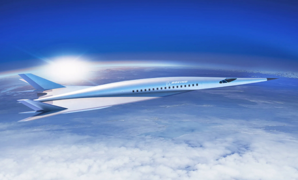
Boeing hypersonic airliner concept, from Wired, "Boeing’s Proposed Hypersonic Plane Is Really, Really Fast" by Eric Adams, published June 28, 2018. https://www.wired.com/story/boeing-hypersonic-mach-5-jet-concept/
Design Structure Matrix Allocation
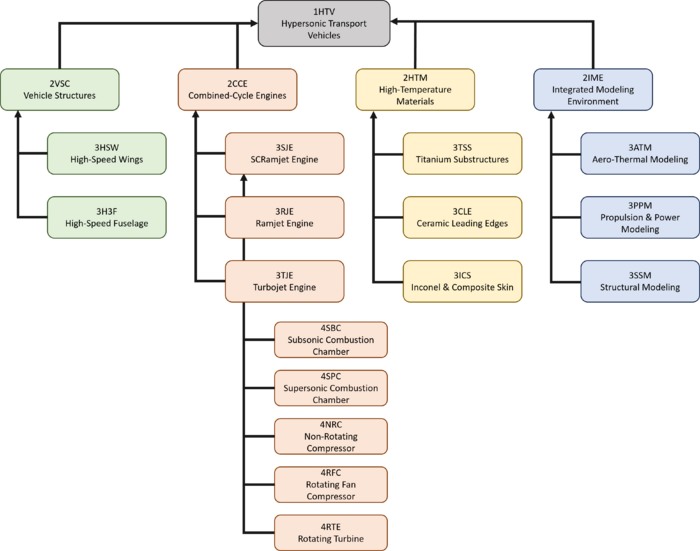
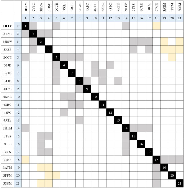
A hierarchical breakdown of a subset of the technologies required to enable the development of hypersonic transport vehicles is shown below. Note that the level 1 hypersonic transport vehicle technology is decomposed into four level two sub-technologies: vehicle structures, combined-cycle engines, high-temperature materials, and integrated modeling environments.
It is noted that several interactions exist between the various sub-technologies shown below. Such interactions are indicated in the design structure matrix (DSM), shown below. Interactions shown in grey represent either physical or component-type linkages (i.e. high-speed wings are part of hypersonic transport vehicles), whereas interactions in yellow represent information flows (i.e. aero-thermal analysis models are required for the development of high-speed wings).
Roadmap Model Using Object-Process Methodology (OPM)
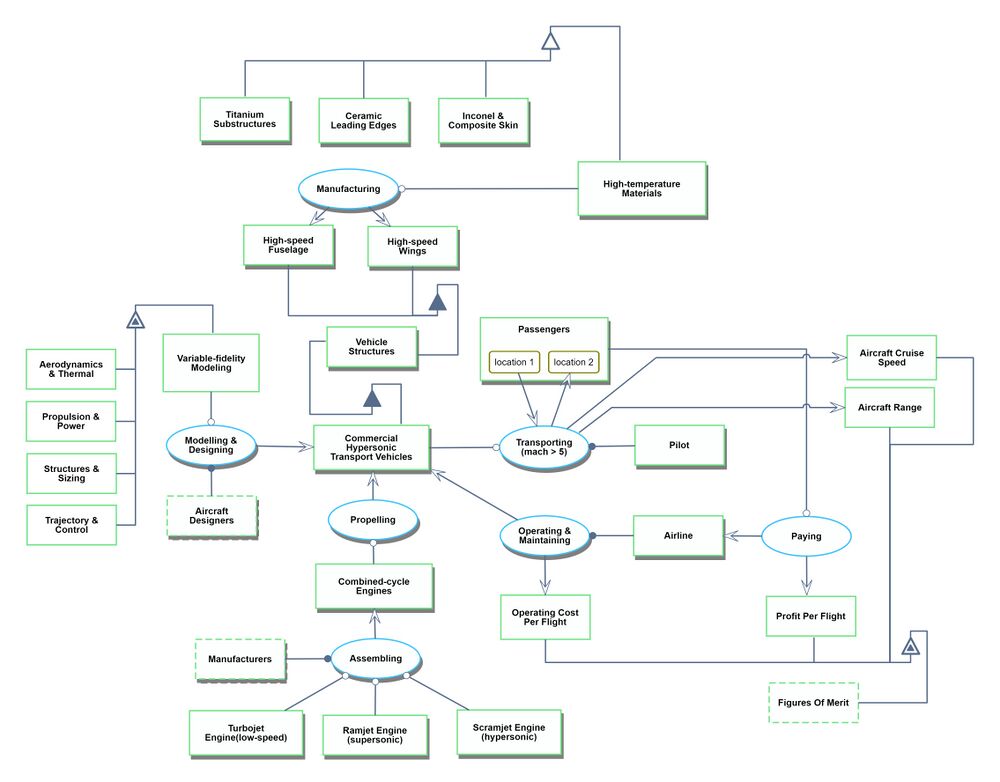
An OPM diagram showing a sample of the processes required for the creation and operation of commercial hypersonic transport vehicles is shown below. Note that the technology of interest (hypersonic transport vehicle) is shown near the center of the figures. The hypersonic transport vehicle serves to transport passengers from one location to another (also indicated near the center of the diagram). FOMs are shown towards the bottom right, with connections to relevant processes. It is noted that the sub-technologies shown in the diagram (high-temperature materials and structures, variable fidelity modeling, and combined-cycle engines) are discussed in detail by Bowcutt in [3].
Figures of Merit
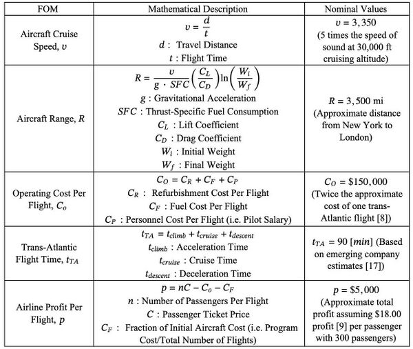
The figures of merit (FOMs) relevant to commercial hypersonic transports include the distance covered per time (speed, v), aircraft range R, operating cost per flight C_O, the aircraft profit per flight p, the number of flights per aircraft, and the trans-Atlantic flight time. The profit p generated by the airline may be the single most important figure of merit, as it is the ultimate driver for the existence of commercial hypersonic vehicles (without profit, airlines will not offer such a service). These FOMs are described in the table below.
| Figure of Merit (FOM) | Unit | Description |
|---|---|---|
| Aircraft Speed | [m/s] | Maximum velocity of the aircraft during the flight. Correlates to cruise velocity for hypersonic commercial transport vehicles. |
| Aircraft Range | [m] | Maximum distance traveled per flight at maximum payload capacity. |
| Operating Cost | [$] | Cost per flight to operate the aircraft. Function of the personnel (pilot and crew) cost, fuel cost and post-flight refurbishment required prior to future flights. |
| Profit per Flight | [$] | Function of the number of passengers, price per ticket, operating cost and overall programmatic cost. |
| Flights per Aircraft | [n] | Number of flights will be limited by structural fatigue due to system cycles. |
| Trans-Atlantic Flight Time | [hrs] | A function of aircraft velocity that captures the transitions between takeoff, cruise, and landing phases of flight. Because of the length of the transient phases (takeoff and landing), this FOM more directly correlates to the benefit to the consumer than the aircraft velocity FOM. |
The FOMs above are described mathematically, including expected nominal values in the table below.
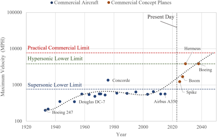
It is possible to review historic trends of the FOMs by plotting the FOM value of a given system over time. In the figure below, we plot the maximum velocity of various existent commercial aircraft and projected commercial aircraft concepts.
The practical maximum flight speed for commercial aircraft is indicated at Mach 10, or approximately 7,700 mph. This limit exists because the time savings of supersonic and hypersonic flight become very limited at very high Mach numbers, as the vehicle spends the vast majority of a given flight accelerating and subsequently decelerating from its intended cruise speed. Reviewing the figure above, we argue that hypersonic commercial transport systems are in the incubation stage of their lifecycle. At present, no such vehicles exist, but the various research demonstrations show that we are approaching a point where hypersonic commercial transit can become a reality. Further, we are likely at the stagnation point of progress on traditional subsonic commercial vehicles. As such, for customers with enough capital to afford higher speed travel, hypersonic transport vehicles will likely eventually disrupt the commercial aviation market. If the timeline projected by the various concept vehicles is to be trusted, this disruption should occur in the early 2030s.
It is important to note that achieving higher speed flight is driven by underlying technology advances and differences in aircraft design. These differences are visible in the image below, which shows example transonic, supersonic, and hypersonic aircraft. Clearly, the higher speed vehicles are becoming more slender, and the degree of coupling of the subcomponents (i.e. the wings, fuselage, and propulsion devices) is becoming much higher.
Alignment with Company Strategic Drivers
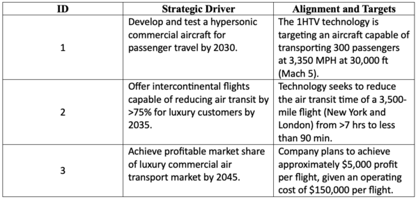
The figure below shows the alignment between 1HTV technology FOM targets and the company strategic drivers. This figure also provides an approximate timeline for implementation of company strategy.
Positioning of Company vs Competition
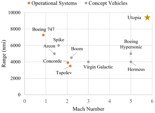
The figure below provides an overview of the range and cruise velocity performance of historical and current competitors in the market in the commercial air transportation market. In general, range and velocity are inversely related. However, it is difficult to draw a realistic Pareto frontier because of the technical immaturity of competing concepts in the market. Operational systems are shown in orange on the figure below but all represent subsonic or supersonic transport systems. The hypersonic systems shown in grey are all notional systems that have not published design specifications and have not demonstrated mature propulsion or thermal protection technologies to support their projected performance. In general, the company will drive towards the utopia point maximizing both range and velocity. Velocity, in this case is a useful proxy for total flight time.
Technical Model
Morphological Matrix
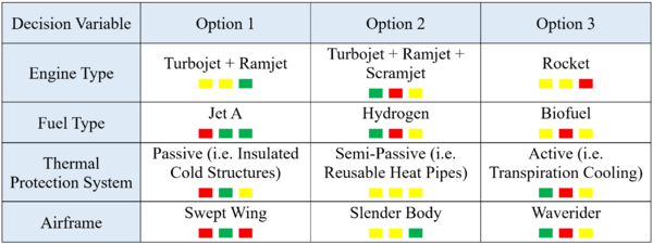
There are a myriad of architectural decisions that must be considered when designing a hypersonic transport system, of which it is impossible to list them all. In the below architectural matrix, we list four of the most important decision areas. For each area, we list three possible solution options. These options are loosely quantified according to the relative performance impact (i.e. velocity and aircraft range), cost, and effect on system safety. For example, a color code of green-red-yellow indicates relatively high performance impact, high cost, and average or undetermined impact on system safety.
These tradeoffs listed above are indicated on a commercial hypersonic aircraft concept from Hermeus in the image below [20].
FOM Sensitivities
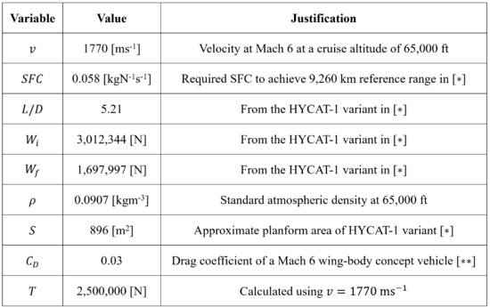
Technical models are developed for the FOMs of aircraft range and aircraft velocity in the subsections below. Calculation of the dimensional and normalized sensitivity values is performed using the baseline values shown in the table below.
∗M. Robert and D. Brewster, “Hypersonic cruise aircraft propulsion integration study, volume 2,” Sep. 1979, https://ntrs.nasa.gov/citations/19800006816.
∗∗Dillon, J. L. and Pittman, J. L., “Aerodynamic Characteristics at Mach 6 of a Wing-Body Concept for a Hypersonic Research Airplane,” NASA Technical Paper 1249, Aug. 1978, https://ntrs.nasa.gov/api/citations/19780022112/downloads/19780022112.pdf.
Aircraft Range
As with propeller and jet powered aircraft, the range of a hypersonic aircraft is calculated using the Breguet range equation from the aircraft velocity v, specific fuel consumption of the engine SFC, lift-to-drag ratio L/D and the ratio of the initial to final weight of the vehicle Wi/Wf. The difference between the initial and final weight of the aircraft is equal to the weight of fuel consumed. The Breguet range equation is the following:
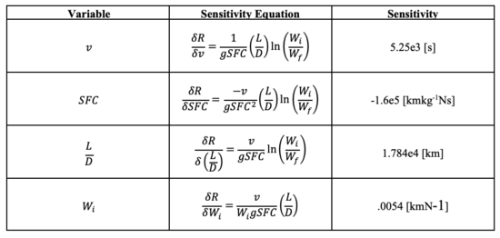
Using baseline values for the variables of the Breguet range equation, we can calculate numerical values for the sensitivity of range to a subset of variables. Note, this simplification of the range equation does not include the variation in v, SFC and L/D during the climb and descent phases.
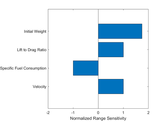
A tornado diagram showing the normalized range sensitivity values is provided below.
The diagram shows that range is most sensitive to initial weight, and therefore propellant weight. Range is equally sensitive to SFC, velocity and L/D. The range of the hypersonic aircraft considered is 2 orders of magnitude more sensitive to velocity than the “traditional” subsonic turbojet considered in class and is 3 times more sensitive to SFC. This increased sensitivity highlights the challenges in mission, vehicle and engine design for hypersonic commercial transport.
Aircraft Velocity
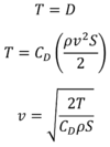
For this FOM, we develop a technical model based on the assumption that during cruise the aircraft is in steady flight, meaning that thrust T exactly equals the drag D. We then express drag in terms of the drag coefficient and solve for velocity as follows:
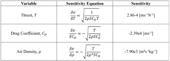
As such, we have expressed the velocity as a function of thrust, drag coefficient, flow density, and reference area. Ignoring the reference area, the velocity sensitivity to vehicle thrust, drag coefficient, and air density is expressed by taking the derivative with respect to each variable. The below table provides the resultant sensitivity equations along with the dimensional sensitivity result.
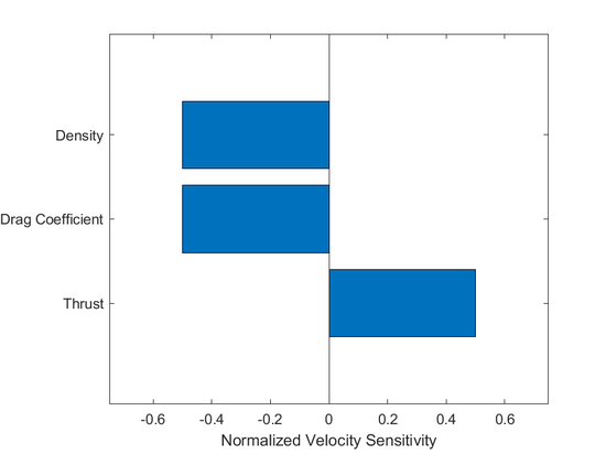
A tornado diagram showing the normalized range sensitivity values is provided below.
Reviewing the chart, the normalized sensitivity of velocity is equal in magnitude across the three variables considered. This is because all values in the original velocity equation are effectively interchangeable, in that the variables are simply multiplied together with some overarching operation to determine the cruise velocity. As such, velocity is equally sensitive to changes in any given value.
Key Publications and Patents
Various publications and patents relevant to hypersonic transport vehicles are discussed in the subsections below.
Publications
The paper search was performed using Google Scholar to identify relevant publications relating to hypersonic transport technologies and multidisciplinary hypersonic design optimization. From there, papers were sorted based on the number of citations to roughly quantify by impact. Two of the interesting, impactful papers are discussed below.
| Title | Year | Author | Organization | Source |
|---|---|---|---|---|
| Hypersonic Transport Technology | 1977 | Kirkham, F. S. and Hunt, J. L. | NASA Langley | Acta Astronautica, Vol. 4 |
| Advancements in Multidisciplinary Design Optimization Applied to Hypersonic Vehicles to Achieve Performance Closure |
2012 | Bowcutt, K., et al. | Boeing Phantom Works | 15th AIAA International Space Planes and Hypersonic Systems and Technology Conference |
1. Kirkham and Hunt’s paper on hypersonic transport technology is a very early exploration of the feasibility of developing a commercial hypersonic airliner. The study notes that a 200 passenger Mach 6 aircraft would likely have a takeoff weight that is not prohibitively large. The work lays out the need for more advanced propulsion systems and discusses required advances in vehicle cooling and structures before hypersonic transports can become a reality. Interestingly, the article (written in 1977) notes that commercial hypersonic vehicles may become a reality in the early 2000s. Clearly, this has not yet come to fruition, likely as a consequence of reduced interest after the failure of various hypersonic single stage to orbit (SSO) concept studies and because of considerable difficulty in making the concept economically viable given the state of current technology.
2. Bowcutt, et al.’s paper on hypersonic multidisciplinary design optimization discusses the need for high-fidelity models and optimization frameworks for developing hypersonic aircraft. In general, hypersonic systems involve tight coupling of the components (i.e. structures, propulsion, thermal protection, etc.) and as such these systems must be designed using integrated design frameworks. The paper specifically mentions the need for geometry generation tools linked to disciplinary analysis models that allow for the rapid generation and analysis of hypersonic vehicle designs. Several such tools now exist and are actively used to design hypersonic vehicles today. Such tools will likely be used to design future commercial hypersonic transport systems with reasonable physical and economic performance.
Patents
The search for relevant patents was initially conducted via a search for keywords such as “hypersonic” and “scramjet” using the US Patent and Trademark Office Patent Public Search tool. This revealed hundreds of records, many of which were only loosely related to technology needed for commercial hypersonic transport vehicles. To focus on more relevant technologies, an additional search was conducted on Google Patents using keywords such as “hypersonic transport vehicles” and “combined cycle scramjet engines”. This revealed a much smaller set of patents with more direct ties to hypersonic transport vehicles. Three of particular interest are discussed and noted in the table below.
| Patent Number | CPC | Title | Year Filed | Assignee |
|---|---|---|---|---|
| US 20030182928 A1 | F02K7/14 | Scram Jet Engine Design | 2002 | Aerojet Rocketdyne |
| US 20120159925 A1 | F02k7/16 | Turbine Based Combined Cycle Engine | 2010 | Rolls Royce |
| US 20150108269 A1 | B64C30/00 | Hypersonic Aircraft | 2013 | Hypermach Aerospace Industries |
1. Patent number US 20030182928 A1 on scramjet engine design discusses the invention of a supersonic combustion engine for a hypersonic vehicle. The invention is a specific instance of a scramjet engine comprised of outer and inner walls that define a flowpath, as well as a network of internal heat exchangers and cooling passages used to cool the vehicle when flying at hypersonic speeds. The internal piping allows fuel to serve as coolant, thereby reducing the thermal strain experienced by the engine structure. The engine is similar to the one used on the X-51 waverider experimental aircraft that flew in 2013. The patent is relevant to hypersonic transport vehicles as it represents a step forward to developing low-cost, low-weight engines that can be used to power hypersonic vehicles. Selected images from the patent are shown in Fig. 2, below. A diagram of the patented engine is shown on the right, with its location within a hypersonic vehicle shown on the left.
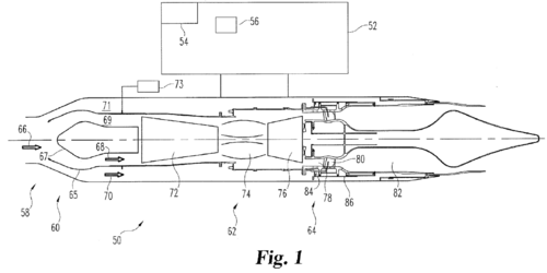
2. Patent number US 20120159925 A1 on a turbine based combined cycle engine discusses the invention of a high-speed aircraft engine that can operate in multiple modes and at a range of Mach numbers, including in a supersonic ramjet mode or in a subsonic turbine mode. The invention includes a bypass valve that can limit airflow into the gas turbine engine when operating at high speeds. In this mode, some compression is generated by shock waves located in the engine inlet, with no need for the air to pass through a rotating compressor. In addition, the patent claims the cylindrical structure used to house the engine, as well as the method used to capture and combust airflow within the engine. A diagram of the invention pulled from the patent document is shown in Fig. 3, below. Such an invention can be considered foundational work for the development of combined-cycle subsonic, supersonic, and hypersonic engines that will eventually power commercial hypersonic transport vehicles.
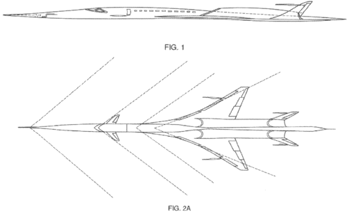
3. Patent number US 20150108269A1 on hypersonic aircraft covers the invention of a Mach 4.0 and up airliner for carrying passengers over long distances. The aircraft has a unique low-profile design intended to maximize aerodynamic performance. The patent covers the location and integration of two engines positioned above the wings that help to stabilize the structure and reduce wave drag. The engines are attached to the vehicle by a composite titanium structure that passes through the wing box. Several other geometry considerations that dictate the vehicle’s aerodynamic performance are also noted in the patent. Such work is a clear step towards future hypersonic commercial transit. Diagrams showing the patented technology are shown in Fig. 4, below. It is noted that the vehicles which will eventually transport people and cargo across oceans at hypersonic speeds will likely look very different than this one. However, such vehicles will likely include aerodynamic designs that are similar to, or match those discussed in the mentioned patent.
Having now reviewed several of the patents related to technologies important for hypersonic commercial transport vehicles, it is interesting to note that the patented inventions show a clear story of technology improvement over time. Early patented hypersonic vehicle designs, for instance, tended to show vehicles that were manually designed (without the use of modern computational tools) and as such had generally poor aerodynamic characteristics. Newer patented designs show clearly superior vehicles designs that involve tighter integration of the individual components and show more effective aerodynamic characteristics.
Financial Model
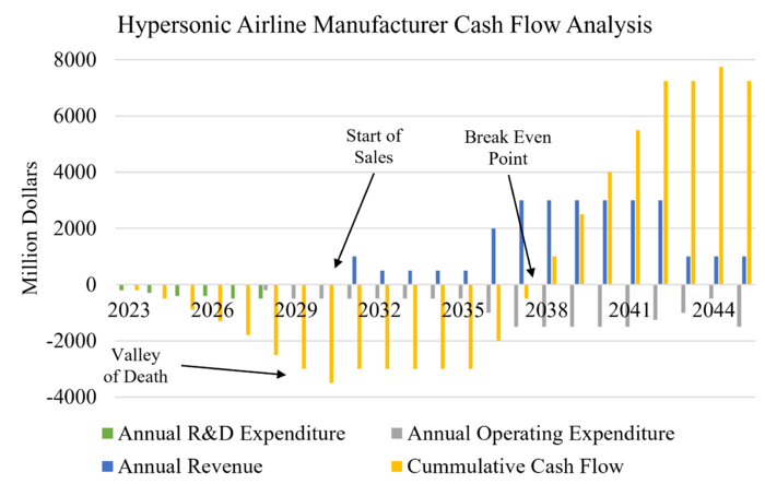
Current hypersonic airline manufacturers must invest in the previously mentioned research and development projects so that they can begin constructing (and selling) hypersonic aircraft. As such, manufacturers will initially accept a negative cash flow such that they may achieve a net positive income in the long term. The below figure provides a projection of what we may expect to see from a hypersonic transport vehicle manufacturing company's finances over the next two decades.
Model Source and Assumptions
The above financial model is based on Deloitte's "ROSETTA" cash flow projection model for a Mach 5, 100 passenger, 5,000 nmi passenger jet. The model accounts for markets reached by the described vehicle, as well as projected changes to fuel prices and air travel demand over the coming decades. The model does not not account for research and development costs before manufacturing. As such, in the above figure, we have added out own research and development expenditures. These costs scale from $200M to $500M over a period of five years. Such values are projected based on the expected cost of various critical sub-technologies, such as the development of combined-cycle engines and more effective thermal protection systems.
Notably, the model assumed an approximate certification date in 2030. Challenges with aircraft certification are not addressed by the FOMs or technical model presented in this roadmap. Any current and future hypersonic transport vehicle manufacturers must account for this process when developing financial forecasts and timelines to deliver a product to the market.
Model Source: "Commercial Hypersonic Transportation Market Study," Deloitte, April 2021, https://ntrs.nasa.gov/api/citations/20210014711/downloads/Deloitte%20Consulting%20LLP%20-%20Commercial%20Hypersonic%20Transportation%20Market%20Study%20-%20April%202021.pdf.
List of Notable Hypersonic Demonstrator Vehicles
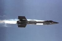
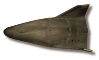
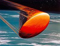
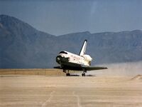
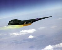
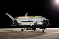
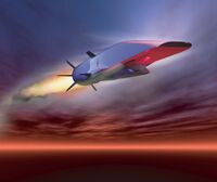
As has been noted previously, there is a plethora of sub-technologies that are required to enable the development and practical application of commercial hypersonic transport vehicles (or more broadly, hypersonic vehicles in general). Indeed, there have been innumerable projects that have demonstrated the use of various types of high-performance materials, high-energy density fuels, hypersonic air-breathing engines, and many other subsystem-level technologies. As such, in this section we focus the below list of demonstrator projects on vehicle-level programs. Further, to make the list manageable we focus on exclusively American hypersonic vehicle projects (with the notable exception of the German V-2 rocket). We do not claim that the list is exhaustive of all hypersonic vehicle technology demonstrator projects, but that it merely gives a sense of the notable milestones achieved in hypersonic flight from the 1940s and onward.
| Image | Project | Year | Milestone | Type | Budget (2023 USD) |
|---|---|---|---|---|---|
| V-2 Rocket | 1949 | First object of human origin to achieve hypersonic flight | Ballistic rocket | 8,744M | |
| X-17 | 1957 | Tests of high-Mach atmospheric entry | Vehicle | Unknown | |
| X-15 | 1959 | Piloted Mach 6+ flight Flight at 100,000+ ft altitude |
Aircraft | 2,515M | |
| X-23A | 1966 | First maneuverable hypersonic reentry vehicle | Reentry Vehicle | Unknown | |
| Apollo Entry Capsule | 1966 | Piloted hypersonic reentry | Teentry Vehicle | 179B | |
| Space Shuttle | 1981 | Piloted, maneuverable, & reusable hypersonic reentry | Reentry vehicle | 268B | |
| X-43 | 2001 | First thrust-producing scramjet powered vehicle | Aircraft | 375M | |
| X-37 | 2006 | Reusable hypersonic reentry vehicle | Reentry Vehicle | 293M | |
| X-51 | 2010 | 200+ second scramjet-powered hypersonic flight | Aircraft | 335M |
Technology Strategy Statement
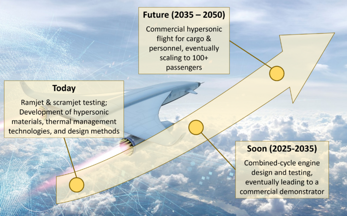
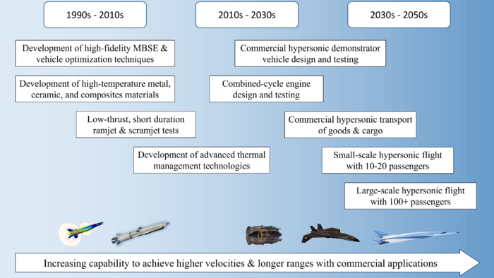
Our target is to develop a commercial aircraft capable of transporting people and cargo at hypersonic speeds. Before this can be achieved, advances in underlying technologies such as improved high-temperature materials, thermal management systems, integrated design methodologies, and combined-cycle engines must occur. A subset of the various milestones that are occurring today, and will occur in the future en route to practical commercial hypersonic travel is presented in the high-level "swoosh" chart below. This chart is further broken down into the more detailed timeline shown below, with example images of the various technologies under development shown near the bottom.
References
[1] Hayward, J. and Ahlgren, L., “The Cost of Flying: What Airlines have to Pay to get you in the Air,” Simple Flying, 26 May 2023, https://simpleflying.com/the-cost-of-flying/.
[2] Gray, S., “Here’s how much Airlines are Profiting off your Plane Ride,” Money, 14 Feb. 2018, https://money.com/airline-profit-per-passenger/#:~:text=According%20to%20the%20Wall%20Street,airlines%20was%209%25%20in%202017.
[3] Bowcutt, K. G., “Flying at the Edge of Space and Beyond: The Opportunities and Challenges of Hypersonic Flight,” National Academy of Engineering, 25 June 2020, https://www.nae.edu/234431/Flying-at-the-Edge-of-Space-and-Beyond-The-Opportunities-and-Challenges-of-Hypersonic-Flight#:~:text=decades%20to%20come.-,Flying%20at%20the%20Edge%20of%20Space%20and%20Beyond%3A%20The,and%20Challenges%20of%20Hypersonic%20Flight&text=The%20primary%20benefit%20of%20hypersonic,hours%2C%20or%20achieve%20Earth%20orbit.
[4] Rodrigue, J.-P. (2020). The geography of transport systems (Fifth edition). Routledge Taylor
& Francis Group.
[5] “Boeing Model 247.” Http://Www.aviation-History.com/Boeing/247.Html, The Aviation
History On-Line Museum, 17 Apr. 2022, www.aviation-history.com/boeing/247.html.
Accessed 4 Oct. 2023.
[6] “Celebrating Concorde | Information | British Airways.” Britishairways.com, 2023,
www.britishairways.com/content/en/de/information/about-ba/history-and- heritage/celebrating-concorde. Accessed 4 Oct. 2023.
[7] “Railway Speed Record.” Wikipedia, 28 Sept. 2023,
en.wikipedia.org/wiki/Railway_speed_record. Accessed 5 Oct. 2023.
[8] Hayward, J. and Ahlgren, L., “The Cost of Flying: What Airlines have to Pay to get you in the Air,” Simple Flying, 26 May 2023, https://simpleflying.com/the-cost-of-flying/.
[9] Gray, S., “Here’s how much Airlines are Profiting off your Plane Ride,” Money, 14 Feb. 2018, https://money.com/airline-profit-per-passenger/#:~:text=According%20to%20the%20Wall%20Street,airlines%20was%209%25%20in%202017.
[10] Bowcutt, K. G., “Flying at the Edge of Space and Beyond: The Opportunities and Challenges of Hypersonic Flight,” National Academy of Engineering, 25 June 2020, https://www.nae.edu/234431/Flying-at-the-Edge-of-Space-and-Beyond-The-Opportunities-and-Challenges-of-Hypersonic-Flight#:~:text=decades%20to%20come.-,Flying%20at%20the%20Edge%20of%20Space%20and%20Beyond%3A%20The,and%20Challenges%20of%20Hypersonic%20Flight&text=The%20primary%20benefit%20of%20hypersonic,hours%2C%20or%20achieve%20Earth%20orbit.
[11] Rodrigue, J.-P. (2020). The geography of transport systems (Fifth edition). Routledge Taylor
& Francis Group.
[12] “Boeing Model 247.” Http://Www.aviation-History.com/Boeing/247.Html, The Aviation
History On-Line Museum, 17 Apr. 2022, www.aviation-history.com/boeing/247.html.
Accessed 4 Oct. 2023.
[13] “Celebrating Concorde | Information | British Airways.” Britishairways.com, 2023,
www.britishairways.com/content/en/de/information/about-ba/history-and- heritage/celebrating-concorde. Accessed 4 Oct. 2023.
[14] “Railway Speed Record.” Wikipedia, 28 Sept. 2023,
en.wikipedia.org/wiki/Railway_speed_record. Accessed 5 Oct. 2023.
[15] Independent Market Study for Commercial Hypersonic Transportation. Deloitte Consulting, Apr. 2021.
[16] Robert M. and Brewster, D., “Hypersonic cruise aircraft propulsion integration study, volume 2,” Sep. 1979. [Online]. Available: https://ntrs.nasa.gov/citations/19800006816
[17] Dillon, J. L. and Pittman, J. L., “Aerodynamic Characteristics at Mach 6 of a Wing-Body Concept for a Hypersonic Research Airplane,” NASA Technical Paper 1249, Aug. 1978, https://ntrs.nasa.gov/api/citations/19780022112/downloads/19780022112.pdf.
[18] Swoosh Background Image, from The Telegraph, "Hypersonic Planes a Step Closer After Breakthrough that Prevents Engine Melting at 4,000 mph," by Ellie Zolfagharifard, Published 22 Oct. 2019, https://www.telegraph.co.uk/technology/2019/10/22/hypersonic-planes-step-closer-breakthrough-prevents-engine-melting/
[19] Boeing hypersonic airliner concept, from Wired, "Boeing’s Proposed Hypersonic Plane Is Really, Really Fast," by Eric Adams, Published 28 June 2018, https://www.wired.com/story/boeing-hypersonic-mach-5-jet-concept/
[20] Hermeus Halcyon, from The Drive, "Air Force Throws Millions at Startup Trying to Build Reusable Hypersonic Aircraft," by Thomas Newdick, Published 5 Aug. 2021, https://www.thedrive.com/the-war-zone/41848/air-force-throws-millions-at-startup-trying-to-build-reusable-hypersonic-aircraft
[21] Engine Concept, from Aviation Week, "Rotating Detonation Engines Are Emerging Priority for U.S. Air Force," by Guy Norris, Published 9 Sept. 2020, https://aviationweek.com/defense-space/aircraft-propulsion/rotating-detonation-engines-are-emerging-priority-us-air-force?check_logged_in=1
[22] X-51 Image, from Modern Warships, "X-51 Waverider," https://modern-warships.fandom.com/wiki/X-51_Waverider
[23] Schaufele, R. D., "The Required Technology Combinations for High-Speed Commercial Aircraft," Douglas Aircraft Company Report, https://onlinepubs.trb.org/Onlinepubs/trcircular/333/333-003.pdf

![Image credit [20]](/images/thumb/3/38/HyperVehicle_MorphMatrix.png/700px-HyperVehicle_MorphMatrix.png)
