Difference between revisions of "Bioelectronic Devices for Electrical Stimulation"
| (4 intermediate revisions by one other user not shown) | |||
| Line 1: | Line 1: | ||
Roadmap Creators: [https://www.linkedin.com/in/jorge-farfan-19261a12a/ | Jorge Farfan Perdomo] [https://www.linkedin.com/in/neenarajan/ | Neena Rajan] [https://www.linkedin.com/in/daniel-reveron-ab1a97106/ | Daniel Reveron] | |||
Time Stamp: 5 December 2023 | |||
=Technology Roadmap Sections and Deliverables= | =Technology Roadmap Sections and Deliverables= | ||
The Bioelectronic Devices for Electrical Stimulation ['''3BDES'''] is a level 3 technology roadmap focused around electrically stimulating biological systems (e.g., muscles, nerves, cells) for clinical purposes. A roadmap will be developed to explore the current status of the technology and the potential venues of progress from both a technical and business side. | The Bioelectronic Devices for Electrical Stimulation ['''3BDES'''] is a level 3 technology roadmap focused around electrically stimulating biological systems (e.g., muscles, nerves, cells) for clinical purposes. A roadmap will be developed to explore the current status of the technology and the potential venues of progress from both a technical and business side. | ||
| Line 164: | Line 168: | ||
[[File:3BDES Normalization.png]] | [[File:3BDES Normalization.png]] | ||
[[File:3BDES Tornado Chart.png]] | [[File:3BDES Tornado Chart Updated.png]] | ||
From the previous variables, the only feasible alternative to extend the life of the battery would be to increase the power density of the battery by improving the current Li/SVO-CFX technology or changing the battery to a new composition with better characteristics. All the other options are not feasible since they impact the weight, size, and aspects of the stimulation therapy and are not negotiable. | From the previous variables, the only feasible alternative to extend the life of the battery would be to increase the power density of the battery by improving the current Li/SVO-CFX technology or changing the battery to a new composition with better characteristics. All the other options are not feasible since they impact the weight, size, and aspects of the stimulation therapy and are not negotiable. | ||
| Line 247: | Line 251: | ||
[[File:3BDES PatentImage1.png]] | [[File:3BDES PatentImage1.png]] | ||
Patent "US 3057356 A" is the first documented patent in history that described the most widely used bioelectronic stimulator, the cardiac pacemaker (CP). Wilson Greatbatch, who is also the author of the patent, designed the CP. The patent was filed the same year Dr. William Chardack and Wilson Greatback implanted the pacemaker in a 77-year-old man and worked [ | Patent "US 3057356 A" is the first documented patent in history that described the most widely used bioelectronic stimulator, the cardiac pacemaker (CP). Wilson Greatbatch, who is also the author of the patent, designed the CP. The patent was filed the same year Dr. William Chardack and Wilson Greatback implanted the pacemaker in a 77-year-old man and worked [22]. The pacemaker was possible for the advancement in the electronics industry that led to the discovery of the transistor (Patent US 2569347 A) in 1948 and introduced commercially in 1954 [23]. Before that, the word stimulator was vaguely used in patents such as US 2410499 (Stimulator) A and US 2609499 A (Muscle Stimulator). However, Greatbach's patent described the main components of the pacemaker as we know it today. | ||
In the patent, Greatbach discusses the uses of the stimulator in medicine and considers the pacemaker technology as a potential substitute for a diseased or non-functional organ within the human body capable of performing physiological functions. | In the patent, Greatbach discusses the uses of the stimulator in medicine and considers the pacemaker technology as a potential substitute for a diseased or non-functional organ within the human body capable of performing physiological functions. | ||
| Line 293: | Line 297: | ||
[[File:3BDES PatentImage3.png]] | [[File:3BDES PatentImage3.png]] | ||
Patent US-5614331-A "describes a method of using a medium-rate CFx cell to power the circuitry of an implantable defibrillator while simultaneously using a SVO cell to provide the power supply under high-rate applications for the device. The advantage of this method is that all the high-power SVO energy is reserved for high-power applications such as charging a capacitor while the device monitoring function, for example, for monitoring the heartbeat, which requires low power requirements, is provided by the high capacity CF.sub.x system" [ | Patent US-5614331-A "describes a method of using a medium-rate CFx cell to power the circuitry of an implantable defibrillator while simultaneously using a SVO cell to provide the power supply under high-rate applications for the device. The advantage of this method is that all the high-power SVO energy is reserved for high-power applications such as charging a capacitor while the device monitoring function, for example, for monitoring the heartbeat, which requires low power requirements, is provided by the high capacity CF.sub.x system" [24] | ||
This patent is of importance to us since it is the first patent that mentions that mixing high-capacity materials (CFx) with high-rate cathode materials (SVO) produces batteries suitable for biomedical stimulators. | This patent is of importance to us since it is the first patent that mentions that mixing high-capacity materials (CFx) with high-rate cathode materials (SVO) produces batteries suitable for biomedical stimulators. | ||
| Line 300: | Line 304: | ||
The previous reasons explain why current medical devices and companies such as Abbott and Medtronic use these batteries: their high energy density and capacity within a small device. The battery can perform two stimulation modes while having a long battery life. | The previous reasons explain why current medical devices and companies such as Abbott and Medtronic use these batteries: their high energy density and capacity within a small device. The battery can perform two stimulation modes while having a long battery life. | ||
==Technology Strategy Statement== | ==Technology Strategy Statement== | ||
| Line 362: | Line 365: | ||
'''Section 1.8''' | '''Section 1.8''' | ||
[ | [21] de Weck, O. L. (2023). Technology Valuation and Finance [Lecture 17 slide]. 16.887 | ||
------ | ------ | ||
| Line 368: | Line 371: | ||
'''Section 1.10.2''' | '''Section 1.10.2''' | ||
[ | [22] "The invention of the cardiac pacemaker", U.S. Department of Veterans Affairs (2023, October 29) .Retrieved from: https://www.research.va.gov/research_in_action/The-invention-of-the-cardiac-pacemaker.cfm | ||
[ | [23] "First Commercial Transistor", BBC. (2023, October 29). Retrieved from: https://www.bbc.co.uk/ahistoryoftheworld/objects/LIDD7lI4QumcPPyZenkdRQ | ||
[ | [24] "Double Current Collector Cathode Design Using Mixtures Of Two Active Materials For Alkali Metal Or Ion Electrochemical Cells", Gan and Tekeuchi (Feb 17, 2004). Retrieved from: https://image-ppubs.uspto.gov/dirsearch-public/print/downloadPdf/6692865 | ||
Latest revision as of 14:49, 5 December 2023
Roadmap Creators: | Jorge Farfan Perdomo | Neena Rajan | Daniel Reveron
Time Stamp: 5 December 2023
Technology Roadmap Sections and Deliverables
The Bioelectronic Devices for Electrical Stimulation [3BDES] is a level 3 technology roadmap focused around electrically stimulating biological systems (e.g., muscles, nerves, cells) for clinical purposes. A roadmap will be developed to explore the current status of the technology and the potential venues of progress from both a technical and business side.
Roadmap Overview
Bioelectronic Medicine is a novel approach that combines molecular medicine, neuroscience, and bioengineering to threaten and diagnose diseases and injuries. Bioelectronic devices can read and modulate electrical activity within the body. These devices open new possibilities and alternatives to diagnose and treat real-time diseases by using electrical pulses to restore health instead of chemical and biological drugs. In the literature, Bioelectronic Medicine can be found as neuromodulation, biostimulation, or electroceuticals. [1] [2] [3]
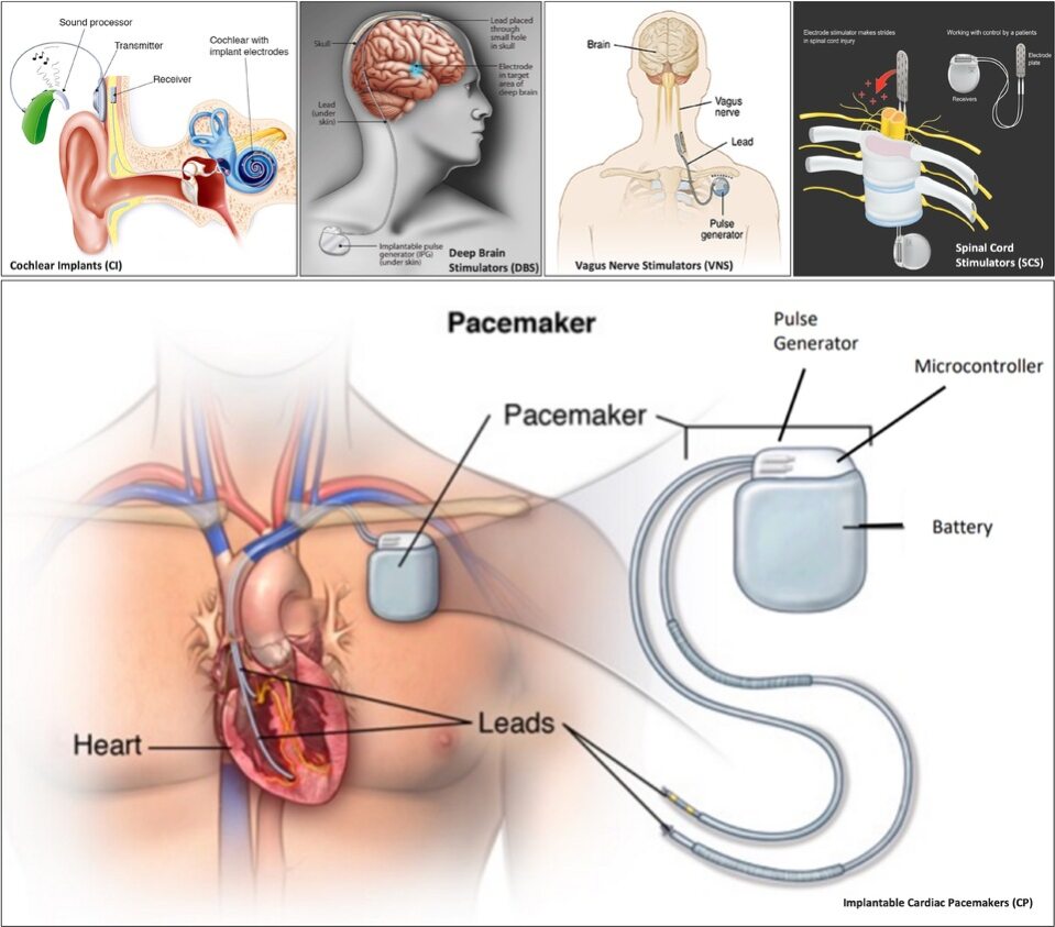
The bioelectronic devices that delivers electrical stimulation and dominate the market are:
- Implantable Cardioverter Defibrillators (ICD)
- Cardiac Pacemakers (CP)
- Cochlear Implants (CI)
- Spinal Cord Stimulators (SCS)
- Deep Brain Stimulators (DBS)
- Sacral Nerve Stimulators (SNS)
- Transcutaneous Electrical Nerve Stimulators (TENS)
- Vagus Nerve Stimulators
Below are example electrical stimulators for some specific use cases listed above: [4] [5] [6] [7] [8]
For this roadmap, we're focusing on the core technology that is electrical stimulators, which would support a wide range of use cases through modularity. Potentially, the resulting technology would form a link in the value chain of existing products (e.g. enhancing components within the pacemakers); this is not the only strategy available, as a strong architecture and vertical integration could truly develop the ability for this technology to be slightly modified to stimulate different parts of the body.
Most of our referenced technologies in the sections include cardiac pacemakers and cardiac defibrillators, as combined they share roughly half the market, and extensive data is available for reference.
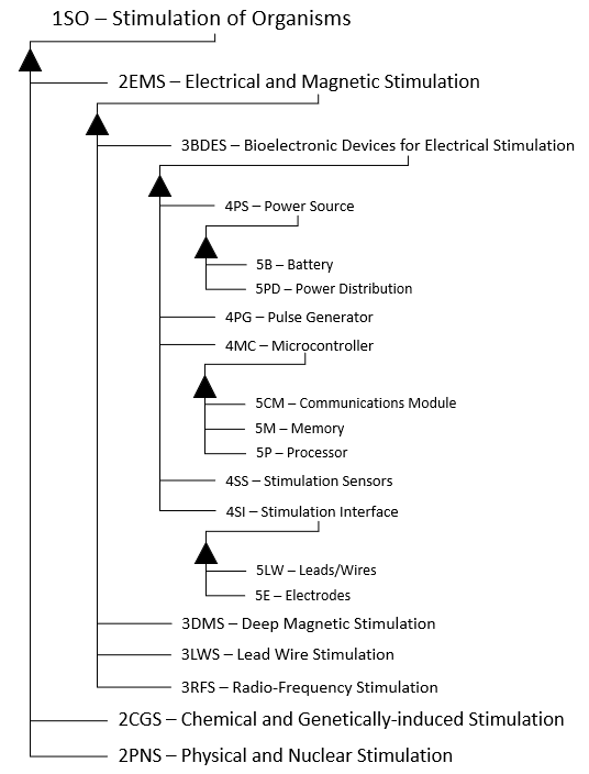
Design Structure Matrix (DSM) Allocation
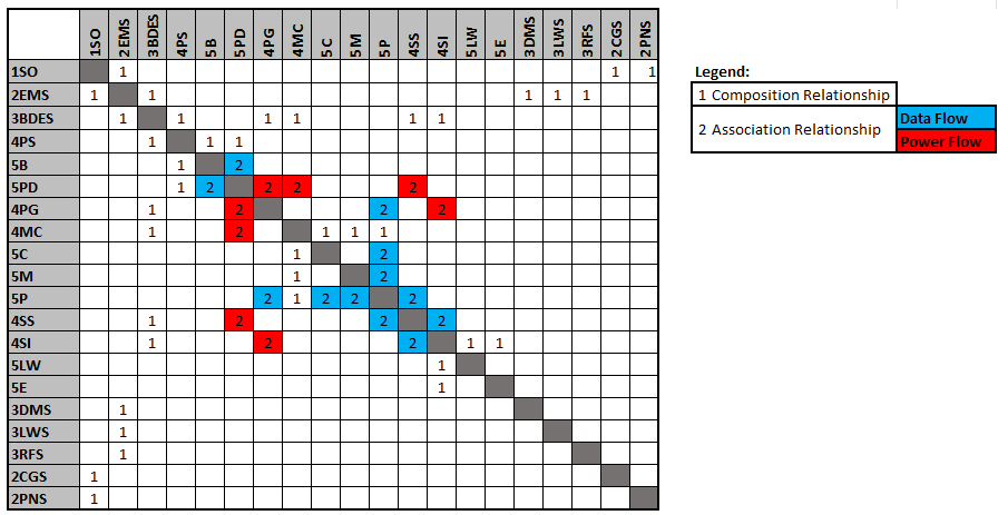
The above breakdown of the technology shows different potential roadmaps of consideration within the wider Organism Stimulation level 1 roadmap. Since the technology that was selected is generic in nature (i.e. no particular target organism for stimulation), alternative venues of implementation such as chemical stimulation can be compared in the future as their own roadmaps. Composition relationships, defined by "1", establish parent-child relationships among elements. The enabling technologies are listed under the roadmap of interest (3BDES): Power Source (4PS: to power the electronic components), Pulse Generator (4PG: to emit the electric signals), Microcontroller (4MC: to receive, analyze, control the pulse generator, and communicate with an external device), Stimulation Sensors (4SS: to sense feedback signals from the target organism), and Stimulation Interfaces (4SI: to interface directly with the organism). The level 4 and 5 technologies within the 3BDES roadmap are interrelated by power flows and data flows as shown.
Roadmap Model using OPM
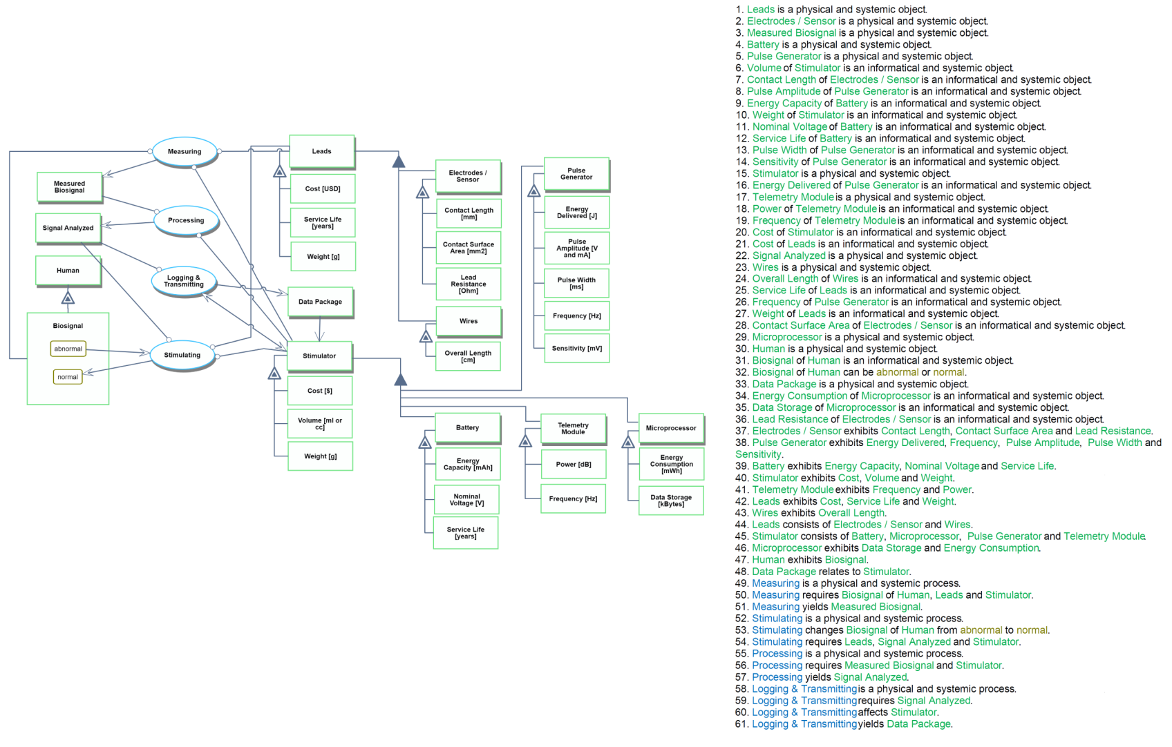
Provided below is an OPD and OPL of the 3BDES roadmap. The OPM shows the components that make up the device, their Figures of Merit (FOMs), and the functions that take place to stimulate the bio-signal and change its states.
Figures of Merit
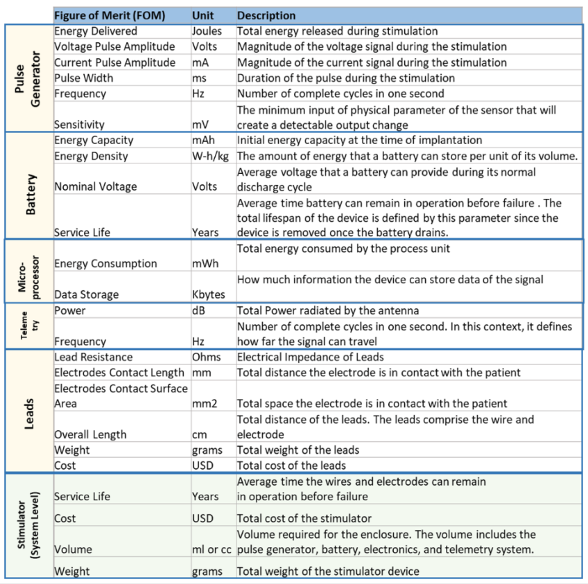
The table below lists the different FOMs that can be assessed for this technology roadmap. They are allocated by component (note that Telemetry refers to the Communications Module, assumed to be integrated into the Microcontroller).
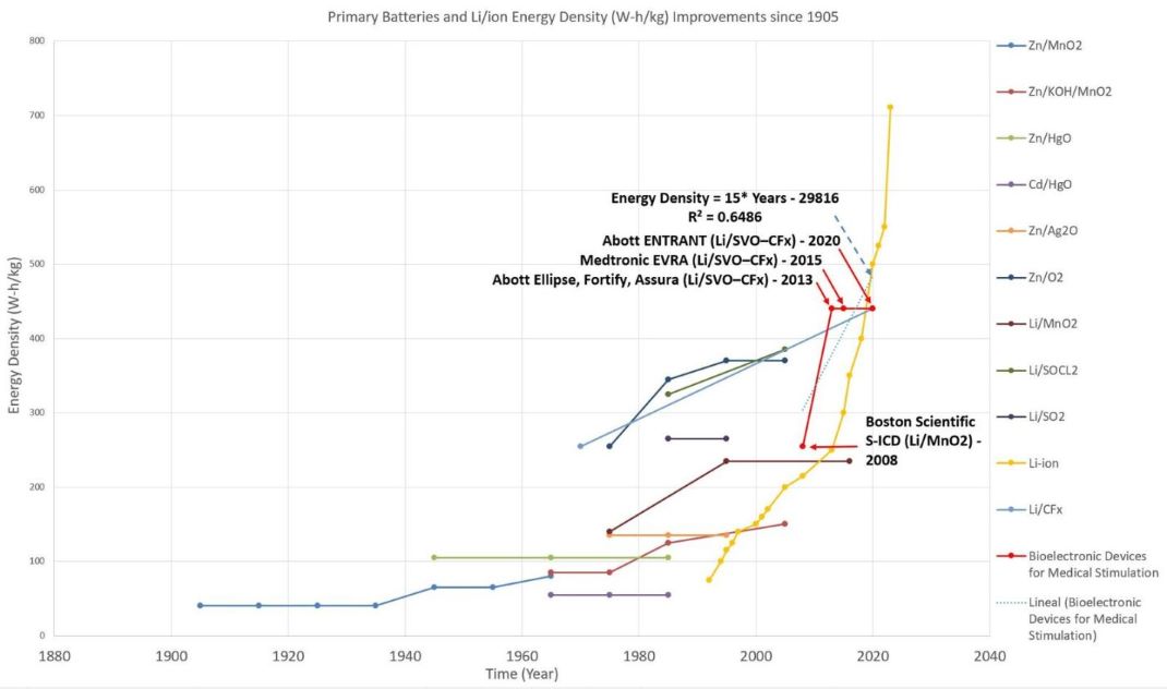
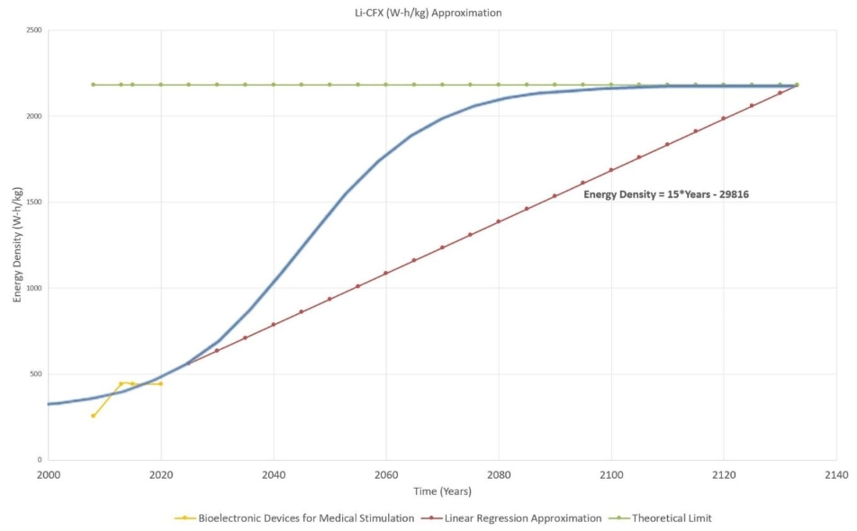
In the two figures below, the team sketched approximately the timeline and modeled the rate of improvement of Energy Density by using a linear regression and S shape (Manually). With the current data, the technology's improvement rate is 1.326 [W-h/g] per year. [9] [10] [11] [12] [13] [14] [15] [16]
"The Li-CF𝑥 primary battery was commercialized in 1970. It offers many advantages such as a high energy and high-power density, excellent shelf-life, applicability in a wide temperature range (−60 to +60 °C), and a relatively easy-to-source and economic composition" [17]. This is why companies such as Abbott and Medtronic use these batteries instead of the Li/MNO2 batteries that Boston Scientific uses in their current products. Therefore, the primary assumption for this analysis is that the Li-CFx batteries will dominate battery technology for a long time. However, as seen from the previous graph, battery technologies do not fully progress through the S curve, as in the case of Li-ion technology, since usually, a new technology disrupts the current composition and pushes the technology forward with a new battery composition. This is evident if we analyze the red line, which jumps drastically from 0.255 (W-h/g) to 0.440 (W-h/g). Also, according to the presented data, the Li/MnO2 composition has stagnated in the past two decades, while the Li-CFx composition has improved over the same time.
The theoretical limit for Li-CFx batteries can be determined by analyzing the battery's chemical composition. "Fluorinated carbons (CFx) ... may deliver a maximum theoretical capacity of 865 mAh/g when used as electrode material in a primary lithium battery [9-14]. This capacity corresponds to the overall electrochemical conversion of C–F bonds into amorphous carbon. Indeed, in a primary lithium battery, the electrochemical process in a fluorinated carbon electrode involves the breaking of one C–F bond by supplying an electron from the external circuit" [18]. Therefore, the theoretical limit of the Li-CFx technology is 2.180 W-h/g when graphite is fully fluorinated. [17]
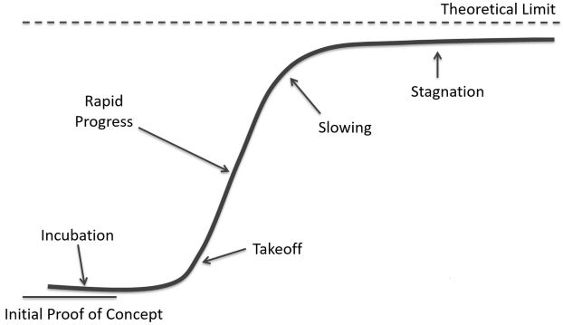
Using the figures above with the S-Curve reference as shown below [20], we estimate that the current technology is in the "Takeoff" stage. The reason is that the rate of improvement for the Li-CFx has not slowed down since 1970 compared to other primary batteries (cannot be recharged after one use and end up getting discarded after discharge [20]) that stagnated over time. In addition, other battery compositions have not had a different increase in energy density than the Li-CFx. These reasons along with the high theoretical limits show that the battery still has much to offer, which means improvements in the service life of bioelectronic devices' technology. However, even if the theoretical limit is five times the capacity that we have today, it is most likely that a new lithium composition will take over Li-CFx as seen in the history of batteries over the years shown in the first figure above.
Alignment with Company Strategic Drivers
The table below shows some potential strategic drivers and alignment of the Biodevices for Electrical Stimulation roadmap.
| Number | Strategic Driver | Alignment and Targets |
|---|---|---|
| 1 | To have a device service life of 20 years to last the average patient in need of electrical stimulation therapy a much longer time without the need for a replacement. | The [3BDES] technology roadmap considers different Figures of Merit for the battery such as energy density [W-h/g] and service life [years]. For alternatives which use the body as a source of power, calculations can be done to convert to an equivalent energy density and service life. The roadmap is aligned to this strategic driver. |
| 2 | To have a modular design that allows for treatment of different conditions while reusing at least 50% of the components and saving costs in the long term. | The [3BDES] technology roadmap contains elements with different needs and applications that create tension on others for the purpose of modularity, as shown by the DSM. The roadmap is not aligned to this strategic driver. |
| 3 | To have a battery weight of 10 grams, which equates to about half of the competition in the lead pacemaker market. | The [3BDES] technology roadmaps considers the architecture of different components and assumes that most of the weight in a electric stimulation device comes from the battery, thus neglecting the weight of other components for comparison. FOMs exist to evaluate the weight. The roadmap is aligned to this strategic driver. |
The roadmap currently has a focus on the battery longevity of the device and with reference data from leadless pacemakers, it seems feasible to pursue a service life (notwithstanding outliers and procedural defects) of 20 years; thus, the roadmap is aligned with the first strategic driver. For the second strategic driver, while the roadmap is generic enough to cover all applications, there are many variables that are in tension (not to mention the current DSM might not fully support a fully modular design). Evaluating whether the technology can truly be modularized requires both technical assessment for feasibility and a financial assessment for net present value to determine whether to pursue this strategic driver; therefore, the roadmap is currently not aligned. Lastly, the third strategic driver is focused around establishing a device footprint that is smaller than potential competitors (not considering leadless pacemakers and similar electrical stimulators of a smaller footprint).
Positioning of Company vs. Competition
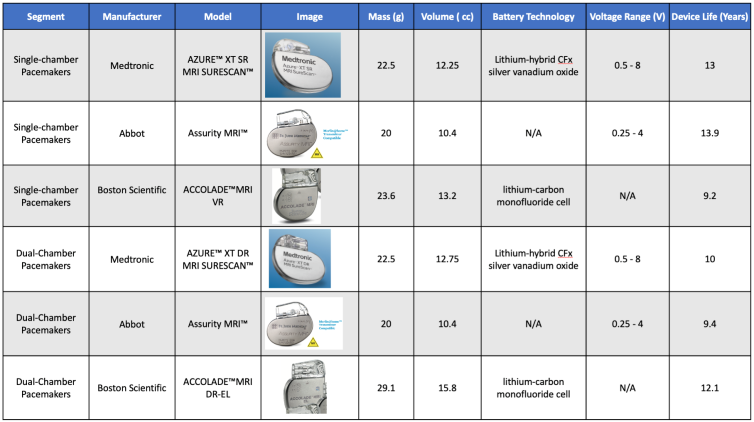
The table below shows a comparison of FOMs from related / competitive companies for a reference scenario using cardiac pacemakers in single-chamber and dual-chamber market segments. We chose cardiac pacemakers because it’s a relatively mature application with some publicly available specifications across multiple companies. Even so, some of the key data points are kept confidential by the companies and therefore was not available; those columns were marked “N/A” for now.
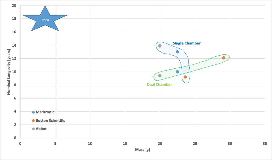
The above figure compares the overall mass of the pacemakers vs their listed longevity under a baseline therapy program. They are separated into two different clusters, one for a single chamber of the heart and one for dual chambers of the heart. In the context of these FOMs the Abbot product seems to chart the overall pareto front in both clusters based on the publicly available information. Additionally it looks like some companies use a common shared platform (identical mass and volumes) to serve the single and dual chamber product lines. Boston Scientific was the only one of the three to offer an extended life product with a significantly bigger battery at the expense of mass and volume.
Technical Model
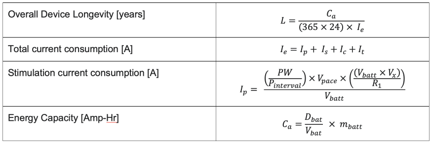
To build the mathematical model focusing on the Longevity FOM [years], we used the Governing Equations below:
The variables are represented as follows:
- Ca is the energy capacity of the battery [A-hr].
- Dbat is the power density of the battery [W-h/g].
- Vbat is the nominal voltage of the battery [V].
- mbat is the weight of the battery [g].
- PW is the pulse width of the pacing signal [s].
- Pint is the pacing interval [s].
- Vpace is the pacing voltage [V].
- Vx is the pacing multiple [constant].
- R1 is the lead resistance [Ω].
- Is is the average sense amplifier current [μA].
- Ic is the average control current [μA].
- It is the average telemetry current [μA].
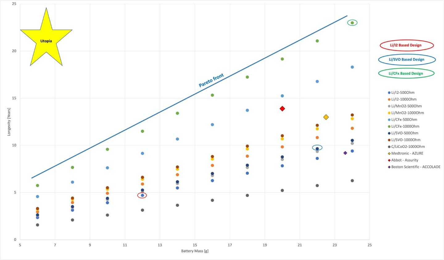
The morphological matrix with 3 different concepts is shown below, along with a tradespace of different scenarios and reference technologies from Abbott, Medtronic, and Boston Scientific. The tradespace is plotted along Longevity [years] over Battery Mass [g]:
The above tradespace illustrates a very linear relation between overall longevity of the device vs the mass of the battery in the range of batteries that we explored. Different configurations shift this linear line across the tradespace. This makes sense because the device life in this application is dominated by ability to provide pacing current to the heart. It also worth noting that the real-world products are behind the pareto front as there are probably several power and packaging factors that are not fully captured in our mathematical model.
One of the critical parameters in bioelectronic devices is the battery's longevity because it drives the device's service life. Primary batteries found in bioelectronic stimulators are the only battery compositions that can provide high currents during stimulation while providing low-level currents for the monitoring circuits. In addition, these batteries cannot be recharged since they utilize electrolytes contained within absorbent material or a separator and are thus termed dry cells. Therefore, once the battery depletes, the device is no longer useful and must be replaced to renew the battery. Surgery is needed to replace the battery. For these reasons, we used the longevity formula, obtained by combining the 4 governing equations, in the sensitivity analysis to analyze the variables that affected the device's service life. The analysis performed uses the following combined formula:
The gradient vector was built over the following variables:
For the design vector, we plugged in the baseline concept constants into following:
Xo = [Dbat, mbat, Vbat, PW, Vpace, VX, Pint, R1, IS, IC, It]
Xo = (0.57[W-h/g], 10 [g], 3[V], 0.0004[s], 5.6[V], 2[1], 1[s], 1000[Ohm], 0.000004[A], 0.000001[A], 0.000001[A])
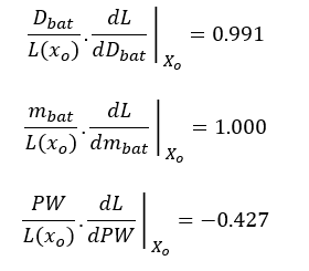
Upon solving for the derivatives with respect to each of the variables described in the variant vector, we arrived at the following conclusions, in order:
- Dbat - Power Density
Increasing the battery capacity by 1 mWh/g unit will increase the battery life by 0.036 years (13.14 days). This behavior is expected since increasing the power density means that the battery can deliver more energy and, consequently, extend the life of the device. Finding new battery compositions or improving current technologies is a viable option for optimization.
- mbat - Battery Weight
Increasing the battery weight by 1 gram will increase the battery longevity by 2.07 years. Medical device batteries are around 10 grams since device volume restrictions constrain the battery's weight. Increasing weight might not be a viable option for optimization.
- PW – Pulse Width
Increasing the pulse width by 1 μ𝑠 will decrease the battery's life by 0.022 years (8.03 days). The behavior is expected since increasing the pulse means more energy will be delivered to the patient. Therefore, the life of the battery will decrease more rapidly. Changing the pulse width is based on user treatment and cannot be modified arbitrarily to consume less energy. Therefore, decreasing pulse width might not be a viable option for optimization.
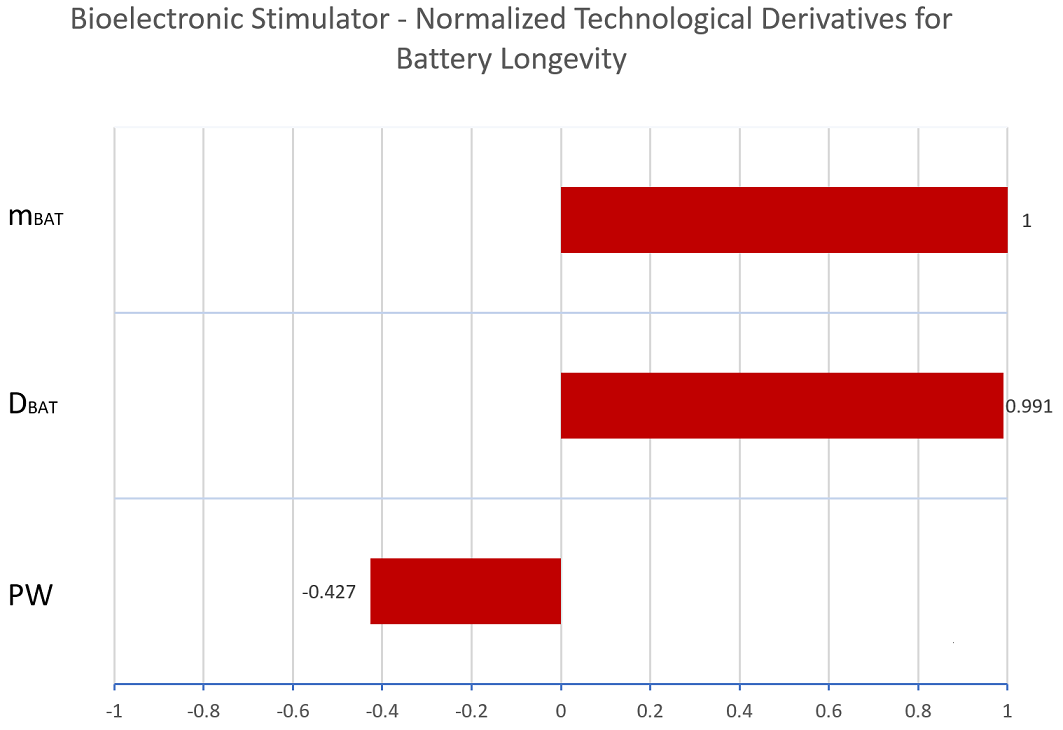
We then normalize the gradient vectors to show a tornado chart of sensitivities; the normalization values are shown below along with the tornado chart:
From the previous variables, the only feasible alternative to extend the life of the battery would be to increase the power density of the battery by improving the current Li/SVO-CFX technology or changing the battery to a new composition with better characteristics. All the other options are not feasible since they impact the weight, size, and aspects of the stimulation therapy and are not negotiable.
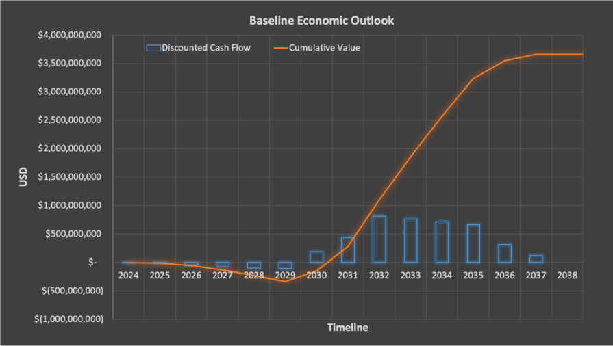
Financial Model
We developed the financial model [21] for our Bioeletronic Stimulator Device technology based on sales data, device costs, and profitability information that is public available for similar devices. We modeled a NPV scenario (using a 7% discount rate) that simulates a significant advance in the longevity FOM leading to significant market share capture. It assumes that these improvements would lead to being able to capture 14% market share (350,000k devices per year) for a period of about seven years. Devices would be priced at $5k per unit with a gross margin of 80%. It requires upfront R&D work on the order of $200M and a manufacturing investment of $240M. The overall NPV of such a scenario is about $3.6B.
Portfolio of R&D Projects and Prototypes
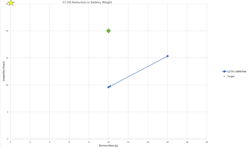
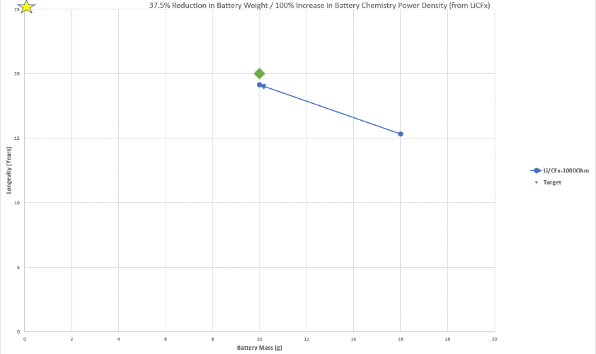
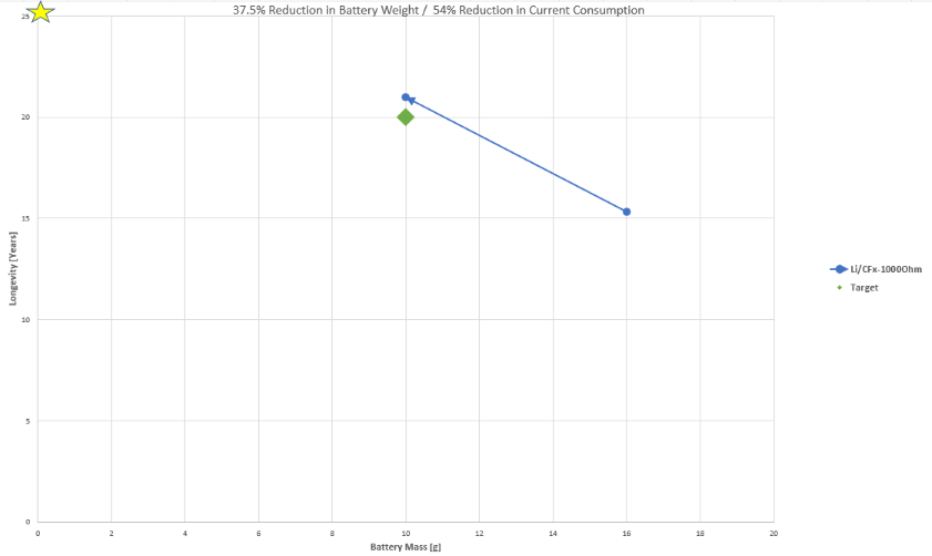
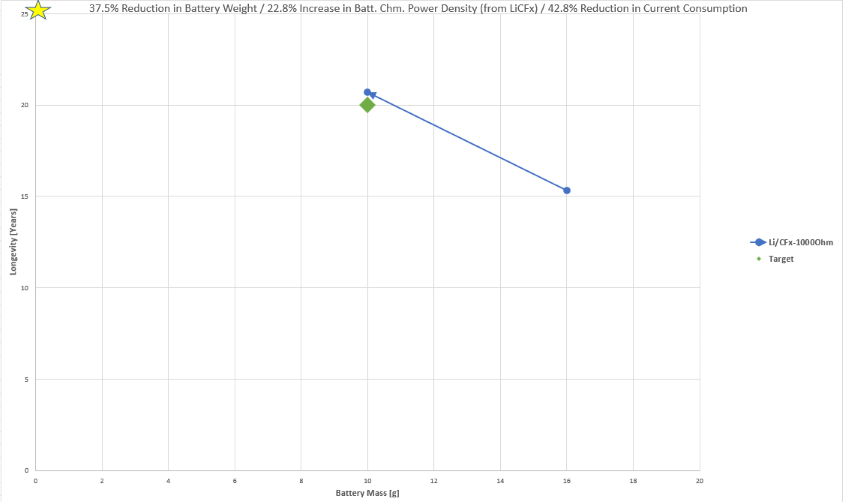
The insight from the technical model reveals which R&D projects should be undertaken. To this end, a baseline technology in the Pareto front was selected given its proximity to the target and some values in the technical model were tweaked accordingly against the strategic target to observe deltas in longevity and battery weight. Results are shown below.
As can be seen, the relationship between battery weight and longevity is nearly linear; as weight is reduced, so is the longevity (this is given by the governing equations). Furthermore, there is less reduction in current consumption required to meet the target than is the case for increase in battery chemistry power density. At double the power density (an effort that would in itself be costly), the target is still not reached; on the other hand, halving the current consumption leads to the baseline design meeting the target. As such, a slightly smaller reduction in current consumption and a significantly smaller increase in battery chemistry power density lead to the target being met with less constraints on either variable as shown below.
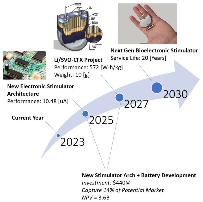
The emerging R&D initiatives from the analysis and their respective classification are shown in the table below.
| Project Title | Description | Classification |
|---|---|---|
| New Electronic Stimulator Architecture | Use specialized ICs for electronic components (especially within micro-controller) and reduce the current draw to ~10.5 uA. | This project is classified as R&D. Baseline already exists and mature technologies will be leveraged to produce a more efficient architecture. |
| Li/SVO-CFx Project | Reduce the weight of the battery to 10 grams and increase its power density to 0.572 W-h/g by investigating a Li/SVO-CFx hybrid battery. | This project is classified as R&D. This hybrid battery already exists in other technologies and the challenge becomes to infuse it to our electrical stimulator technology. |
Key Publications, Presentations, and Patents
Key Publications
- TRENDS IN CARDIAC PACEMAKER BATTERIES
Authors: Venkateswara Sarma Mallela, Ilankumaran, and N.Srinivasa Rao
Reference: https://www.ncbi.nlm.nih.gov/pmc/articles/PMC1502062/
Relevance: Since the introduction of the pacemaker, the battery has become the most critical element in medical stimulators because the devices need to operate for many years while stimulating. Half of the power is for cardiac stimulation, while the other half is for housekeeping tasks such as monitoring and data logging. In addition, batteries must be safe and reliable to avoid frequent replacements and, consequently, surgery.
During the past years, researchers have been working to find different battery compositions to make these batteries last longer. Medical devices started with Ni-Cd, then moved to Zn-Hg, Li-ion, Li-MnO2, and Li-CFx. All of these batteries have advantages and disadvantages. For example, some are volatile, discharge rapidly, have low energy density, cannot support high currents, etc. However, recent studies show that Li-SVO and Li-CFx can offer higher current densities without significant voltage drops within an acceptable volume and weight.
The relevance of this article is that it shows the past, current, and future trends in pacemaker batteries and invites the reader to investigate Li-SVO and Li-CFx batteries, which are the compositions used by all medical technology companies.
- BATTERY LONGEVITY OF IMPLANTABLE CARDIOVERTER-DEFIBRILLATORS AND CARDIAC RESYNCHRONIZATION THERAPY DEFRIBILLATORS: TECHNICAL, CLINICAL, AND ECONOMIC ASPECTS. AN EXPERT REVIEW PAPER FROM EHRA
Authors: Giuseppe Boriani, Josè Merino, David J Wright, Fredrik Gadler, Beat Schaer, Maurizio Landolina
Reference: https://academic.oup.com/europace/article/20/12/1882/4995002?login=false
Relevance: In recent years, the improved battery chemistries have brought clinical benefits, such as reducing replacements and complications during surgery. In addition, the improvement in battery technologies has reduced the long-term costs of device therapy by 30%. This has shifted the minds of users who see these devices as unaffordable.
The relevance of this article is that it outlines and discusses:
- The context of stimulators inside and outside the operating rooms
- The factors that affect device longevity
- Batteries chemistries
- The transparency of manufacturers in providing transparency about longevity calculations and data.
- Information about patient survival and its relation to device service life
- The economic, technical, and clinical benefits for the user and the doctors about changing the battery compositions.
- HIGH-ENERGY AND HIGH-POWER PRIMARY LI-CFX BATTERIES ENABLED BY THE COMBINED EFFECTS OF THE BINDER AND THE ELECTROLYTE
Authors: Haobin Huo, Sivaviswa Radhakrishnan, Leon L. Shaw, Károly Németh
Reference: https://doi.org/10.3390/batteries9050268
Relevance: During the past years, researchers have sought effective methods to deliver high energy and power using Lithium–carbon fluoride (Li-CFx) batteries. These densities have been possible by choosing the right binder and electrolyte in Li-CFx batteries to provide as high as 931 Wh/kg by controlling porosity, boron doping, electrolyte additives, and modifying the nano-structures of these materials.
The relevance of this article is that it shows the current state-of-the art of materials, methods, and chemistry behind high energy density Li-CFx batteries. In addition, it provides relevant information about the relationship between energy density and power density that justifies the use of these batteries in medical devices.
Patents
3 patents are of interest to the roadmap as of date, each preceded by a table containing patent information.
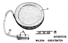
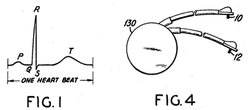
Patent "US 3057356 A" is the first documented patent in history that described the most widely used bioelectronic stimulator, the cardiac pacemaker (CP). Wilson Greatbatch, who is also the author of the patent, designed the CP. The patent was filed the same year Dr. William Chardack and Wilson Greatback implanted the pacemaker in a 77-year-old man and worked [22]. The pacemaker was possible for the advancement in the electronics industry that led to the discovery of the transistor (Patent US 2569347 A) in 1948 and introduced commercially in 1954 [23]. Before that, the word stimulator was vaguely used in patents such as US 2410499 (Stimulator) A and US 2609499 A (Muscle Stimulator). However, Greatbach's patent described the main components of the pacemaker as we know it today.
In the patent, Greatbach discusses the uses of the stimulator in medicine and considers the pacemaker technology as a potential substitute for a diseased or non-functional organ within the human body capable of performing physiological functions.
The reason why this patent is relevant for our study is because it discusses the architecture, function, and form of pacemakers as we know it today. This can be seen in the following passage of the patent:
"An electronic cardiac pacemaker for performing heart control functions comprising, in combination, a battery-powered, transistorized, pulse-producing circuit cast in a potting compound, a thin, wafer-like envelope formed about said pulse-producing circuit, a pair of spaced electrodes for contacting a section of cardiac tissue, and transmission means extending between said pulse producing circuit and said spaced electrodes, said envelope, electrodes, and transmission means being constructed from material compatible with the environment of the human body to permit their implantation therein."
For us, it is incredible that after 63 years, this technology has not changed, and we have only incorporated sustaining improvements over the years. However, the only thing this patent failed to predict is that current pacemakers use capacitor discharge to stimulate rather than a transistorized array. Still, overall, the technology is 90% accurate as today.
Patent US 3478746 A describes an aspect that the original Greatbach patent should have discussed: the feedback loop control system that allows the stimulator to work independently by sensing each natural heartbeat and resetting the Pacemaker pulse generator timing in response to it. In other words, the pacemaker stimulates only skipped beats or fails to function and does not compete with natural beats.
In Greathbach words:
- "...to provide an implantable cardiac Pacemaker which operates only upon a demand signal from the heart itself"
- "...to provide an implantable device which senses any arrest of normal cardiac activity and subsequently delivers timed electrical pulses to the heart in such a way as to restore a more normal cardiac rhythm.
- "...to provide an implantable cardiac Pacemaker whose battery supply is greatly reduced during normal cardiac activity when auxiliary stimulation from the pacemaker is not needed.
- "...to provide an implantable cardiac Pacemaker whose activity is governed by sensory impulses received over the same electrodes over which a stimulation impulse may later be supplied, so that no extra electrodes are needed for the sensory function."
This is why this patent is of interest to us. Since 1965, pacemakers have used the same architecture as we know it today, and there have only been sustaining improvements in this technology, e.g., better mechanical connections, electrodes, leads, sensing, software, telemetry, and battery improvements. Examples can be shown in the table below:
| Patent | Date Published | Title | Filed by (Person/Company) |
|---|---|---|---|
| US 3454012 A | 1969-07-08 | Rechargeable Heart Stimulator | Raddi William J |
| US 3596662 A | 1971-08-03 | Electrode for Cardiac Stimulator | Bolduc; Lee R. (Medtronic Inc.) |
| US 4026305 A | 1977-05-31 | Low current telemetry system for cardiac pacers | Brownlee; Robert R. et al. (Research Corporation) |
| US 4112953 A | 1978-09-12 | Pacer stimulator with improved lead connector | Shanker; Irvin Paul et al. (Medcor, Inc. ) |
| US 20070075905 A1 | 2007-04-05 | Radio frequency antenna for a wireless intravascular medical device | Denker; Stephen et al. (Kenergy, Inc.) |
| US 20230307965 A1 | 2023-09-28 | Implantable Pulse Generator Charging Alerts | Srivastava; Kyle et al. |
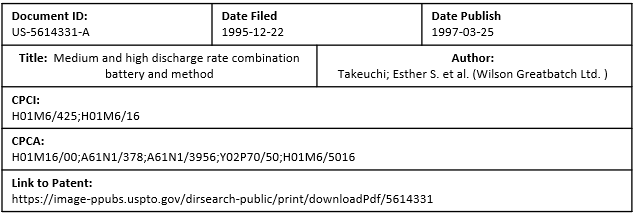
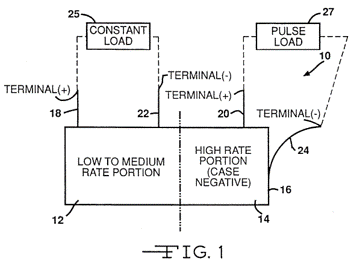
Patent US-5614331-A "describes a method of using a medium-rate CFx cell to power the circuitry of an implantable defibrillator while simultaneously using a SVO cell to provide the power supply under high-rate applications for the device. The advantage of this method is that all the high-power SVO energy is reserved for high-power applications such as charging a capacitor while the device monitoring function, for example, for monitoring the heartbeat, which requires low power requirements, is provided by the high capacity CF.sub.x system" [24]
This patent is of importance to us since it is the first patent that mentions that mixing high-capacity materials (CFx) with high-rate cathode materials (SVO) produces batteries suitable for biomedical stimulators.
These types of batteries provide "Low-level currents for the maintenance of electronic monitoring circuits as well as high-level currents during device activation." In other words, the battery can handle the pacing and defibrillation modes of the stimulator. These two modes are different in voltage and current consumption. Therefore, the battery will remain stable when both operations happen simultaneously.
The previous reasons explain why current medical devices and companies such as Abbott and Medtronic use these batteries: their high energy density and capacity within a small device. The battery can perform two stimulation modes while having a long battery life.
Technology Strategy Statement
Our target is to develop the next generation of long-lasting and low power bioelectronic stimulators with an Entry-into-Service of June 2030. To achieve the target of 20 years of service life, the company will invest in two R&D projects. The first project is the implementation of a new electronic architecture by 2025. The electrical team will replace components that are end of life (EOL) and non-recommended for new design (NRND) with specialized integrated circuits that draw ~43% less current and dissipate less energy during the stimulation and monitoring activities. The second project is an improved Li/SVO-CFX battery by 2027 that will provide ~23% more energy density (W-h/kg). These two projects will help us achieve our 2030 technical and business targets.
References
Section 1.1:
[1] Feinstein Institutes for Medical Research. (2023, September 18). Retrieved from: https://feinstein.northwell.edu/institutes-researchers/bioelectronic-medicine
[2] PNAS. (2023, September 18). Retrieved from: https://www.pnas.org/doi/10.1073/pnas.1919040116
[3] National Library of Medicine. (2023, September 18). Retrieved from: https://www.ncbi.nlm.nih.gov/pmc/articles/PMC6057139/
[4] Cochlear Implant reference image. Retrieved from: https://ablehearing.com/hearing-devices/cochlear-implants/
[5] Spinal Cord Stimulator reference image. Retrieved from: https://www.caringmedical.com/prolotherapy-news/reducing-risk-failed-back-surgery-syndrome/
[6] Deep Brain Stimulator reference image. Retrieved from: https://www.defeatingepilepsy.org/treatment-for-epilepsy/deep-brain-stimulation/
[7] Vagus Nerve Stimulator reference image. Retrieved from: https://www.saintlukeskc.org/health-library/understanding-vagus-nerve-stimulator-vns-placement
[8] Pacemaker reference image. Retrieved and modified from: https://www.hopkinsmedicine.org/health/treatment-tests-and-therapies/pacemaker-insertion
Section 1.4:
[9] "A 700W·h·kg−1 Rechargeable Pouch Type Lithium Battery", Li, Yang, Yu, et al.(2023, March 17). DOI: 10.1088/0256-307X/40/4/048201
[10] "Thermodynamic analysis on energy densities of batteries", Zu, Li. (2015, December 15). DOI: 10.1039/c0ee00777c
[11] "The Center for Reasearch on Extreme Batteries", Wachsman, Lundgren, Takeuchi, et al. (2017, June 08)
[12] Boston Scientific EMBLEM™ MRI S-ICD System. (2023, October 11). Retrieved from: https://www.bostonscientific.com/en-US/products/defibrillators/emblem-s-icd-system.html?gclid=Cj0KCQjw7JOpBhCfARIsAL3bobdBU-CKnhwnED4aMLrr9joyzbZ9NrlBnYyE5coTh2iVZZMdqv5b0kEaAgsdEALw_wcB
[13] Entrant™ Dual-Chamber ICD. (2023, October 11). Retrieved from: https://www.cardiovascular.abbott/content/dam/cv/cardiovascular/hcp/products/cardiac-rhythm-management/entrant-icd/documents/crm-entrant-dual-chamber-icd-order-info-us.PDF
[14] Entrant™ Single-Chamber ICD. (2023, October 11). Retrieved from: https://www.cardiovascular.abbott/content/dam/cv/cardiovascular/hcp/products/cardiac-rhythm-management/entrant-icd/documents/crm-entrant-icd-single-chamber-order-info-us.PDF
[15] Medtronic - EVERA MRI XT Family Datasheets. (2023, October 11). Retrieved from: https://www.medtronic.com/us-en/healthcare-professionals/products/cardiac-rhythm/icd-systems/evera-mri.html
[16] Abott - ICD Family. (2023, October 11). Retrieved from: https://operativa.sk/wp-content/uploads/2020/10/crm_product_catalog-ICD.pdf
[17] "High-Energy and High-Power Primary Li-CFx Batteries Enabled by the Combined Effects of the Binder and the Electrolyte", Huo, Radhakrishnan, Shaw. (2023, May 9th) https://doi.org/10.3390/batteries9050268
[18] "Pushing the theoretical limit of Li–CFx batteries using fluorinated nanostructured carbon nanodiscs", Ahmad, Dubois, Guérin, et al. (2015, November) https://doi.org/10.1016/j.carbon.2015.07.073
[19] Olivier L. de Wek, Technology Roadmapping and Development, 1st Edition, Springer. (2022)
[20] "Classifications of Cells or Batteries", University of Washington. (2023, October 11th). Retrieved from: https://depts.washington.edu/matseed/batteries/MSE/classification.html#:~:text=A%20primary%20cell%20or%20battery,are%20thus%20termed%20dry%20cells.
Section 1.8
[21] de Weck, O. L. (2023). Technology Valuation and Finance [Lecture 17 slide]. 16.887
Section 1.10.2
[22] "The invention of the cardiac pacemaker", U.S. Department of Veterans Affairs (2023, October 29) .Retrieved from: https://www.research.va.gov/research_in_action/The-invention-of-the-cardiac-pacemaker.cfm
[23] "First Commercial Transistor", BBC. (2023, October 29). Retrieved from: https://www.bbc.co.uk/ahistoryoftheworld/objects/LIDD7lI4QumcPPyZenkdRQ
[24] "Double Current Collector Cathode Design Using Mixtures Of Two Active Materials For Alkali Metal Or Ion Electrochemical Cells", Gan and Tekeuchi (Feb 17, 2004). Retrieved from: https://image-ppubs.uspto.gov/dirsearch-public/print/downloadPdf/6692865
