Difference between revisions of "Radio Frequency Counter UAS System"
| (77 intermediate revisions by 3 users not shown) | |||
| Line 1: | Line 1: | ||
Roadmap Creators: | Roadmap Creators: | ||
* [Sam Youngdale] | * [https://www.linkedin.com/in/samyoungdale Sam Youngdale] | ||
* [Chris Emerson] | * [https://www.linkedin.com/in/emerson-c Chris Emerson] | ||
* [https://www.linkedin.com/in/jumpei-sakamoto-8a1b90294 Jumpei Sakamoto] | * [https://www.linkedin.com/in/jumpei-sakamoto-8a1b90294 Jumpei Sakamoto] | ||
Time Stamp: 5 November 2024 | |||
Time Stamp: | |||
=Radio Frequency Counter UAS System= | =Radio Frequency Counter UAS System= | ||
| Line 13: | Line 11: | ||
==Roadmap Overview== | ==Roadmap Overview== | ||
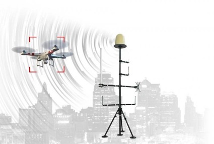
Counter-Unmanned Aircraft Systems (C-UAS) are technologies developed to detect, track, and neutralize unmanned aerial vehicles (UAVs) in situations where they pose security threats. With the proliferation of drones around the world, C-UAS is essential to the future airspace security landscape. C-UAS are modular and interoperable with numerous platforms. Demonstrated technologies include radar, electro-optical/infrared, acoustic, and radio frequency sensors for drone detection, as well as communication signals jamming, cyber takeover, and directed energy applications (laser and electromagnetic) for drone mitigation. Due to the variety of C-UAS configurations, our roadmap focuses on radar detection and radio frequency (RF) jamming. | |||
[[File:Detection_overview.jpg|frameless|600px]] | |||
<br> | |||
https://www.caci.com/cuas | |||
| Line 19: | Line 23: | ||
==DSM Allocation== | ==DSM Allocation== | ||
[[File:DSM_2RFC.png|frameless|1000px]] | |||
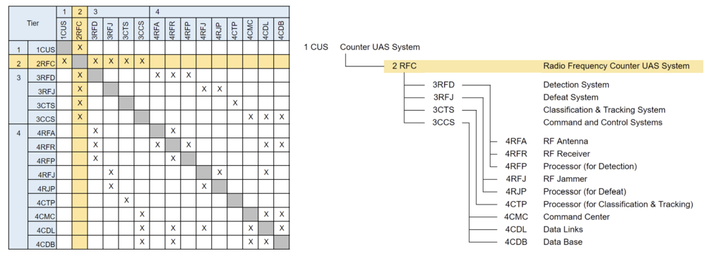
The above 2RFC tree shows the relationship between some systems related to the Counter UAS system that uses radio frequency as for detection and defeat. This tree says that the Counter UAS system consists of the detection system (3RFD), defeat system (3RFJ), classification & tracking system (3CTS), and command and control system (3CCS). In addition, these subsystems require several components such as an RF antenna (4RFA), RF jammer (4RFJ), a processor for classification and tracking (4CTP), command center (4CMC), and so on. As this DSM shows, The DSM indicates that each component is coupled to function as an RF counter UAS system. | |||
==Roadmap Model using OPM== | ==Roadmap Model using OPM== | ||
[[File:OPD_2RFC.jpg|frameless|800px]] | |||
[[File:OPL_2RFC.png|frameless|500px]] | |||
==Figures of Merit (FOM)== | ==Figures of Merit (FOM)== | ||
[[File:FOM Table_2RFC.PNG|frameless|800px]] | |||
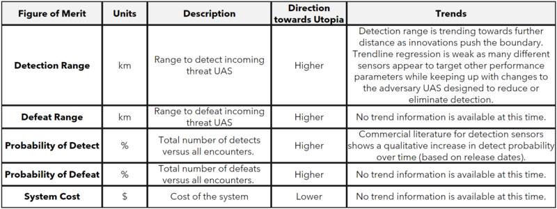
The table above summarizes a number of different Figures of Merit (FOM) for the C-UAS System. The complete system that detects and defeats will have similar FOMs on either side of the chain, and we've selected to focus on Detect as the key FOM. Detect ranges are one of the more widely publicly available data metrics for such systems. However, each entity may not utilize the same metrics for comparison. This study makes the assumption that detection range metrics from different suppliers are one-to-one. | |||
==Alignment with “Company” Strategic Drivers== | |||
===FOM Targets=== | |||
Based on the recent proliferation of UAS, there should be a need to address the case of UAS misuse. The company's strategic drivers and FOM targets based on this need are considered to be as follows. | |||
[[File:Strategic Driver 2RFC.png|frameless|700px]] | |||
==Position of Company vs. Competition== | |||
===FOM charts=== | |||
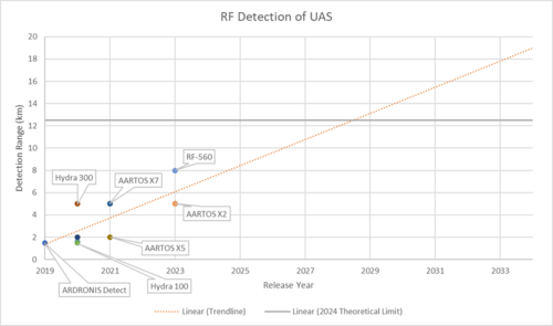
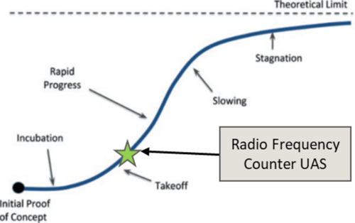
While the FOMs listed above are important indicators for measuring system performance, not all data for products currently on the market are publicly available. This section presents charts only for detection ranges for which data is publicly available, and comparisons can be made between products. | |||
[[File:FOM_table_2RFC.png|frameless|600px]] | |||
[[File:FOM_graph_2RFC.png|frameless|500px]] | |||
[[File:State_2RFC.png|frameless|500px]] | |||
==Technical Model== | |||
===Morphological Matrix and Tradespace=== | |||
Numerous design vectors determine the system, and it is impossible to list them all. Therefore, three representative decision variables are presented here. | |||
[[File:Morphological Matrix 2RFC.png|frameless|700px]] | |||
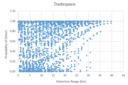
The Tradescope based on the combination of these decision variables is as follows. Typically, a performance versus cost comparison is typical, but considering that cost estimation is currently difficult, a Tradescope was created for the two indicators that will undergo sensitivity analysis later. As explained in the section on sensitivity analysis, the parameters of the UAS being detected are also taken into consideration here. | |||
[[File:Tradespace 2RFC.png|frameless|500px]] | |||
Many results show detection probabilities close to 1, and most of these are combinations with high antenna gain. However, it should be noted that high-gain antennas have high directivity, which narrows the detection range compared to omnidirectional antennas. Therefore, compensation, such as appropriately integrating multiple antennas to cover the same area, is necessary. | |||
===FOM Sensitivity=== | |||
The FOM of the counter UAS system is shown above. Among them, we formulate the detection range and probability of detect and evaluate their sensitivity. | |||
The variables used in the formula and their reference values are listed below. | |||
[[File:Variables Reference 2RFC.png|frameless|400px]] | |||
====Detection Range==== | |||
[[File:Detection Range formula.png|frameless|500px]] | |||
Here, GTx, PTx, and f are values determined by the UAS to be detected, but considering that the system's performance varies depending on the detection target, we will check the impact of these values. | |||
When the partial derivatives of each variable are calculated, the partial derivatives for all variables except f are low values. Therefore, the influence of these variables on the detection distance, which is an important index in evaluating the performance of the system, is easy to interpret. | |||
Next, we evaluate the sensitivity of the detection distance d to each variable. Here, the rate of change in the detection distance is shown for a 1% increase in each variable from the reference value. | |||
The results show that improving the receiver's receiver sensitivity is strongly influenced by improving the detection distance. It is necessary to construct a system that can detect UAS even when the reception level is low. | |||
[[File:Detection Range tornado.png|frameless|500px]] | |||
====Probability of Detect==== | |||
[[File:Probability of detect formula.png|frameless|500px]] | |||
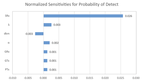
Here, since the detection probability follows a logistics function, the result of the partial differentiation of each variable shows a sigmoidal slope. Thus, a positively large value of the partial derivative implies a higher probability of detection. | |||
Next, we evaluate the sensitivity of the probability of detection to each variable. Here, the rate of change in the detection distance is shown for a 1% increase in each variable from the reference value. | |||
The results show that improving the receiver's receiver sensitivity is strongly influenced by improving the probability of detection. Despite the different indicators and different derivation assumptions in the equations, the most contributing variables are consistent with the results for detection distance, and the results for each are considered plausible. | |||
[[File:Probability of detect tornado.png|frameless|500px]] | |||
==Key Publications and Patents== | |||
[[File:Pub&Patent 2RFC.png|frameless|1000px]] | |||
==Financial Model== | |||
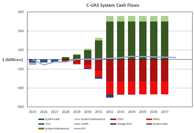
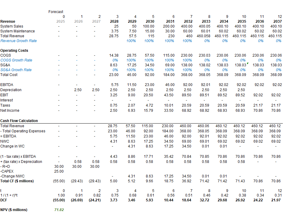
Our analysis is prepared from the perspective of a new entrant targeting fixed counter-UAS systems. We assess the total addressable product market is currently $1.2B, growing at a 24.7% CAGR, and forecast our future sales to be 6% of the market. Our discounted cash flows account for revenues from sales of C-UAS systems and recurring system maintenance, as well as research and development (R&D) costs, CAPEX required to build a sufficient manufacturing footprint, and operating expenses (COGS, SG&A, Working Capital) necessary to produce and sell our systems. Ultimately, this model projects a positive Net Present Value of $71.82M and our summary of cash flows and key assumptions are depicted below. | |||
Assumptions: | |||
*C-UAS System requires $90M R+D expenditure, evenly distributed over 3 years. | |||
*Manufacturing Facility is a one-time $25M CAPEX in year 1, depreciated straightline over 10 years. | |||
*Project timeline is 13 years (3 years of R+D plus a 10-year useful product life before C-UAS system is obsolete) | |||
*Sales grow from $25M to $400M over 4-years and then stabilize at a 5% growth rate. | |||
*Cost of goods sold (COGS) are 50% of Sales in hardware industries. | |||
*SG&A Expenses are 30% of Sales in hardware industries | |||
*Project is all-equity financed (no interest expense) | |||
*10.25% Discount Rate | |||
*23% Corporate Tax Rate | |||
[[File:CUAS Cash Flows.png|Center|Summary of Cash Flows]] | |||
[[File:CUAS NPV Analysis1.png|Center|NPV Analysis]] | |||
==List of R&D Projects== | |||
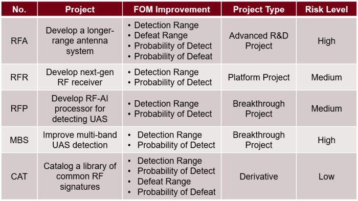
===Develop a more sensitive antenna system [RFA]=== | |||
An antenna system capable of long-range and wide-area UAS detection is developed by combining directional antennas capable of detecting long-range radio waves. Ensuring sufficient coverage requires appropriate positioning of multiple antennas, enabling proper mobility, or a combination of these methods. As the optimal arrangement varies depending on the frequency band, establishing technology that allows flexible design of antenna selection and arrangement tailored to the characteristics of the frequency band and the specific features of the installation site is essential. | |||
===Develop next-gen RF receiver [RFR]=== | |||
Design and test next-generation RF amplifiers capable of resolving lower amplitude signals through the use of amplification techniques, lower-noise receivers, and out-of-band noise rejection. Additional considerations such as multi-receiver parallelization and spectral gating. | |||
===Develop RF-AI processor for detecting UAS [RFP]=== | |||
A signal processing algorithm utilizing AI is constructed to develop a processor capable of accurately detecting and classifying UAS. In areas requiring vigilance, the presence of radio waves acting as noise is anticipated, making it necessary to appropriately distinguish between noise and the target UAS. Additionally, a learning algorithm and server integration are required to adapt in real-time to the continuously evolving UAS being developed. Furthermore, it is essential to note that computational load must be minimized to address UAS approaching at high speeds effectively. | |||
===Develop multi-band RF sensing [MBS]=== | |||
Utilize new low-TRL RF signal processing capabilities to integrate multi-band RF support. This will allow for simultaneous sampling of multiple frequency bands to increase probability of detect, and negate frequency-hopping as a counter UAS mitigation. | |||
===Catalog RF Signatures Library [CAT]=== | |||
Derivative project to measure and categorize an extensive list of commercial and known UAS spectrums to allow for faster identification. Additionally, known UAS capabilities will be linked and available for UAS defeat. | |||
[[File:RandD Table.png|Left|R&D Table|700px]] | |||
[[File:C-UAS_R&D_Opportunities.PNG|Right|R&D Opportunities|400px]] | |||
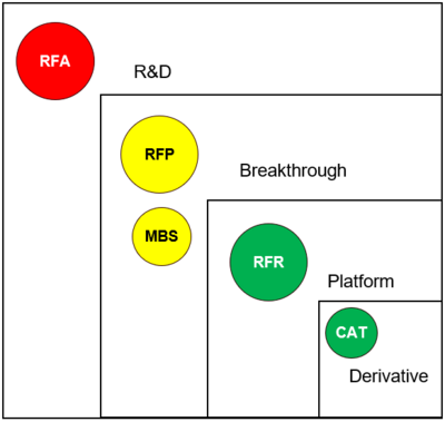
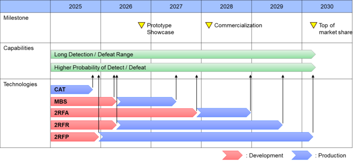
Each technological development will contribute to the improvement of FOMs and increase the value of the total system, thereby ensuring its superiority in the market. Since continuous improvement of these technological developments is considered possible and necessary, they must continue to be developed after commercialization to maintain market superiority. | |||
[[File:2RFC Milestone.png|Left|R&D Table|700px]] | |||
==Technology Strategy Statement== | |||
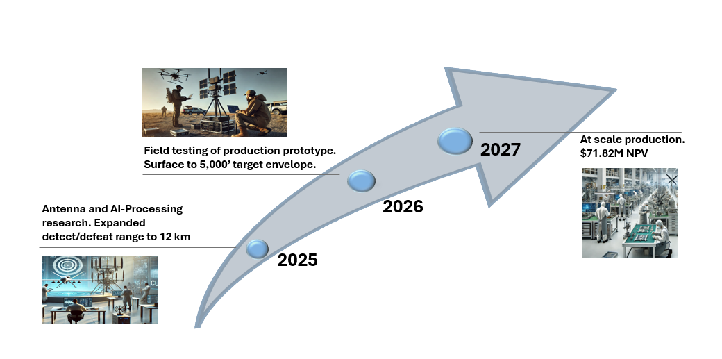
The technology strategy for our new Counter-UAS system focuses on leveraging advanced RF detection and defeat capabilities to effectively neutralize Group 1 drones in complex operational environments. By integrating cutting-edge signal processing algorithms with adaptive RF transmission techniques, the system will provide real-time identification, tracking, and disruption of drone threats omnidirectionally at ranges up to 12km and altitudes from surface to 5,000ft AGL. To launch this product in 2028, our company plans to invest Research and Development into high-gain, multi-band, and beamforming antennas as well as AI-powered signal processing. This will progress to a field prototype testing campaign in 2026 and will culminate with at-scale production of our commercial system in 2028. | |||
[[File:Tech_Roadmapping_Swoop.png|Center|]] | |||
Latest revision as of 06:24, 26 November 2024
Roadmap Creators:
Time Stamp: 5 November 2024
Radio Frequency Counter UAS System
Roadmap Overview
Counter-Unmanned Aircraft Systems (C-UAS) are technologies developed to detect, track, and neutralize unmanned aerial vehicles (UAVs) in situations where they pose security threats. With the proliferation of drones around the world, C-UAS is essential to the future airspace security landscape. C-UAS are modular and interoperable with numerous platforms. Demonstrated technologies include radar, electro-optical/infrared, acoustic, and radio frequency sensors for drone detection, as well as communication signals jamming, cyber takeover, and directed energy applications (laser and electromagnetic) for drone mitigation. Due to the variety of C-UAS configurations, our roadmap focuses on radar detection and radio frequency (RF) jamming.
DSM Allocation
The above 2RFC tree shows the relationship between some systems related to the Counter UAS system that uses radio frequency as for detection and defeat. This tree says that the Counter UAS system consists of the detection system (3RFD), defeat system (3RFJ), classification & tracking system (3CTS), and command and control system (3CCS). In addition, these subsystems require several components such as an RF antenna (4RFA), RF jammer (4RFJ), a processor for classification and tracking (4CTP), command center (4CMC), and so on. As this DSM shows, The DSM indicates that each component is coupled to function as an RF counter UAS system.
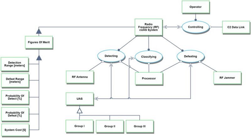
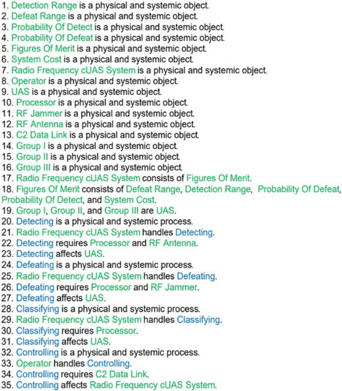
Roadmap Model using OPM
Figures of Merit (FOM)
The table above summarizes a number of different Figures of Merit (FOM) for the C-UAS System. The complete system that detects and defeats will have similar FOMs on either side of the chain, and we've selected to focus on Detect as the key FOM. Detect ranges are one of the more widely publicly available data metrics for such systems. However, each entity may not utilize the same metrics for comparison. This study makes the assumption that detection range metrics from different suppliers are one-to-one.
Alignment with “Company” Strategic Drivers
FOM Targets
Based on the recent proliferation of UAS, there should be a need to address the case of UAS misuse. The company's strategic drivers and FOM targets based on this need are considered to be as follows.
Position of Company vs. Competition
FOM charts
While the FOMs listed above are important indicators for measuring system performance, not all data for products currently on the market are publicly available. This section presents charts only for detection ranges for which data is publicly available, and comparisons can be made between products.
Technical Model
Morphological Matrix and Tradespace
Numerous design vectors determine the system, and it is impossible to list them all. Therefore, three representative decision variables are presented here.
The Tradescope based on the combination of these decision variables is as follows. Typically, a performance versus cost comparison is typical, but considering that cost estimation is currently difficult, a Tradescope was created for the two indicators that will undergo sensitivity analysis later. As explained in the section on sensitivity analysis, the parameters of the UAS being detected are also taken into consideration here.
Many results show detection probabilities close to 1, and most of these are combinations with high antenna gain. However, it should be noted that high-gain antennas have high directivity, which narrows the detection range compared to omnidirectional antennas. Therefore, compensation, such as appropriately integrating multiple antennas to cover the same area, is necessary.
FOM Sensitivity
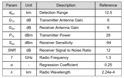
The FOM of the counter UAS system is shown above. Among them, we formulate the detection range and probability of detect and evaluate their sensitivity. The variables used in the formula and their reference values are listed below.
Detection Range
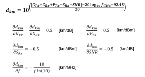
Here, GTx, PTx, and f are values determined by the UAS to be detected, but considering that the system's performance varies depending on the detection target, we will check the impact of these values.
When the partial derivatives of each variable are calculated, the partial derivatives for all variables except f are low values. Therefore, the influence of these variables on the detection distance, which is an important index in evaluating the performance of the system, is easy to interpret.
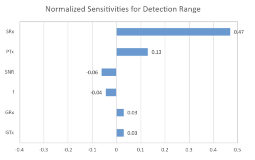
Next, we evaluate the sensitivity of the detection distance d to each variable. Here, the rate of change in the detection distance is shown for a 1% increase in each variable from the reference value.
The results show that improving the receiver's receiver sensitivity is strongly influenced by improving the detection distance. It is necessary to construct a system that can detect UAS even when the reception level is low.
Probability of Detect
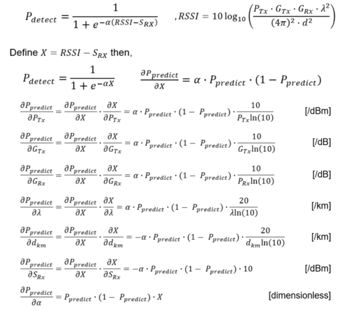
Here, since the detection probability follows a logistics function, the result of the partial differentiation of each variable shows a sigmoidal slope. Thus, a positively large value of the partial derivative implies a higher probability of detection. Next, we evaluate the sensitivity of the probability of detection to each variable. Here, the rate of change in the detection distance is shown for a 1% increase in each variable from the reference value.
The results show that improving the receiver's receiver sensitivity is strongly influenced by improving the probability of detection. Despite the different indicators and different derivation assumptions in the equations, the most contributing variables are consistent with the results for detection distance, and the results for each are considered plausible.
Key Publications and Patents
Financial Model
Our analysis is prepared from the perspective of a new entrant targeting fixed counter-UAS systems. We assess the total addressable product market is currently $1.2B, growing at a 24.7% CAGR, and forecast our future sales to be 6% of the market. Our discounted cash flows account for revenues from sales of C-UAS systems and recurring system maintenance, as well as research and development (R&D) costs, CAPEX required to build a sufficient manufacturing footprint, and operating expenses (COGS, SG&A, Working Capital) necessary to produce and sell our systems. Ultimately, this model projects a positive Net Present Value of $71.82M and our summary of cash flows and key assumptions are depicted below.
Assumptions:
- C-UAS System requires $90M R+D expenditure, evenly distributed over 3 years.
- Manufacturing Facility is a one-time $25M CAPEX in year 1, depreciated straightline over 10 years.
- Project timeline is 13 years (3 years of R+D plus a 10-year useful product life before C-UAS system is obsolete)
- Sales grow from $25M to $400M over 4-years and then stabilize at a 5% growth rate.
- Cost of goods sold (COGS) are 50% of Sales in hardware industries.
- SG&A Expenses are 30% of Sales in hardware industries
- Project is all-equity financed (no interest expense)
- 10.25% Discount Rate
- 23% Corporate Tax Rate
List of R&D Projects
Develop a more sensitive antenna system [RFA]
An antenna system capable of long-range and wide-area UAS detection is developed by combining directional antennas capable of detecting long-range radio waves. Ensuring sufficient coverage requires appropriate positioning of multiple antennas, enabling proper mobility, or a combination of these methods. As the optimal arrangement varies depending on the frequency band, establishing technology that allows flexible design of antenna selection and arrangement tailored to the characteristics of the frequency band and the specific features of the installation site is essential.
Develop next-gen RF receiver [RFR]
Design and test next-generation RF amplifiers capable of resolving lower amplitude signals through the use of amplification techniques, lower-noise receivers, and out-of-band noise rejection. Additional considerations such as multi-receiver parallelization and spectral gating.
Develop RF-AI processor for detecting UAS [RFP]
A signal processing algorithm utilizing AI is constructed to develop a processor capable of accurately detecting and classifying UAS. In areas requiring vigilance, the presence of radio waves acting as noise is anticipated, making it necessary to appropriately distinguish between noise and the target UAS. Additionally, a learning algorithm and server integration are required to adapt in real-time to the continuously evolving UAS being developed. Furthermore, it is essential to note that computational load must be minimized to address UAS approaching at high speeds effectively.
Develop multi-band RF sensing [MBS]
Utilize new low-TRL RF signal processing capabilities to integrate multi-band RF support. This will allow for simultaneous sampling of multiple frequency bands to increase probability of detect, and negate frequency-hopping as a counter UAS mitigation.
Catalog RF Signatures Library [CAT]
Derivative project to measure and categorize an extensive list of commercial and known UAS spectrums to allow for faster identification. Additionally, known UAS capabilities will be linked and available for UAS defeat.
Each technological development will contribute to the improvement of FOMs and increase the value of the total system, thereby ensuring its superiority in the market. Since continuous improvement of these technological developments is considered possible and necessary, they must continue to be developed after commercialization to maintain market superiority.
Technology Strategy Statement
The technology strategy for our new Counter-UAS system focuses on leveraging advanced RF detection and defeat capabilities to effectively neutralize Group 1 drones in complex operational environments. By integrating cutting-edge signal processing algorithms with adaptive RF transmission techniques, the system will provide real-time identification, tracking, and disruption of drone threats omnidirectionally at ranges up to 12km and altitudes from surface to 5,000ft AGL. To launch this product in 2028, our company plans to invest Research and Development into high-gain, multi-band, and beamforming antennas as well as AI-powered signal processing. This will progress to a field prototype testing campaign in 2026 and will culminate with at-scale production of our commercial system in 2028.
