Difference between revisions of "High-Speed Rail Safety"
| (13 intermediate revisions by 3 users not shown) | |||
| Line 40: | Line 40: | ||
The journey time TJ is the duration of transporting from location A to location B. By omitting the acceleration and deceleration near location A and B, TJ can be calculated using v_max as TJ = D/v_max, where D is the distance between location A and B and v_max is the maximum speed of the high-speed train. Considering the equilibrium state that the propelling force is equal to resisting forces, that is, | The journey time TJ is the duration of transporting from location A to location B. By omitting the acceleration and deceleration near location A and B, TJ can be calculated using v_max as TJ = D/v_max, where D is the distance between location A and B and v_max is the maximum speed of the high-speed train. Considering the equilibrium state that the propelling force is equal to resisting forces, that is, | ||
[[File:HSR- | [[File:HSR-formula_v_max.png|border|formula1]] | ||
| Line 105: | Line 105: | ||
The SCMAGLEV is propelled by electromagnetic force, not by friction between the vehicle and the rail. This difference is indicated by unique behavior in the tradespace. The SCMAGLEV has potential to decelerate hard enough to drop passengers from their seats, which means SCMAGLEV theoretically can operate beyond the “Drop” curve. However, from the viewpoint of passengers’ safety, it cannot go beyond “Drop” curve unless restraints or other instruments are installed to keep the passengers in their seats during emergency braking. | The SCMAGLEV is propelled by electromagnetic force, not by friction between the vehicle and the rail. This difference is indicated by unique behavior in the tradespace. The SCMAGLEV has potential to decelerate hard enough to drop passengers from their seats, which means SCMAGLEV theoretically can operate beyond the “Drop” curve. However, from the viewpoint of passengers’ safety, it cannot go beyond “Drop” curve unless restraints or other instruments are installed to keep the passengers in their seats during emergency braking. | ||
[[File:tradespace.png|frameless|800px|Trade Space ]] | [[File:tradespace.png|frameless|800px|Trade Space ]] | ||
| Line 148: | Line 149: | ||
'''Braking time''' | '''Braking time''' | ||
Improving braking time will have the largest impact on reducing the entire stopping time. Based on previous analyses, three options reduce the braking time: | Improving braking time will have the largest impact on reducing the entire stopping time. Based on previous analyses, three options reduce the braking time: | ||
# Increase the adhesion coefficient between the wheels and the track rails | # Increase the adhesion coefficient between the wheels and the track rails | ||
# Reduce the mass of a vehicle | # Reduce the mass of a vehicle | ||
# Increase the reference section against air. | # Increase the reference section against air. | ||
Research results by Arai, et al. [1] can be applied to increase the adhesion coefficient by spraying specific polymers between the train wheels and the track, development of which would take about five years. Mass reduction can be achieved with further improvements to bodies and motors, which would take about ten years. Increasing the reference section was also researched by Arai, et al, which can be brought to production within about ten years. | Research results by Arai, et al. [1] can be applied to increase the adhesion coefficient by spraying specific polymers between the train wheels and the track, development of which would take about five years. Mass reduction can be achieved with further improvements to bodies and motors, which would take about ten years. Increasing the reference section was also researched by Arai, et al, which can be brought to production within about ten years. | ||
Unfortunately, minimal stopping time is limited by passenger capabilities [2]. A “Comfort” deceleration rate of 1.5 m/s^2 allows passengers who are standing to hang on – above this deceleration rate passengers may not have the hand strength to maintain a grip on a hand hold. A “Drop” deceleration rate of greater than 2.5 m/s^2 will cause passengers to drop out of their seats. | Unfortunately, minimal stopping time is limited by passenger capabilities [2]. A “Comfort” deceleration rate of 1.5 m/s^2 allows passengers who are standing to hang on – above this deceleration rate passengers may not have the hand strength to maintain a grip on a hand hold. A “Drop” deceleration rate of greater than 2.5 m/s^2 will cause passengers to drop out of their seats. | ||
The | |||
The Gantt chart of R&D investments and their deployments are shown below. The large part of R&D investment, $5MM per year, will be on the improvement of the adhesion coefficient between a train and a rail, while investment in obstacle detection and monitoring/automatic reaction systems will continue in the next 5 years. (Note that the scale of the calendar changes after 2024 from 1 year/column to 2.5 years/column.) | |||
[[File:HSR-Gantt.png|frameless|1200px|hsr-gantt]] | |||
The following chart shows the goal value of each time by the R&D investments and deployments of the resulted techniques. The reduction of detection time would be gradually achieved because massive investment will be needed. Reaction time could be reduced in ten years by the automatic braking system. The improvement of braking time could be done by leveraging existing research results, while “Comfort” deceleration rate (1.5 m/s^2) and “Drop” deceleration rate (2.5 m/s^2) could be the hard wall to improved braking time, which would result in slow improvement (from 2029 in this table). | |||
[[File:stopping time.png|frameless|800px|stopping time ]] | [[File:stopping time.png|frameless|800px|stopping time ]] | ||
| Line 172: | Line 178: | ||
[5] Wikipedia, Concorde (Last edit 31 Oct 2019), https://en.wikipedia.org/wiki/Concorde | [5] Wikipedia, Concorde (Last edit 31 Oct 2019), https://en.wikipedia.org/wiki/Concorde | ||
== Keys Publications and Patents == | == Keys Publications and Patents == | ||
| Line 211: | Line 216: | ||
Anti-derailment systems come in several forms. Systems for low-speed use included additional hardware to stop the wheels from jumping the track and to keep the wheels close to the track once derailed. The image to the right, from US patent 2800861, renders one such system; US patent 3984637 specified the use of additional safety guide rails that are not load bearing. Later systems included improved wheel flange design to avoid the wheel riding up on the flange in curves. Improvements to truck (bogie) designs and couplers reduced tolerances in severe braking as well as reducing sway at high speed. | Anti-derailment systems come in several forms. Systems for low-speed use included additional hardware to stop the wheels from jumping the track and to keep the wheels close to the track once derailed. The image to the right, from US patent 2800861, renders one such system; US patent 3984637 specified the use of additional safety guide rails that are not load bearing. Later systems included improved wheel flange design to avoid the wheel riding up on the flange in curves. Improvements to truck (bogie) designs and couplers reduced tolerances in severe braking as well as reducing sway at high speed. | ||
Modern high speed rail designs typically include simulation tools to detect potential design issues that might cause instability at high speed. These tools are detailed in Nicholas Wilson , Robert Fries , Matthew Witte , Andreas Haigermoser , Mikael Wrang , Jerry Evans | Modern high speed rail designs typically include simulation tools to detect potential design issues that might cause instability at high speed. These tools are detailed in Nicholas Wilson, Robert Fries, Matthew Witte, Andreas Haigermoser, Mikael Wrang, Jerry Evans, and Anna Orlova (2011) "Assessment of safety against derailment using simulations and vehicle acceptance tests: a worldwide comparison of state-of-the-art assessment methods, Vehicle System Dynamics," 49:7, 1113-1157, DOI: 10.1080/00423114.2011.586706 from the International Journal of Vehicle Mechanics and mobility. This paper details mathematical models used to simulate vehicle resonant response and instability: | ||
* vehicle overturning | * vehicle overturning | ||
| Line 227: | Line 232: | ||
* Japan | * Japan | ||
* USA | * USA | ||
* Russia and the Commonwealth of Independent States (CIS) | |||
Many countries are moving away from physical testing facilities, which are typically long lengths of track with particular tests built in such as sharp curves and other potentially dangerous conditions, towards computer simulation, which can cover many more potential conditions at substantially reduced costs. At issue is the level of accuracy of the simulations and how to test if the simulations are representative of real life conditions. However, national safety standards are incorporating simulation as an acceptable test mechanism, proving simulation's growing acceptance with both engineers and safety administrators. | Many countries are moving away from physical testing facilities, which are typically long lengths of track with particular tests built in such as sharp curves and other potentially dangerous conditions, towards computer simulation, which can cover many more potential conditions at substantially reduced costs. At issue is the level of accuracy of the simulations and how to test if the simulations are representative of real life conditions. However, national safety standards are incorporating simulation as an acceptable test mechanism, proving simulation's growing acceptance with both engineers and safety administrators. | ||
| Line 235: | Line 240: | ||
The original track detection systems were humans observing conditions and then operating signals so that one train operator would know how far ahead the next train was. For the last twenty-five years modern safety systems for detecting track obstructions include camera and other optical systems to detect objects on the track ahead of the train. Some of these systems are train mounted, using lasers and detectors for range finding and including reflective components to allow these systems to detect objects not in straight line of sight of the train. Patent application US2004/0056182 A1 by Jamieson et al. describes on such system, a laser-based system with scanning lasers and receivers. The received echos from the lasers are then interpreted to determine if an object is obstructing the tracks. | The original track detection systems were humans observing conditions and then operating signals so that one train operator would know how far ahead the next train was. For the last twenty-five years modern safety systems for detecting track obstructions include camera and other optical systems to detect objects on the track ahead of the train. Some of these systems are train mounted, using lasers and detectors for range finding and including reflective components to allow these systems to detect objects not in straight line of sight of the train. Patent application US2004/0056182 A1 by Jamieson et al. describes on such system, a laser-based system with scanning lasers and receivers. The received echos from the lasers are then interpreted to determine if an object is obstructing the tracks. | ||
Other systems include track-side cameras and pattern detection | Other systems include track-side cameras and pattern detection and are becoming increasingly common to flag potential obstructions. State of the art systems include automatic detection and activation of brakes. The SCMAGLEV has no on-board operator; presumably while humans control the train remotely many of the emergency detection systems are partially or fully automated. | ||
'''Track condition''' | '''Track condition''' | ||
The design of the track has itself been adapted to support high speed rail. Superior rail, track, and bed design and implementation | The design of the track has itself been adapted to support high speed rail. Superior rail, track, and bed design and implementation respond to the increased longitudinal and latitudinal forces on the rails and these forces’ transfer through the ties and into the ballast and bed. The ability of the rails to withstand the extended braking force of a high-speed train coming to an emergency stop has been researched and modeled to ensure that the tracks do not distort under extreme loads. | ||
P.A. Costa, A. Colaço, R. Calçada, A.S. Cardoso, Critical speed of railway tracks. detailed and simplified approaches, (2014), doi: http://dx.doi.org/10.1016/j.trgeo.2014.09.003 details a simplified approach to modeling track embankments and compares this method to computationally complex methods. At issue is that the dynamic loads of high speed trains put much higher loads on the elastic components of the track system, potentially distorting track | P.A. Costa, A. Colaço, R. Calçada, A.S. Cardoso, "Critical speed of railway tracks. detailed and simplified approaches," (2014), doi: http://dx.doi.org/10.1016/j.trgeo.2014.09.003 details a simplified approach to modeling track embankments and compares this method to computationally complex methods. At issue is that the dynamic loads of high speed trains put much higher loads on the elastic components of the track system, potentially distorting track system components beyond tolerances, causing derailment. | ||
Jing Zeng & Qing Hua Guan (2008) Study on flange climb derailment criteria of a railway wheelset, Vehicle System Dynamics, 46:3, 239-251, DOI: 10.1080/00423110701313989 details how the form of the wheel flange needs to be different at higher speeds to avoid the wheel climbing onto the flange while moving through a curve. From this paper: "Based on the Coulomb’s friction law and the creep force laws, the Friction Formula and Creep Formula for the evaluation of derailment are derived, respectively. The analysis shows that the derailment coefficients of Friction Formula and Creep Formula required for derailment are increased considerably for smaller and negative yaw angles, and tend to the value of Nadal’s Formula at larger wheelset yaw angles." | Jing Zeng & Qing Hua Guan (2008) "Study on flange climb derailment criteria of a railway wheelset, Vehicle System Dynamics," 46:3, 239-251, DOI: 10.1080/00423110701313989 details how the form of the wheel flange needs to be different at higher speeds to avoid the wheel climbing onto the flange while moving through a curve. From this paper: "Based on the Coulomb’s friction law and the creep force laws, the Friction Formula and Creep Formula for the evaluation of derailment are derived, respectively. The analysis shows that the derailment coefficients of Friction Formula and Creep Formula required for derailment are increased considerably for smaller and negative yaw angles, and tend to the value of Nadal’s Formula at larger wheelset yaw angles." | ||
'''Braking''' | '''Braking''' | ||
Brake system design is the most critical issue for emergency braking right now. Converting the kinetic energy of a heavy and fast moving train to heat and then dissipating that heat is the current limiting factor for stopping distance. Disk brakes, as found under the Acela and other trains, is now considered state of the art. Load balancing systems are also deployed to avoid derailment while maximizing brake application when the back of the train is heavier than the front. Overall braking performance may be improved with driveline design changes, for example the Shinkansen has each axle powered, offering the opportunity to use the motors to further apply substantial decelerating forces | Brake system design is the most critical issue for emergency braking right now. Converting the kinetic energy of a heavy and fast moving train to heat and then dissipating that heat is the current limiting factor for stopping distance. Disk brakes, as found under the Acela and other trains, is now considered state of the art. Load balancing systems are also deployed to avoid derailment while maximizing brake application when the back of the train is heavier than the front. Overall braking performance may be improved with driveline design changes, for example the Shinkansen has each axle powered, offering the opportunity to use the motors to further apply substantial decelerating forces to the wheels. By comparison, the Acela has a leading and trailing locomotive, with the passenger rolling stock left with wheel brakes only. | ||
Beyond the details of the functioning of the brake systems, research has also been done on how people tolerate lateral acceleration during breaking. J. P. Powell, R. Palacin, Passenger Stability Within Moving Railway Vehicles: Limits on Maximum Longitudinal Acceleration, Urban Rail Transit, 2015-06-01, 10.1007/s40864-015-0012-y studied human reaction to the derivative of acceleration, the jerk, and determined that passengers could tolerate higher lateral acceleration if it | Beyond the details of the functioning of the brake systems, research has also been done on how people tolerate lateral acceleration during breaking. J. P. Powell, R. Palacin, "Passenger Stability Within Moving Railway Vehicles: Limits on Maximum Longitudinal Acceleration," Urban Rail Transit, 2015-06-01, 10.1007/s40864-015-0012-y studied human reaction to the derivative of acceleration, the jerk, and determined that passengers could tolerate higher lateral acceleration if it is ramped up instead of being applied quickly. This research will have implications in how to tune automation in the application of brake systems to increase passenger safety while also reducing overall braking distance. | ||
'''Research Summary''' | '''Research Summary''' | ||
Modern high speed rail has | Modern high speed rail has pushed the maturation of technology for extended object detection, track quality, and stability. Currently braking is limited by brake system capability. Based on the research completed for this project, it is our opinion that once braking effectiveness is achieved, the limiting factor will be passenger safety – slowing the train too rapidly with unrestrained passengers will cause more injuries that it might save. However, with the acceptance of passenger restraints this cycle of object detection, track quality, stability, and braking could begin again. | ||
== Technology Strategy Statement == | == Technology Strategy Statement == | ||
| Line 305: | Line 310: | ||
| Reaction time || 2 || 5 || Integration of AI with hardware controls | | Reaction time || 2 || 5 || Integration of AI with hardware controls | ||
|- | |- | ||
| Braking || | | Braking || 3 || 20 || Includes improved materials, integration of motor systems for braking, and other systems e.g.: air foils | ||
|} | |} | ||
Improving detection and reaction time offers an easy win as the time to detect an issue is when the train is moving fastest. For the | Improving detection and reaction time offers an easy win as the time to detect an issue is when the train is moving fastest. For the Shinkansen, currently reaction times are over six seconds, which means that the train travels over 470m before applying the brakes or over 12% of its total allotted stopping distance. To drive the sum of these times to zero means that the public must accept the risk of a false positive identification of an issue and that a driver may cancel a false positive after the train has started its emergency braking process. | ||
Improving the braking capacity of a train will require several technologies to be developed and others to be improved. To create a smooth transition to hard braking the motor control systems must be changed to include this capability and application of motor control followed by hard braking needs to be handled by machines, not a human driver, to maximize braking performance. These motor modifications may or may not be possible on trains with dedicated locomotives. On trains with all axles powered this control becomes more complex as the power needs to be balanced by weight but may be ultimately easier to accomplish because of the lower stress on each motor system. | Improving the braking capacity of a train will require several technologies to be developed and others to be improved. To create a smooth transition to hard braking the motor control systems must be changed to include this capability and application of motor control followed by hard braking needs to be handled by machines, not a human driver, to maximize braking performance. These motor modifications may or may not be possible on trains with dedicated locomotives. On trains with all axles powered this control becomes more complex as the power needs to be balanced by weight but may be ultimately easier to accomplish because of the lower stress on each motor system. | ||
| Line 315: | Line 320: | ||
Other high speed rail systems may have different priorities based on what is currently limiting their top speeds. For example, the Acela is currently limited by the condition of the tracks and in Connecticut by regulation due to Connecticut's many grade-level crossings. As stated above, some drive systems may not have the capacity to significantly assist the braking system in slowing the train and these drive systems may or may not be amenable to automation to improve braking application. These hardware differences may shift the priorities as stated above. | Other high speed rail systems may have different priorities based on what is currently limiting their top speeds. For example, the Acela is currently limited by the condition of the tracks and in Connecticut by regulation due to Connecticut's many grade-level crossings. As stated above, some drive systems may not have the capacity to significantly assist the braking system in slowing the train and these drive systems may or may not be amenable to automation to improve braking application. These hardware differences may shift the priorities as stated above. | ||
The population profile using these systems may also impact the safety standards. Assuming that a typical adult has the same hand strength, an adult population that is average over 100kg may need slower acceleration that a population with an average weight two thirds of that population | The population profile using these systems may also impact the safety standards. Assuming that a typical adult has the same hand strength, an adult population that is average over 100kg may need slower acceleration that a population with an average weight two thirds of that population. The heavier passengers may not be able to maintain grip on the hand holds during emergency braking. Other factors yet to be imagined will come into play as high speed trains are deployed into new regions with different topography, culture, and needs. | ||
Latest revision as of 17:53, 5 December 2019
Roadmap Overview
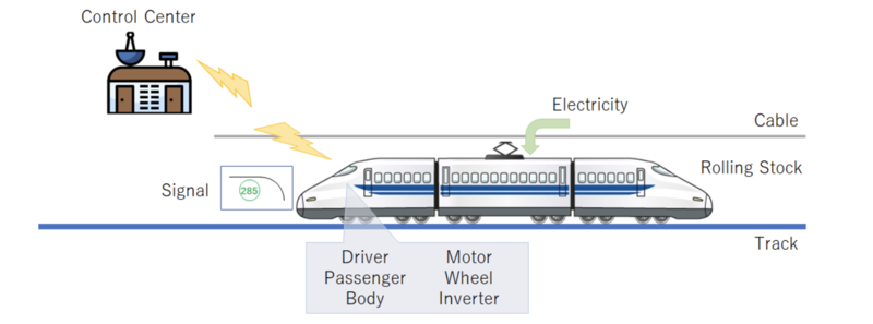
High-Speed Rail is a type of passenger rail transportation system that operates at high-speed with high voltage electricity. With respect for the multiple definitions for high-speed rail, the International Union of Railways defines high-speed rail as systems of rolling stock and infrastructure which regularly operate at or above 250 km/h on new tracks, or 200 km/h on existing tracks. Figure 8, above, shows the basic components of high-speed rail system. Rolling stock that obtain electricity from cable (as shown, or ground-based rail) as a power is operated by a driver who follows signals and communicates with one or more control centers. The dedicated or specifically upgraded tracks guide the train.
DSM Allocation
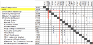
The DSM shows that the 2HSR is part of the mass transportation system in large context. It requires 3TVT Train Vehicle Technology, 3ELM Electricity Management, 3STM Structure Management, and 3TCS Traffic Control System. In addition, these level 3 technologies require level 4 technologies that are consist of 4 DRS Driving System of the vehicle such as motor, 4VHB Body of vehicles, 4CTS control system of the vehicle, 4PWG power generator or power plant of electricity, 4HVT technology for transmitting high voltage electricity, 4CIV converter and inverter inside the vehicle, 4TRF transforming electricity to appropriate voltage, 4TRM maintenance of tracks, 4CES maintenance of civil engineering structures such as bridges and tunnels, 4PRC route control system, 4EDP data processing unit, 4MAC technology for monitoring and communicating data.
Roadmap Model using OPM
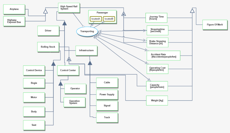
The OPM describes the decomposition and primary function of HSR system. The level 1 decomposition of the system is Driver, Rolling Stock, Control Center and Infrastructure. Rolling Stock consists of physical components such as bogie and body. The main components of control center are Operator and Operation system that support drivers by providing information from several data sources and calculating the signal pattern. Infrastructure, such as tracks and signals, is the foundation of the system that physically and electrically support the operation.
Figures of Merit
| Figure of Merit | Units | Description |
|---|---|---|
| Journey time = Distance/v_max | hour | Duration of transporting location A to B. Certain distance divided by speed |
| Stopping time | seconds | The time between when an event is detected and when a vehicle stops |
| Accident rate | # accidents/people | Number of accidents divided by cumulative transportation amount |
| Weight | kg | Weight of train |
| Brake stopping distance | m | Distance that it takes to come to a complete stop |
| Capacity | people/train | Number of passengers carried by train |
| Operating Cost | $/people/km | Operating cost per people times distance |
The journey time TJ is the duration of transporting from location A to location B. By omitting the acceleration and deceleration near location A and B, TJ can be calculated using v_max as TJ = D/v_max, where D is the distance between location A and B and v_max is the maximum speed of the high-speed train. Considering the equilibrium state that the propelling force is equal to resisting forces, that is,
Here, η is the energy conversion ratio of motors, N is the number of motor cars, P[W] is the power of a motor, m[kg] is the mass of the train, C_d is drag coefficient, A [m^2] is reference area, ρ [kg/m^3] is density of air, and α and β [s/m] are empirical numbers from experimental results, while there are a lot of variations on parametrizing the kinematic resistance.
Stopping time can be broken down into three parts:
- Detection time: T1-T0,
- Reaction time: T2-T1,
- Braking time: T3-T2,
where T0 is the time when an obstacle enters the train’s path, T1 is the time when the obstacle is detected, T2 is the time when the train starts braking, and T3 is the time when the train finally stops.
The detection time and the reaction time are strongly related to railway traffic operation. Let us consider that an operator in the traffic control center finds an obstacle on the railroad, for example via video cameras. In this case, the detection time will be about two seconds. After his/her detection, he/she notifies the driver to engage an emergently stop of the train via a wireless network, which takes another two seconds or more. Finally, the driver engages the train’s emergency brakes after yet another two seconds or more. In the system described, starting to decelerate the train takes six seconds or more, which can be crucial because in six seconds the train will travel 500 meters when the speed of the train is 300km/hour. These detection and reaction times can be improved by camera detection technologies and by ATS (automatic train stop), which are not the focus of this report.
Calculating the braking time: given the maximum value of friction between a vehicle and track is static friction, the braking time can be calculated by solving the equation of motion,
Here, m is the mass of the train, v is the velocity of the train, μ(v) is adhesion coefficient, and d [km/h] and c [km/h] are empirical numbers from experimental results on the Shinkansen, Japan, while the other high-speed rails have similar formulas with slightly different values for parameters[3]. If braking time T3-T2 is T, then T is described as the following equation:
The above formula can be calculated by numerical integration.
Note that the above equation does not consider the limitation of the magnitude of deceleration, which comes from the need to keep safe passengers on board. For example, if the deceleration is huge, such as 8G, all the passengers will be killed by this deceleration. According to Powell and Palacin, passengers become uncomfortable and have difficulty holding on while standing when the deceleration is larger than 1.5 m/s^2, and the passengers cannot keep their seats when the deceleration is larger than 2.5 m/s^2.
Alignment with Company Strategic Drivers
Strategic Driver: To develop a safe, comfortable, and punctual high-speed train system that can stop as quickly as possible to minimize the possibility of collision and derailment.
Alignment and Targets: The HSR Technology Roadmap will target a dedicated track-guided system with powerful brake that can decelerate at 1.5m/s^2 and an obstacle sensor system that can detect and respond to any dangerous obstacle immediately. This driver is currently aligned with the HSR technology roadmap.
The continuous goal for the railway business is to develop a safe and convenient train system that is attractive to potential passengers. In the context of safety, the braking time should be as short as possible without injuring passengers due to a too intense jerk (jerk is the derivative of acceleration). The simplest way to reduce the braking time is to reduce speed. This approach is accepted by passengers when the train is traveling under bad conditions, such as heavy rain or mechanical troubles. Also, the total weight (vehicle weight + passengers’ weight) of the train would affect the braking time. In this context, reducing capacity would contribute to reduced braking time. However, operating at reduced profitability and efficiency, by reducing operational speed and capacity, would negatively affect the attractiveness of the system to passengers.
Positioning of Company vs. Competition
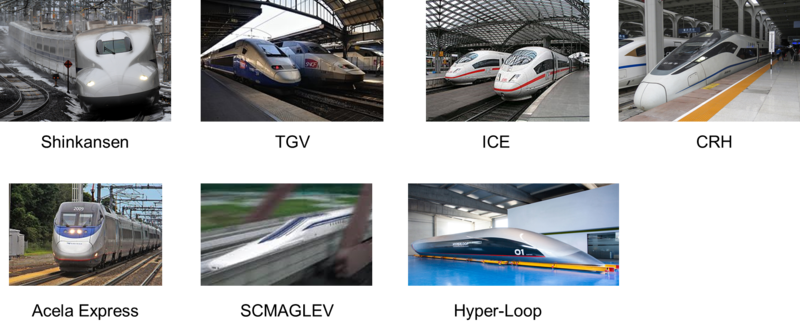
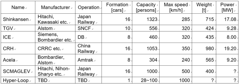
The figure below shows a summary of several types of high-speed rail systems, derived from public data. The Shinkansen in Japan has the largest capacity in the world and these trains are formally operated at a fixed number of cars. In Europe and China, the number of cars can change flexibly based on regions’ needs and the types of models. This flexibility better supports variabilities in demand but affects the operating cost and makes driving the vehicle more difficult. Typically, operational speed is capped by sharpness of curves and the strength of track components and infrastructure. China Railway has the highest operational speed supported by newer track and infrastructure and fewer sharp curves. However, unconventional systems such as maglev and hyper-loop, using totally different propulsion and guiding systems, enables trains to be operated at much higher speeds. The SCMaglev is now under construction in Japan and operating in test mode, while Hyper-loop systems are still in a concept phase and need further development to their core system. The table below also shows that the Acela Express is less efficient compared to other high-speed rail systems, with lower speed, less capacity, and heavier vehicles.
Technical Model
Table below shows the morphological matrix of the main technological decision variables on high-speed rail that would affect breaking system and safety. Five conventional railway systems (Blue:Shinkansen, Red:TGV, Green:ICE, Orange:CRH, Purple:Acela) are plotted on the matrix. Note that the architecture of the motor is different between TGV/Acela and others. These two trains are push-pull, with locomotives at both ends of the train, which has the advantage of flexibility in the number of cars between the locomotives and interoperability with local tracks. However, this configuration has a disadvantage with efficient braking because less motors acting on less axles are available to electrically deaccelerate the vehicle. The shape of the front affects air drag and noise when running at high speed. The Shinkansen is shaped carefully so that it can minimize noise that would adversely impact urban areas and going through tunnels. JR East is trying to develop air flaps that can increase air drag as part of emergency braking systems. To minimize weight, most rail systems use aluminum because it is light and easy to handle. Some companies are exploring the use of alloyed magnesium or carbon-fiber for the car body, but these technologies are not yet in production. The most popular electric system for High-Speed Rail is 25 kV AC nowadays since it has an advantage in carrying large amounts of electricity.
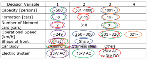 (Blue:Shinkansen, Red:TGV, Green:ICE, Orange:CRH, Purple:Acela)
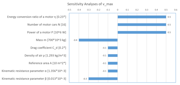
The typical values of the above parameters in Shinkansen N700 Series (v_max = 285 km/hour) and their sensitivities are shown in the following diagram. The values in the square brackets mean the values of N700, while the asterisks mean assumed values. η and P have the same positive sensitivity to v_max, but if P is increased the motors usually weigh more, which causes the increase of the mass which has negative sensitivity, resulting that P has relatively weak sensitivity to v_max.
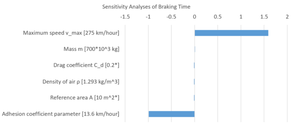
The sensitivity of the braking time of Shinkansen N700 Series is shown in the following figure, while the values in the square brackets mean the values of N700 and the asterisks mean assumed values. The sensitivity of d is the largest other than v_max. Although d is an empirical constant, d is one of the key parameters to reduce the braking time. Actually, several researches, such as [5], have been done to increase d by controlling the brakes more effectively and by injecting ceramic particles, and these also mentioned the increase of air drag by additional fins has only a small contribution to reducing the braking distance, which is consistent with our analysis that the sensitivities of C_d and A are much smaller than d.
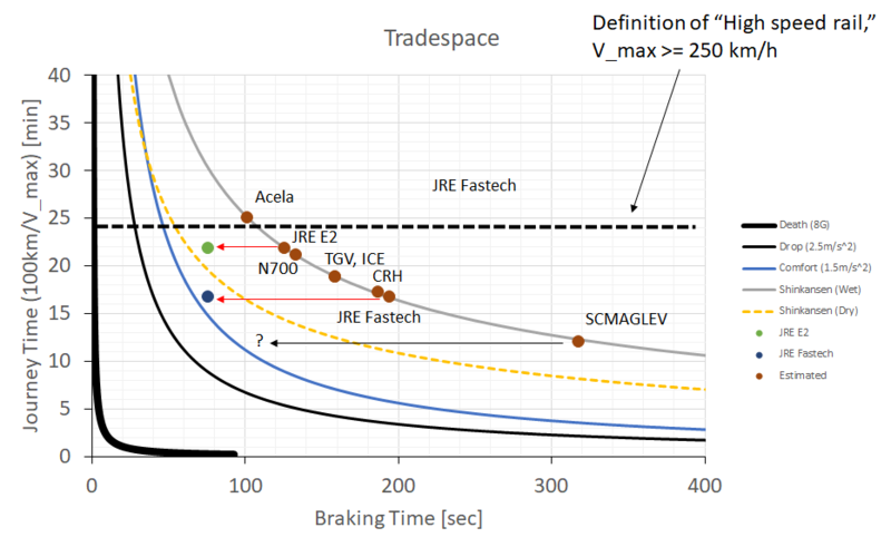
Figure below shows the tradespace between journey time and braking time. Note that the definition of “High Speed Rail” is that the maximum sustained speed of a train in service is over 250 km/hour, which is shown as the black dotted line. In addition to the frontiers of Shinkansen JRE2 in both wet (solid line) and dry (dashed line) conditions, the frontier in 8G deceleration (Death), one where passengers cannot keep their seats (Drop), and one in comfort situation (Comfort), that is, the passengers are able to hold on or remain seated as the train decelerates. Also, the estimated values of braking time and journey time of several high-speed trains, whose characteristics are shown in Table 4-3, are plotted under the condition that all the parameters except for mass and the maximum velocity are the same. For JRE E2 and JRE Fastech, the values written in [5] are also plotted as red circle and blue circle, respectively, to compare the actual values and the estimated values.
Calculations reveal that, even when the weather is dry, the deceleration due to the adhesion friction is low enough that passengers can keep their seat with comfort. As the actual values of JRE E2 and JRE Fastech are closer to the “Comfort” curve, recent research has enabled more efficient braking to reduce the braking time.
The SCMAGLEV is propelled by electromagnetic force, not by friction between the vehicle and the rail. This difference is indicated by unique behavior in the tradespace. The SCMAGLEV has potential to decelerate hard enough to drop passengers from their seats, which means SCMAGLEV theoretically can operate beyond the “Drop” curve. However, from the viewpoint of passengers’ safety, it cannot go beyond “Drop” curve unless restraints or other instruments are installed to keep the passengers in their seats during emergency braking.
Financial Model
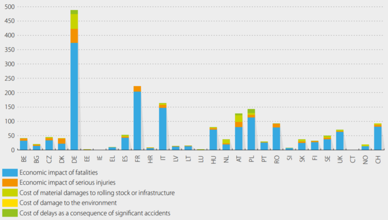
At first glance, improving safety does not necessarily seem to improve revenues or profitability of railway systems. However, as shown in figure 3a-1, below, the cost of accidents is financially expensive and damages the system operator’s reputation, reducing future revenue. Long term continuous improvements in safety systems and technology is crucial for maintaining the safety level of facilities and building the safety culture of the organization. In addition, some safety components improve the service quality of the system, which helps to increase revenues. In most countries, increasing the operating speed of trains requires qualification inspections, which are regulated by public authorities. For example, the Japanese practice a general principle that an increase in operational speed should not affect safety or environmental quality: longer required braking distance and higher noise level due to increased speed are limited by policy. Even if the vehicle can attain a higher speed, they cannot be operated commercially until verified that the system has the same safety performance and environmental quality. As a result, railway companies often consider brake system improvements and increasing speed as a set.
Economic impact of significant railway accidents, by country in SERA, million EUR, 2016. (Source: ERAIL, Report on Railway Safety and Interoperability in the EU 2018)
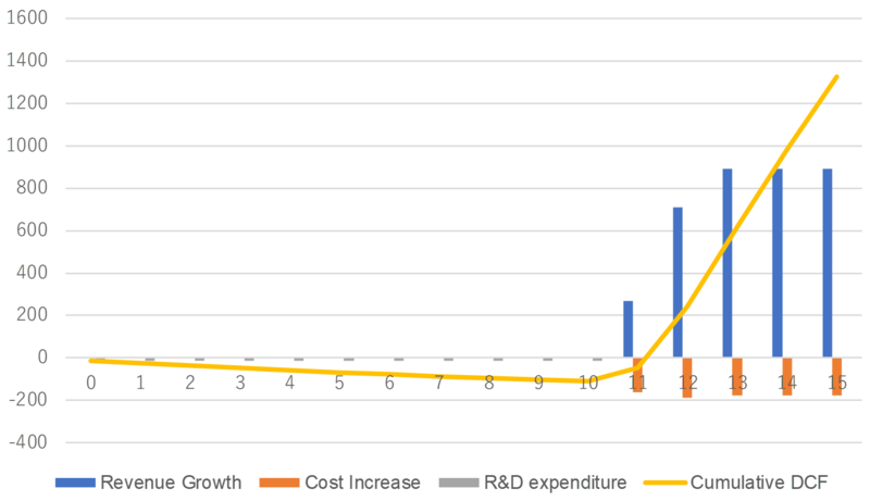
To build a financial model, we assumed increasing operational speed would increase revenues by taking market share from the airline industry and stimulating demand for traveling. As described above, increasing operational speed requires improved systems to maintain stopping distance. To estimate the amount of revenue growth attributable to increased operating speed we used financial data from Central Japan Railway (CJR) from FY2013~2016. During this period CJR increased the operational speed from 270km/h to 285km/h, which also incurred higher costs for maintaining facilities and extra energy consumption. The R&D expenditure total is estimated based on the report by the Railway Technical Research Institute in Japan and the assumption that the research would be split proportionally across projects within the railway company. The table also includes the discount rate, assumed as 5%, and Net Present Value (NPV) for this research. In addition, we assumed that the research started in the year when the previous speed increase project was completed, 2003, and ran for ten years. The manufacturing cost is not considered in this model because the timing of introducing a new vehicle is based on replacement of deteriorated vehicles and component upgrades may be part of regular service intervals. The model shows that the R&D expenditures for improving braking systems and other related components can have sufficient Return on Investment (ROI) in just a few years. While the increase in revenue from 2015 is caused by several factors such as business conditions and other system upgrades, improving certain safety related components is a worthwhile investment if grouped with other components to, in this case, increase operational speed.
(Source: For Revenue and Operational cost, referred CJR annual report FY2013~2016)
NPV analysis for improving braking system and increased operational speed
List of R&T projects and Prototypes
Stopping time is the key FOM for high-speed rail safety. Stopping time can be broken down into three technological areas:
- Detection time
- Reaction time
- Braking time.
Investments in these three areas should be directed to reduce time lag in each and lag across the system.
Detection Time and Reaction Time
Detection time is defined as the time between when an obstacle enters a train’s path and when the obstacle is identified as an obstacle that could endanger the train (or people or property near or in the path of the train). Reaction time is defined as the time between when the endangering obstacle is identified as an issue and when the train’s brakes are activated. Decreasing these times reduces the risk of trains colliding with an obstacle. Currently, the detection time and reaction time take more than six seconds, while the braking time takes more than eighty seconds, depending on the maximum speed of a train. Three technology upgrade options reduce these times:
- Monitoring systems that allow the driver to see further ahead than line of sight
- Automatic detection systems to recognize objects with specific properties, such as size or shape
- Automatic systems that actuate braking systems without requiring specific action from the driver.
The first option introduces a monitoring system to check for obstacles. Currently, the detection is made by the driver, or, on some lines, by field staff or maintenance workers at specific locations, such as stations. Detection by the driver is not effective at high speeds due to reduced lines of sight relative to the speed of the train and the long distance traveled in the short time the driver needs to determine if action is required. To improve the driver’s ability to see further, fixed video cameras can be deployed along the railroad to monitor the entire rail system. Because of the expense of this solution, cameras would likely be deployed in phases, starting by choosing the most dangerous points to maximize the early investment. Another way to improve the driver’s ability to see further could be to deploy unmanned vehicles, such as drones, to monitor the tracks ahead of the train. This method is works only when the route includes no tunnels, but it could be more cost-effective than using fixed cameras. Depending on the rail operator, this system will need fifteen to twenty years to go into production. The second option introduces an automatic detection system to automatically identify any dangerous obstacles captured by the monitoring system, to reduce the reaction time of a driver. This option can be achieved by leveraging existing image detection and analyses technologies, which would be much less expensive than the first option. This option would take about five years to bring into production. The third option introduces an interface between the automatic detection system and the braking system. When the system detects a dangerous situation ahead of the train, such as an object on the tracks, it would automatically actuate the emergency brakes. This integration would require upgrading all the existing vehicles, adding electrical connections between the new braking system and the existing braking system, taking about ten years to bring into production.
Braking time
Improving braking time will have the largest impact on reducing the entire stopping time. Based on previous analyses, three options reduce the braking time:
- Increase the adhesion coefficient between the wheels and the track rails
- Reduce the mass of a vehicle
- Increase the reference section against air.
Research results by Arai, et al. [1] can be applied to increase the adhesion coefficient by spraying specific polymers between the train wheels and the track, development of which would take about five years. Mass reduction can be achieved with further improvements to bodies and motors, which would take about ten years. Increasing the reference section was also researched by Arai, et al, which can be brought to production within about ten years. Unfortunately, minimal stopping time is limited by passenger capabilities [2]. A “Comfort” deceleration rate of 1.5 m/s^2 allows passengers who are standing to hang on – above this deceleration rate passengers may not have the hand strength to maintain a grip on a hand hold. A “Drop” deceleration rate of greater than 2.5 m/s^2 will cause passengers to drop out of their seats.
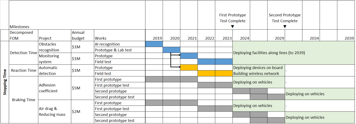
The Gantt chart of R&D investments and their deployments are shown below. The large part of R&D investment, $5MM per year, will be on the improvement of the adhesion coefficient between a train and a rail, while investment in obstacle detection and monitoring/automatic reaction systems will continue in the next 5 years. (Note that the scale of the calendar changes after 2024 from 1 year/column to 2.5 years/column.)
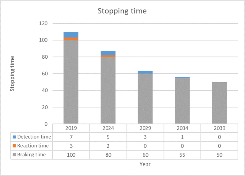
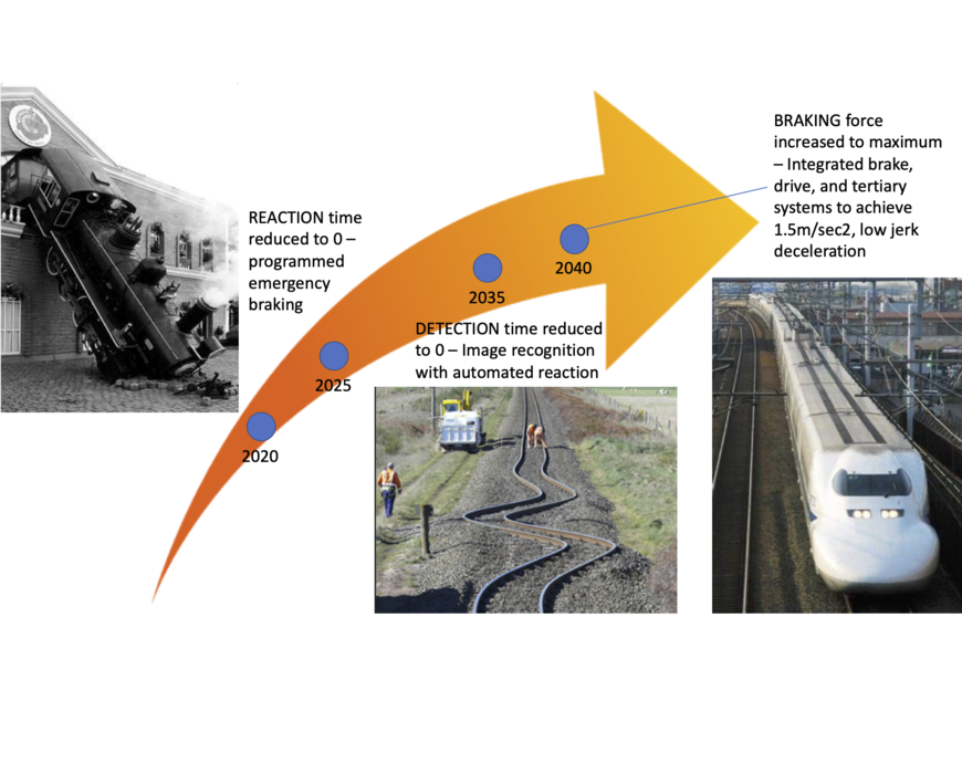
The following chart shows the goal value of each time by the R&D investments and deployments of the resulted techniques. The reduction of detection time would be gradually achieved because massive investment will be needed. Reaction time could be reduced in ten years by the automatic braking system. The improvement of braking time could be done by leveraging existing research results, while “Comfort” deceleration rate (1.5 m/s^2) and “Drop” deceleration rate (2.5 m/s^2) could be the hard wall to improved braking time, which would result in slow improvement (from 2029 in this table).
The future improvement of estimated stopping time of Shinkansen (N700) by progressing several options.
References
[1] H. Arai, S. Kanno, N. Yanase, Brake System for Shinkansen Speed Increase, JR EAST Technical Review, No.12, 2008. https://www.jreast.co.jp/e/development/tech/contents12.html
[2] J. P. Powell, R. Palacin, Passenger Stability Within Moving Railway Vehicles: Limits on Maximum Longitudinal Acceleration, NewRail - Centre for Railway Research, Newcastle University, 14 August 2015
[3] UKEssays. The Anglo French Concorde Project [Internet]. November 2018. [Accessed 14 November 2019]; Available from: https://www.ukessays.com/essays/management/development-of-the-anglo-french-concorde-project-management-essay.php?vref=1.
[4] Wikipedia, Tupolev Tu-144 (Last edit 3 Nov 2019), https://en.wikipedia.org/wiki/Tupolev_Tu-144
[5] Wikipedia, Concorde (Last edit 31 Oct 2019), https://en.wikipedia.org/wiki/Concorde
Keys Publications and Patents
The following papers and patents were reviewed:
Anti-derailment
- US Patent 2,800,861, Anti-derailing device, Joseph Michalski, Vestaberg, PA, 30 July 1957
- US Patent 3,084,637, Safety Derail Preventer, Frank W. Kohout, Pacific Palisades, CA, 9 April 1963
- Nicholas Wilson, Robert Fries, Matthew Witte, Andreas Haigermoser, Mikael Wrang, Jerry Evans, and Anna Orlova (2011) Assessment of safety against derailment using simulations and vehicle acceptance tests: a worldwide comparison of state-of-the-art assessment methods, Vehicle System Dynamics, 49:7, 1113-1157
- Jing Zeng & Qing Hua Guan (2008) Study on flange climb derailment criteria of a railway wheelset, Vehicle System Dynamics, 46:3, 239-251
Object detection
- US Patent 5,787,369, Object Detection System and Method for Railways, Theodore F. Knaak, Orlando, FL, 28 July 1998
- US Patent 5,978,718, Rail Vision System, Westinghouse Air Brake Co., Wilmerding, PA, 2 November 1999
- US Patent Application 10/251,422, Railway Obstacle Detection System and Method, James R. Jamieson, Savage, MN and Mark D. Ray, Burnsvile, MN, 20 September 2002
- Yong-Ren Pu, Li-Wei Chen, and Su-Hsing Lee, Study of Moving Obstacle Detection at Railway Crossing by Machine Vision, Information Technology Journal 13 (16) 2611-2618, (2014)
Track condition
- P.A. Costa, A. Colaço, R. Calçada, A.S. Cardoso, Critical speed of railway tracks. detailed and simplified approaches, (2014)
- Ali Al-Shaer, Denis Duhamel, Karam Sab, Gilles Forêt, Laurent Schmitt. Experimental settlement and dynamic behavior of a portion of ballasted railway track under high speed trains. Journal of Sound and Vibration, Elsevier, 2008, 316, pp.211-233. 10.1016/j.jsv.2008.02.055
- J. P. Powell, R. Palacin, Passenger Stability Within Moving Railway Vehicles: Limits on Maximum Longitudinal Acceleration, NewRail - Centre for Railway Research, Newcastle University, 14 August 2015
Braking
- Lionginas Liudvinavičius & Leonas Povilas Lingaitis (2007) Electrodynamic braking in high‐speed rail transport, Transport, 22:3, 178-186
- Jie Liu, Yan-Fu Li, Enrico Zio, A SVM framework for fault detection of the braking system in a high speed train, Mechanical Systems and Signal Processing 87 (2017) 401–409
- Hiroshi Arai, Satoru Kanno, Naohito Yanase (ND), Special Edition Paper – Brake System for Shinkansen Speed Increase, JR EAST Technical Review-No.12 PP12-15, https://www.jreast.co.jp › development › tech › pdf_12
- Piers Connor (2014), High Speed Railway Capacity – Understanding the factors affecting capacity limits for a high speed railway, 1964-2014 High Speed Rail: Celebrating Ambition. University of Birmingham, 8-10 December 2014, http://www.railway-technical.com/books-papers--articles/high-speed-railway-capacity.pdf
- David Barney, David Haley and George Nikandros, Calculating Train Braking Distance, Signal and Operational Systems, Queensland Rail (Copyright © 2001, Australian Computer Society, Inc. This paper appeared at the 6th Australian Workshop on Safety Critical Systems and Software (SCS’01), Brisbane. Conferences in Research and Practice in Information Technology, Vol. 3. P. Lindsay)
The Japanese high-speed rail tracks are isolated through elevation or fencing such that many potential obstructions are avoided. However, the tracks are still subject to earthquakes and the potential for large objects such as trees to be blown onto the tracks. Other country’s tracks are not as well protected, and as high-speed rail is adopted in countries with much longer distances to travel the cost to isolate the tracks may prove to be prohibitive. As such, other safety systems will be needed to keep passengers, communities, and rail rolling stock safe.
Anti-derailment
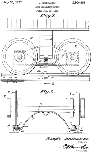
Anti-derailment systems come in several forms. Systems for low-speed use included additional hardware to stop the wheels from jumping the track and to keep the wheels close to the track once derailed. The image to the right, from US patent 2800861, renders one such system; US patent 3984637 specified the use of additional safety guide rails that are not load bearing. Later systems included improved wheel flange design to avoid the wheel riding up on the flange in curves. Improvements to truck (bogie) designs and couplers reduced tolerances in severe braking as well as reducing sway at high speed.
Modern high speed rail designs typically include simulation tools to detect potential design issues that might cause instability at high speed. These tools are detailed in Nicholas Wilson, Robert Fries, Matthew Witte, Andreas Haigermoser, Mikael Wrang, Jerry Evans, and Anna Orlova (2011) "Assessment of safety against derailment using simulations and vehicle acceptance tests: a worldwide comparison of state-of-the-art assessment methods, Vehicle System Dynamics," 49:7, 1113-1157, DOI: 10.1080/00423114.2011.586706 from the International Journal of Vehicle Mechanics and mobility. This paper details mathematical models used to simulate vehicle resonant response and instability:
- vehicle overturning
- poor load equalization
- flange climbing
- excessive track forces, including gauge spreading, rail rollover, and track panel shift
- longitudinal train forces
The paper reviews the state-of-the-art methods for derailment safety assessment for the following countries and regions:
- European Union (EU, excluding the UK but including Switzerland and Norway)
- UK
- China
- South Korea
- Japan
- USA
- Russia and the Commonwealth of Independent States (CIS)
Many countries are moving away from physical testing facilities, which are typically long lengths of track with particular tests built in such as sharp curves and other potentially dangerous conditions, towards computer simulation, which can cover many more potential conditions at substantially reduced costs. At issue is the level of accuracy of the simulations and how to test if the simulations are representative of real life conditions. However, national safety standards are incorporating simulation as an acceptable test mechanism, proving simulation's growing acceptance with both engineers and safety administrators.
Object detection
The original track detection systems were humans observing conditions and then operating signals so that one train operator would know how far ahead the next train was. For the last twenty-five years modern safety systems for detecting track obstructions include camera and other optical systems to detect objects on the track ahead of the train. Some of these systems are train mounted, using lasers and detectors for range finding and including reflective components to allow these systems to detect objects not in straight line of sight of the train. Patent application US2004/0056182 A1 by Jamieson et al. describes on such system, a laser-based system with scanning lasers and receivers. The received echos from the lasers are then interpreted to determine if an object is obstructing the tracks.
Other systems include track-side cameras and pattern detection and are becoming increasingly common to flag potential obstructions. State of the art systems include automatic detection and activation of brakes. The SCMAGLEV has no on-board operator; presumably while humans control the train remotely many of the emergency detection systems are partially or fully automated.
Track condition
The design of the track has itself been adapted to support high speed rail. Superior rail, track, and bed design and implementation respond to the increased longitudinal and latitudinal forces on the rails and these forces’ transfer through the ties and into the ballast and bed. The ability of the rails to withstand the extended braking force of a high-speed train coming to an emergency stop has been researched and modeled to ensure that the tracks do not distort under extreme loads.
P.A. Costa, A. Colaço, R. Calçada, A.S. Cardoso, "Critical speed of railway tracks. detailed and simplified approaches," (2014), doi: http://dx.doi.org/10.1016/j.trgeo.2014.09.003 details a simplified approach to modeling track embankments and compares this method to computationally complex methods. At issue is that the dynamic loads of high speed trains put much higher loads on the elastic components of the track system, potentially distorting track system components beyond tolerances, causing derailment.
Jing Zeng & Qing Hua Guan (2008) "Study on flange climb derailment criteria of a railway wheelset, Vehicle System Dynamics," 46:3, 239-251, DOI: 10.1080/00423110701313989 details how the form of the wheel flange needs to be different at higher speeds to avoid the wheel climbing onto the flange while moving through a curve. From this paper: "Based on the Coulomb’s friction law and the creep force laws, the Friction Formula and Creep Formula for the evaluation of derailment are derived, respectively. The analysis shows that the derailment coefficients of Friction Formula and Creep Formula required for derailment are increased considerably for smaller and negative yaw angles, and tend to the value of Nadal’s Formula at larger wheelset yaw angles."
Braking
Brake system design is the most critical issue for emergency braking right now. Converting the kinetic energy of a heavy and fast moving train to heat and then dissipating that heat is the current limiting factor for stopping distance. Disk brakes, as found under the Acela and other trains, is now considered state of the art. Load balancing systems are also deployed to avoid derailment while maximizing brake application when the back of the train is heavier than the front. Overall braking performance may be improved with driveline design changes, for example the Shinkansen has each axle powered, offering the opportunity to use the motors to further apply substantial decelerating forces to the wheels. By comparison, the Acela has a leading and trailing locomotive, with the passenger rolling stock left with wheel brakes only.
Beyond the details of the functioning of the brake systems, research has also been done on how people tolerate lateral acceleration during breaking. J. P. Powell, R. Palacin, "Passenger Stability Within Moving Railway Vehicles: Limits on Maximum Longitudinal Acceleration," Urban Rail Transit, 2015-06-01, 10.1007/s40864-015-0012-y studied human reaction to the derivative of acceleration, the jerk, and determined that passengers could tolerate higher lateral acceleration if it is ramped up instead of being applied quickly. This research will have implications in how to tune automation in the application of brake systems to increase passenger safety while also reducing overall braking distance.
Research Summary
Modern high speed rail has pushed the maturation of technology for extended object detection, track quality, and stability. Currently braking is limited by brake system capability. Based on the research completed for this project, it is our opinion that once braking effectiveness is achieved, the limiting factor will be passenger safety – slowing the train too rapidly with unrestrained passengers will cause more injuries that it might save. However, with the acceptance of passenger restraints this cycle of object detection, track quality, stability, and braking could begin again.
Technology Strategy Statement
High speed rail delivers on two promises:
1. Minimize time to destination
2. Maximize safety when in motion
The goal of the below proposed technology improvements is to maintain the safety margins specified by regulations while decreasing time to destination. As high speed trains are a mature technology, the proposals below are about optimization. The expectations for these optimizations are incremental increases in top speed, which the motor systems and surrounding infrastructure are already capable of handling.
Increases in high speed rail top speeds are currently limited by policies in most regions, dictating maximum stopping distances. These maximum distances, combined with the human factor of hand strength, create a maximum speed above which the train cannot stop in the distance allotted and below the deceleration rates that will keep passengers safe. However, several opportunities offer some room for increasing speed. Currently, the process of determining if the emergency brakes should be applied can take up to six seconds. Improvements that allow the driver to see further down the tracks and to more quickly understand what is being seen offer opportunities to shave off precious seconds. The mechanics of the braking systems, from wheel brakes to other devices to put drag on forward motion, such as using the motor systems or including air foils, still have room for improvement. Pursuing all of these options will yield benefit. Each must be considered in the context of potential secondary gains – would improved braking mitigate more risk than improved detection or recognition systems? These secondary gains are likely to vary from one rail system to another as conditions and context varies, as well as differences in tolerance for certain kinds of risk by each society sponsoring these systems. Changes in passenger expectations and rail service policies may also provide additional room for speed increases. For example, train policies could include that walking about in the train is permitted only for specific reasons and maybe only at specific times to allow for harder deceleration. Seat belts or other restraints could also offer higher speeds with passenger safety retained under still harder deceleration. The desire to shorten trip duration will continue to drive innovation beyond the scope of this road map.
Critical Values in Technology
| Property | Value | Units | Notes |
|---|---|---|---|
| Max Stopping Distance | 4000 | Meters | Japan, others similar |
| Acceleration | 1.5 | M/sec^2 | Cruise to stop |
| Jerk | (curve) | M/sec^3 | See note below |
| Reaction time | Minimize | Seconds | Time between situation recognition and start of braking |
| Repeat delay | 0 | Seconds | Time between one brake application and the next |
| Cruise Speed | Maximize | Km/hr |
Note that the Jerk is not a single number but a curve that needs to be optimized for the comfort of the population served. Current braking technology may require the jerk to be controlled through the motor system to create an acceptably smooth application.
Note that the actual repeat delay may be substantial as the time for the train to resume to maximum cruise speed may be long enough for the brakes to cool. However, not considered here is whether the train, once stopped, will need to allow the brakes to cool sufficiently so that if needed the train can stop from a lower speed that would take less time to achieve.
Technology Prioritization for Japanese High Speed Rail
| Technology | Priority | Time (Years) | Notes |
|---|---|---|---|
| Detection time | 1 | 15 | Will improve slowly over time as image recognition improves |
| Reaction time | 2 | 5 | Integration of AI with hardware controls |
| Braking | 3 | 20 | Includes improved materials, integration of motor systems for braking, and other systems e.g.: air foils |
Improving detection and reaction time offers an easy win as the time to detect an issue is when the train is moving fastest. For the Shinkansen, currently reaction times are over six seconds, which means that the train travels over 470m before applying the brakes or over 12% of its total allotted stopping distance. To drive the sum of these times to zero means that the public must accept the risk of a false positive identification of an issue and that a driver may cancel a false positive after the train has started its emergency braking process.
Improving the braking capacity of a train will require several technologies to be developed and others to be improved. To create a smooth transition to hard braking the motor control systems must be changed to include this capability and application of motor control followed by hard braking needs to be handled by machines, not a human driver, to maximize braking performance. These motor modifications may or may not be possible on trains with dedicated locomotives. On trains with all axles powered this control becomes more complex as the power needs to be balanced by weight but may be ultimately easier to accomplish because of the lower stress on each motor system.
Other high speed rail systems may have different priorities based on what is currently limiting their top speeds. For example, the Acela is currently limited by the condition of the tracks and in Connecticut by regulation due to Connecticut's many grade-level crossings. As stated above, some drive systems may not have the capacity to significantly assist the braking system in slowing the train and these drive systems may or may not be amenable to automation to improve braking application. These hardware differences may shift the priorities as stated above.
The population profile using these systems may also impact the safety standards. Assuming that a typical adult has the same hand strength, an adult population that is average over 100kg may need slower acceleration that a population with an average weight two thirds of that population. The heavier passengers may not be able to maintain grip on the hand holds during emergency braking. Other factors yet to be imagined will come into play as high speed trains are deployed into new regions with different topography, culture, and needs.
