Difference between revisions of "Mining the Martian Surface for in Situ Resources"
| (104 intermediate revisions by 4 users not shown) | |||
| Line 3: | Line 3: | ||
The technology roadmap identifier: | The technology roadmap identifier: | ||
* '''3MIM - Mars In Situ Mining''' | * '''3MIM - Mars In Situ Mining''' | ||
The number 3 denotes that this roadmap | The number 3 denotes that this is a Level 3 technology roadmap at the subsystem level. A Level 1 would indicate a market level roadmap, Level 2 would be at the product level, and Level 4 at the component level. In reference to our technology, Level 1 would describe the entire system required to mine, filter, and store resources on Mars. Level 2 describes an autonomous mining vehicle, and the sub-system (Level 3) of excavation is defined in this roadmap. A Level 4 technology would consist of a sub-component of the excavation subsystem, such as the drill bit. | ||
==Roadmap Overview== | ==Roadmap Overview== | ||
Copious resources to construct habitats and sustain life support on Mars are required for long-term manned missions to the "Red Planet". The current state of technology requires that all resources for human survival on Mars must be brought with astronauts or sent from Earth prior to the crew's arrival. However, limitations presented by the cost of sending cargo and mass-launch capabilities of current propulsion would prevent any manned Mars mission to be fully sustained by terrestrial resources. One way to solve this discrepancy is to send technology and machinery to Mars to generate vital resources in situ, or with local materials, prior to human arrival. One vital resource required for human life support will be an ample supply of water. This roadmap focuses on the autonomous mining excavation technology required to accrue water on Mars. | |||
The Mars In Situ Mining extraction technology would fall under the matter transporting category of the functional taxonomy. We model our extraction technology on the extraction architecture deemed the most successful by Honey Bee Robotics’ most recent experiments on Planetary Volatile Extraction (PVEx). The extraction technology they deemed the most efficient approach in terms of both water extraction and energy consumption is referred to as the “corer” and takes the form of a dual wall coring auger. | The Mars In Situ Mining extraction technology would fall under the matter transporting category of the functional technology taxonomy. We model our extraction technology on the extraction architecture deemed the most successful by Honey Bee Robotics’ most recent experiments on Planetary Volatile Extraction (PVEx). The extraction technology they deemed the most efficient approach in terms of both water extraction and energy consumption is referred to as the “corer” and takes the form of a dual wall coring auger. | ||
[[File:MarsMiningVehicle.png|500x500px|frameless|center]] | [[File:MarsMiningVehicle.png|500x500px|frameless|center]] | ||
[[Category:1M]] | |||
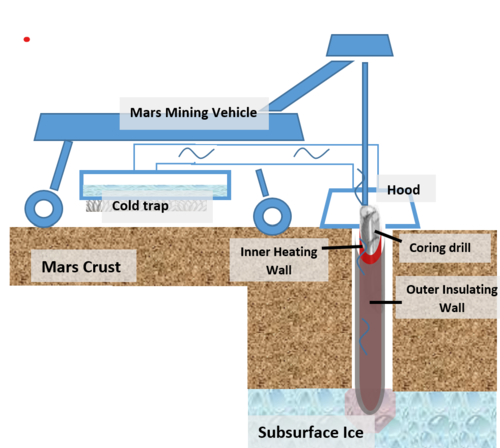
'''Figure 1 ''' - Mars In Situ Mining Extraction Technology | '''Figure 1 ''' - Mars In Situ Mining Extraction Technology | ||
| Line 28: | Line 28: | ||
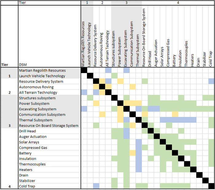
Below is the DSM Allocation for the interdependencies of the the systems and subsystems related to the technology roadmap. This diagram corresponds to the hierarchy tree in Figure 2. The extraction technology has numerous co-dependencies of systems, subsystems, and components. This will be further investigated to better understand the performance and timeline tradeoffs for the technology roadmap. | Below is the DSM Allocation for the interdependencies of the the systems and subsystems related to the technology roadmap. This diagram corresponds to the hierarchy tree in Figure 2. The extraction technology has numerous co-dependencies of systems, subsystems, and components. This will be further investigated to better understand the performance and timeline tradeoffs for the technology roadmap. | ||
[[File: | [[File:DSMminingmarspart2.png|700x700px|center|frameless]] | ||
'''Figure 3 ''' - DSM Martian Mining Technology Roadmap | '''Figure 3 ''' - DSM Martian Mining Technology Roadmap | ||
Key: | |||
Green boxes represent a physical interaction | |||
Blue boxes represent an environmental interaction | |||
Yellow boxes represent a digital interaction | |||
==Roadmap Model using Object-Process-Methodology (OPM) == | ==Roadmap Model using Object-Process-Methodology (OPM) == | ||
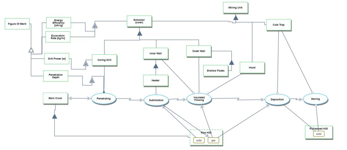
We created an Object-Process-Diagram (OPD) of the Mars In Situ Mining Extraction Technology below in Figure 4. The diagram serves to capture the main object of the roadmap, the corer, its decomposition into sub-components (coring drill, inner wall, outer wall), its characterization by Figures of Merit (FOMs) and the main processes of the system (Drilling, Heating, etc.). | We created an Object-Process-Diagram (OPD) of the Mars In Situ Mining Extraction Technology below in Figure 4. The diagram serves to capture the main object of the roadmap, the corer, its decomposition into sub-components (coring drill, inner wall, outer wall), its characterization by Figures of Merit (FOMs) and the main processes of the system (Drilling, Heating, etc.). | ||
[[File: | [[File:OPM Updated final.png|1200x1200px|frameless|left]] | ||
| Line 76: | Line 84: | ||
'''Figure 4 ''' - | |||
'''Figure 4 ''' - Mars In Situ Mining Extraction Technology OPD | |||
An Object-Process-Language (OPL) description of the above OPD provides a lingual breakdown of the OPD. The OPL is automatically-generated. | An Object-Process-Language (OPL) description of the above OPD provides a lingual breakdown of the OPD. The OPL is automatically-generated. | ||
[[File: | [[File:Final mars opl.png|1000x1000px|frameless|left]] | ||
| Line 97: | Line 144: | ||
==Figures of Merit (FOM) Definition== | |||
The table below shows a list of figures of merit by which a water extraction technology on Mars could be assessed. As a team we focused heavily on the bolded figures of merit in the table, and included a majority of them in the OPD. | |||
[[File:Mining FOM.png|800x800px|frameless|left]] | |||
| Line 139: | Line 189: | ||
'''Figure 6 ''' - Mars In Situ Mining Extraction Technology Figures of Merit | |||
== Alignment with “Company” Strategic Drivers: FOM targets == | |||
The two strategic drivers represent a breakdown of NASA’s Strategic Objective 2.2, taken from the NASA Strategic Plan 2018. We developed our FOM targets based on NASA's strategic objectives in order to ensure our technology is aligned with our target customer's future mission plans. | |||
[[File:Strategic Drivers Mars.png|800x800px|frameless|left]] | |||
| Line 150: | Line 204: | ||
[[File: | |||
'''Table 1 ''' - Company Strategic Drivers | |||
== Positioning of Company vs. Competition: FOM charts == | |||
The market for interplanetary mining is still emerging, so to incorporate cost in the trade space of the various versions of celestial drills, a model based equation is used to correlate mass to one-time cost of producing and sending the drill to Mars for operation. The figure demonstrates the power required for operation versus cost as the main trade space of interest. The intent is to eventually normalize the power required by the amount of water extracted to create an efficiency, but that information is not available for the current models and additional analysis is required. | |||
[[File:Thisismarketstudymars4.png|2000x2000px|left|frameless]] | |||
| Line 183: | Line 258: | ||
'''Figure 7 ''' - Market Trade Space for Mars In Situ Mining | |||
The red dotted line represents the threshold for cost to send water to sustain a 4-member Martian crew for 500 days. This is a crucial point since this would determine if the invested cost in a recurring water mining would be worth the investment. The triangles represent a fully autonomous thermal drills. It is noted that the initial cost of the these designs are approximately $150M more expensive, they are more likely to be useful in a long term market since the cost of sending water to Mars one-time is $175M water generation is expected to be a continual requirement with space exploration. Although the initial cost is higher for this method, it creates a continuous operation of water generation. | |||
== Technical Model: Morphological Matrix and Tradespace == | |||
The company decided that having a fully autonomous excavator is important for long-term technology growth and being competitive, the 3 designs from the Colorado School of Mines was selected for further review. Below are the descriptions provided by the Colorado School of Mines shown in the morphological matrix: | |||
Design #1. | |||
Regolith excavated and transported to a central location for heating to sublimate water vapor and collect in a cold trap as ice. | |||
Design #2. | |||
Regolith heated in place from heaters within boreholes drilled into the ice field. Ice collected on tarps across surface, tarps reheated at central location to transfer ice to cold traps. | |||
Design #3. | |||
Sunlight directed from rim to dome-shaped capture tent for direct heating of the surface. Sublimated water captured in cold traps connected to tent. | |||
The morphological matrix shows the features that each of the designs offer. | |||
[[File:Technical morphology mining on marspart2.png|1000x1000px|left|frameless]] | |||
| Line 219: | Line 302: | ||
'''Figure 8 ''' - Morphological Matrix | |||
Design #2 was selected as our primary focus because of the autonomous heat trap and includes more technologically advanced processes (ie. electrolysis) for a competitive edge. | |||
An expression for the FOM of drilling rate to power input, or drilling efficiency, was derived. An expression for effective area in which ice is sublimated, or Effective Tent Area was also found. | |||
{| class="wikitable" | |||
|- | |||
! Parameter!! Symbol!! Baseline Value | |||
|- | |||
| Drilling Efficiency||<math>\text{efficiency}</math>||2.76 e-6 [m^3/s/W] | |||
|- | |||
| Power Input ||<math>\text{Power}_{in}</math>|| 99.84 [W] | |||
|- | |||
| Power Output||<math>\text{Power}_{out}</math>|| 83.17 [W] | |||
|- | |||
| Mechanical Efficiency ||<math>\text{n}_{m}</math>|| 0.85 | |||
|- | |||
| Electrical Efficiency ||<math>\text{n}_{e}</math>|| 0.98 | |||
|- | |||
| Water Capture Efficiency ||<math>\text{n}_{c}</math>|| 0.90 | |||
|- | |||
| Input Voltage ||<math>\text{V}</math>|| 48 [V] | |||
|- | |||
| Input Current||<math>\text{I}</math>|| 2.08 [A] | |||
|- | |||
| Water Leak Rate ||<math>\text{r}</math>|| 10% of Volumetric Drilling Rate | |||
|- | |||
| Effective Tent Area||<math>\text{A}_{ef}</math>|| 633.78 [m^2] | |||
|- | |||
| Tent Diameter||<math>\text{D}_{tent}</math>|| 29 [m] | |||
|- | |||
| Tent Efficiency||<math>\text{n}_{tent}</math>|| 0.96 | |||
|} | |||
<math> efficiency=(\text{k}\text{n}_{m}\text{n}_{e}\text{I}\text{V} - \text{r})/\text{I}\text{V} </math> | |||
Where, <math> k=\text{R}/\text{Power}_{out} </math> | |||
Now, the physical significance of <math>\text{r}</math> can be re-assigned as an 'efficiency' term; the the water capture efficiency, or<math>\text{n}_{c}</math>. The expression for efficiency now becomes | |||
<math> efficiency=\text{k}\text{n}_{m}\text{n}_{e}\text{n}_{c}</math> | |||
The baseline value of this efficiency, from the table above was found to be 2.76 [cm3/s/W]. | |||
Sensitivity of the drilling efficiency with respect to three system-level efficiencies was carried out. The change in the parameters listed in order to yield a change in drilling efficiency of 0.1 cm3/s/W was calculated from the above equation and the tornado chart is made as shown below. | |||
[[File:PSet5Sensitivity1.jpg|1000x1000px|left|frameless]] | |||
| Line 266: | Line 383: | ||
<math> \text{A}_{ef}=pi*({(\text{D}_{tent}/2)}^2(\text{n}_{tent})) </math> | |||
The baseline value of the Effective Tent Area was found to be 633.78 [m2]. | |||
Sensitivity of Effective Tent Area with respect to tent diameter and tent efficiency was carried out. The change in the parameters listed in order to yield a change in Effective Tent Area of 1 m2 was calculated from the above equation and the tornado chart is made as shown below. | |||
[[File:Mars_Sensitivity_2.jpg|900x900px|left|frameless]] | |||
| Line 314: | Line 423: | ||
==Key Publications and Patents== | ==Key Publications and Patents== | ||
'''<big>Publications</big>''' | |||
'''A Water Rich Mars Surface Mission Scenario''' | |||
This paper serves as an assessment of how the presence of water on Mars could impact future human Mars mission scenarios. It discusses the location of the most promising water sources, known as feedstock, and analyzes how various rates of water extraction could support different human mission architectures. | This paper serves as an assessment of how the presence of water on Mars could impact future human Mars mission scenarios. It discusses the location of the most promising water sources, known as feedstock, and analyzes how various rates of water extraction could support different human mission architectures. | ||
| Line 325: | Line 433: | ||
The most promising feedstock are massive ice deposits at mid latitudes which bear resemblance to terrestrial glacial features. Various impact craters on these ice deposits expose verified, excavated clean ice under surface regolith. The regolith overburden is estimated to be less than two meters, making drilling to the pure water ice very feasible. Additionally, the location of these ice deposits at mid latitudes make them conducive to a permanent human settlement, unlike feedstock located at the poles. | The most promising feedstock are massive ice deposits at mid latitudes which bear resemblance to terrestrial glacial features. Various impact craters on these ice deposits expose verified, excavated clean ice under surface regolith. The regolith overburden is estimated to be less than two meters, making drilling to the pure water ice very feasible. Additionally, the location of these ice deposits at mid latitudes make them conducive to a permanent human settlement, unlike feedstock located at the poles. | ||
'''Planetary Volatiles Extractor for ISRU''' | |||
This paper describes experiments performed by Honeybee Robotics in which various different mining architectures were tested in their ability to extract ice from rock regolith. The findings and conclusion of this paper inspired our choice in drilling technology for our extracting system. | This paper describes experiments performed by Honeybee Robotics in which various different mining architectures were tested in their ability to extract ice from rock regolith. The findings and conclusion of this paper inspired our choice in drilling technology for our extracting system. | ||
| Line 331: | Line 440: | ||
Three different technologies were tested in an environment simulating Martian temperatures and pressures. These technologies were the sniffer, the mobile in situ water extractor (MISWE), and the corer. The corer was determined to be the most efficient in terms of both power consumption and water extraction, and the least complex of the proposed systems. | Three different technologies were tested in an environment simulating Martian temperatures and pressures. These technologies were the sniffer, the mobile in situ water extractor (MISWE), and the corer. The corer was determined to be the most efficient in terms of both power consumption and water extraction, and the least complex of the proposed systems. | ||
The corer can be described as a dual wall coring auger. The inner wall is composed of heaters and the outer wall is made of an insulating material. After the drill penetrates the surface and captures a core, the heaters are turned on to sublimate the core. The volatiles will flow between the two walls, staying heated due to the insulated outer wall, into a cold trap on the surface. The insulating outer auger surface results in high power efficiency. The drilling efficiency is also high as opposed to a full face drill because the coring drill only cuts a small annulus. The corer also addresses the predicted problem of losing volatiles that sublime when reached. This is because the sublimed volatiles will flow directly into a capture system, mitigating any loss of resources. | The corer can be described as a dual wall coring auger and is pictured in the figure below. The inner wall is composed of heaters and the outer wall is made of an insulating material. After the drill penetrates the surface and captures a core, the heaters are turned on to sublimate the core. The volatiles will flow between the two walls, staying heated due to the insulated outer wall, into a cold trap on the surface. The insulating outer auger surface results in high power efficiency. The drilling efficiency is also high as opposed to a full face drill because the coring drill only cuts a small annulus. The corer also addresses the predicted problem of losing volatiles that sublime when reached. This is because the sublimed volatiles will flow directly into a capture system, mitigating any loss of resources. | ||
[[File:Pvex_Correr2.png|600x600px|left|frameless]] | |||
'''<big>Patents</big>''' | |||
'''Pivoting Cutter for Ice Coring Auger''' | |||
Inventors: William E. Burch, Windsor, Vt. | Inventors: William E. Burch, Windsor, Vt. | ||
| Line 347: | Line 495: | ||
This U.S. Army patent describes an apparatus for cutting ice core specimens from a block of ice through the use of swivel cutter elements on the end of an ice coring auger. The swivel cutters swing outwards against the force of the contracting spring when ice is contacted to be cut. Once a core specimen is cut to the desired depth, the coring auger doesn’t continue down, but continues to rotate. Under reactive forces the swivel cutters move inward, resulting in a reduced neckline cut into the ice core specimen, allowing for the specimen to be broken cleanly from the sheet. The reduced in-diameter neck position in the ice core specimen provides a sharp break of the ice core specimen from the ice block. | This U.S. Army patent describes an apparatus for cutting ice core specimens from a block of ice through the use of swivel cutter elements on the end of an ice coring auger. The swivel cutters swing outwards against the force of the contracting spring when ice is contacted to be cut. Once a core specimen is cut to the desired depth, the coring auger doesn’t continue down, but continues to rotate. Under reactive forces the swivel cutters move inward, resulting in a reduced neckline cut into the ice core specimen, allowing for the specimen to be broken cleanly from the sheet. The reduced in-diameter neck position in the ice core specimen provides a sharp break of the ice core specimen from the ice block. | ||
'''Single Piezo-Actuator Rotary-Hammering (SPARH) Drill''' | |||
Inventors: Stewart Sherrit, Xiaoqi Bao, Mircea Badescu, Yoseph Bar-Cohen | Inventors: Stewart Sherrit, Xiaoqi Bao, Mircea Badescu, Yoseph Bar-Cohen | ||
| Line 359: | Line 508: | ||
This patent describes a low mass, low power, compact coring drill designed to operate under Martian ambient temperatures and pressures. The drill includes a horn actuator having high power piezoelectric materials in order to increase the effectiveness of the actuators. The drill is designed to be optimal for robotic platforms due to its low mass and low power constraints. This patent is important to understand how the materials and dimensions of an extraterrestrial drill increase its competitiveness and ultimately may be the deciding factor on whether it will be a feasible solution. | This patent describes a low mass, low power, compact coring drill designed to operate under Martian ambient temperatures and pressures. The drill includes a horn actuator having high power piezoelectric materials in order to increase the effectiveness of the actuators. The drill is designed to be optimal for robotic platforms due to its low mass and low power constraints. This patent is important to understand how the materials and dimensions of an extraterrestrial drill increase its competitiveness and ultimately may be the deciding factor on whether it will be a feasible solution. | ||
'''Core Drill and Method of Performing In-Situ Consolidation Testing of Permafrost Soil''' | |||
Inventors: Guy Dore, Louis Gosslein, Cedric Flecheux | Inventors: Guy Dore, Louis Gosslein, Cedric Flecheux | ||
| Line 371: | Line 521: | ||
This patent describes an in-situ consolidation testing of permafrost soil, which is ground that is frozen year round. The technology is important to examine as it uses a core drill to apply heat to trapped water resources, similar to the way the dual wall coring auger technology we are examining. The patent’s proposed method applies heat to a sample of permafrost soil to thaw the trapped ice, and then extracts the thawed ice using downward longitudinal pressure to drain water from the sample. The objective of this method is to remove the water from the core sample, whereas the objective of our dual wall coring auger is to remove water from the regolith. While these two objectives remain different, studying the heating mechanisms and power supply of a similar technology is beneficial to compare to our dual wall coring auger. | This patent describes an in-situ consolidation testing of permafrost soil, which is ground that is frozen year round. The technology is important to examine as it uses a core drill to apply heat to trapped water resources, similar to the way the dual wall coring auger technology we are examining. The patent’s proposed method applies heat to a sample of permafrost soil to thaw the trapped ice, and then extracts the thawed ice using downward longitudinal pressure to drain water from the sample. The objective of this method is to remove the water from the core sample, whereas the objective of our dual wall coring auger is to remove water from the regolith. While these two objectives remain different, studying the heating mechanisms and power supply of a similar technology is beneficial to compare to our dual wall coring auger. | ||
==Financial Model == | |||
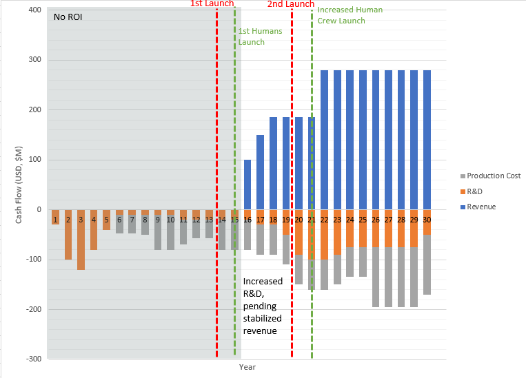
The R&D model for this technology is a long-term investment due to the nature of orbital mechanics, space and safety regulations, and the interplanetary Earth-Mars alignment. Since a ground demonstration will be required and the company will need to be selected as a contractor, we assumed that the first 13 years of the company will not generate revenue and will serve as primarily R&D. During this time, we expect that following a successful ground demonstration in Year 6, production of the first version of autonomous mining drill technology will be initiated with an awarded NASA contract. The initial investment of the technology will launch on year 13 of the program, arriving on Mars during Year 14. The revenue will not begin until Year 16, since it is likely that risk mitigation would call for the successful launch, landing, and execution of in-situ water production on Mars prior to human arrival, when it is assumed revenue will be collected. This model is conservative since all funds are internal; it does not account for government contracts, investors, or grants that could offset the R&D costs. | |||
If the program is successful, a second launch of improved performance technology is expected to occur within the following 6 years, doubling the revenue. This is assumed based on NASA forecasting of humans on Mars and increased demand of water. During this time, there will be a ramp of of R&D since the revenue stream becomes stabilized, allowing the company to maintain current production headcount while increasing R&D resources. | |||
The second wave of R&D will be focused on the next generation of water excavation. By this point, more detailed goals of long-term Martian camps will be determined, allowing for either large stationary reserves, glacier extraction, or advanced hot water water/electrothermal drills. The specific R&D investment portfolio for the 2050+ year forecasting cannot be determined in detail until further missions goals are set by NASA and other potential customers. The research payoff and implementation is not captured beyond 2050 due to uncertainty in the strategic drivers that will be recognized after the deployment and operation of the first launch and updated customer demands. | |||
The R&D | |||
[[File: | [[File:Financialmodelforngtxxerm3.png|6000x6000px|frameless|left]] | ||
| Line 421: | Line 574: | ||
'''Figure 9 ''' - Mars In Situ Mining Extraction Technology | '''Figure 9 ''' - Mars In Situ Mining Extraction Technology | ||
==List of R&D Projects== | |||
The strategy for the R&D projects is unique to this application since this technology and market are in the conceptual phase with limited demonstrated research. The initial strategy will be to focus on reliability and versatility of drilling at various Martian locations and regolith conditions. This will ensure that the technology is competitive enough to be selected as the contractor for in-situ water provider for future human missions to Mars. | |||
This is done by researching and conducting a ground demonstrator of the autonomous mechanical coring drill. The technology shall be demonstrated on Mars analog sites on Earth, such as Icelandic glaciers or Antarctica. The extraction technology is the most efficient approach when optimizing on water extraction, launch mass, and energy consumption. This technology is referred to as the “corer” and takes the form of a dual wall coring auger. | |||
[[File:MarsMiningVehicle.png|500x500px|frameless|left]] | |||
'''Figure 10 ''' - Corer Technology | |||
This is the core technology and crucial to building a reliable reputation, a mandatory requirement in government contract work. This technology is mobile and adaptable to multiple environments, which is necessary since there are multiple location sites of interest for human exploration on the Martian surface. This demonstrator mimics the extraction architecture by Honey Bee Robotics’ most recent experiments on Planetary Volatile Extraction (PVEx). Additional information on this base technology demonstrator can be found in Section: Roadmap Overview. | |||
Once proof of concept and a positive reputation with reliability and geographical versatility is established additional R&D to remain the technology leader will become the focus (pending a successful launch and deployment of the first version of technology). | |||
Electrothermal drills best operate in conditions where the ice is close to the melting temperature. The technology works by melting the ice through an electrothermal process, requiring the liquid water to be pumped out periodically. The technology requires more power than the baseline technology of the mechanical corer. This technology will need to be developed further to reduce power required and understand the ideal atmospheric and geological conditions for performance optimization. However, the technology is scalable up to large diameter holes (not reservoirs), which provides an increase in the performance efficiency FOM, while still maintaining a low launch mass and the ability to remain mobile in water extraction. The figure below depicts the components of the technology, provided by the U.S Ice Drilling Program. | |||
[[File:Electrothermaldrill.png|500x500px|frameless|left]] | |||
'''Figure 11 ''' - Electrothermal Drill Technology | |||
Hot water drills use a drill application to reach the underground glacier ice and deploy a hot water stream into the ice, causing it to melt and forming a natural well. This method requires an initial water supply to heat up and inject into the ice source. Since initial water is required, this new technology would be better suited for a future R&D project where there is already a water supply available. The hot water can reach depths of 30+ meters, where other drill mechanism (mechanical or electrothermal) would not be able to reach while maintaining a low launch mass. The hot water drills are scalable to larger diameter and deeper holes. This technology would increase the performance efficiency FOM for large reservoirs, but would require a set location of long-term Martian camps and thorough understanding of Martian glacier locations. | |||
[[File:HotwaterDrillingPictech.png|500x500px|frameless|left]] | |||
'''Figure 12 ''' - Hot Water Drill Technology | |||
==Technology Strategy Statement== | ==Technology Strategy Statement== | ||
Our technology is contingent on the demand correlated to humans on Mars. The technology would need to arrive on Mars prior to human departure from Earth, which will have about a two year delay due to the Hohmann Transfer launch window. Technology will need to be ground demonstrated prior to launch with capabilities of harvesting and autonomously providing | Our technology is contingent on the demand correlated to humans on Mars. The technology would need to arrive on Mars prior to human departure from Earth, which will have about a two year delay due to the Hohmann Transfer launch window. Technology will need to be ground demonstrated prior to launch with capabilities of harvesting and autonomously providing 24,000 kg of water within a 500-day mission. To be selected as the water supply contractor for the first human missions to Mars, we will need to optimize on launch mass, performance, and reliability. This translates to investments in R&D projects that (1) demonstrates the ability to drill 5 meters or more to ensure a competitive assessment for contract selection, (2) reduces the launch mass, improves reliability, and increases performance of the technology, and (3) forecasts increased water production in stationary locations for long-term Martian camps. Long-term Martian camp water can be conducted by extracting water from glacier reserves or creating "wells" in a station reserve. Hot water drills and electrothermal drills are technologies that may also be researched for improved performance within specific location applications. | ||
==="Swoosh" Chart=== | ==="Swoosh" Chart=== | ||
[[File: | [[File:Swooshchartmarsexc2.png|600x600px|frameless|left]] | ||
'''Figure 11 ''' - Mars In Situ Mining Technology Strategy Arrow | |||
==References== | |||
# Burch, William E., et. al, Pivoting Cutter for Ice Coring Auger. United States Patent US 4,854,396. United States Patent and Trademark Office. 15 Aug. 1989. | |||
# Guy, Dore, et. al, Core Drill and Method of Performing In-Situ Consolidation Testing of Permafrost Soil. Canadian Patent CA 2,875,185. Canadian Patent Office. 15 Dec. 2014. | |||
# Hoffman, S. J., Andrews, A., Joosten, B. K., & Watts, K. (2018). A water rich mars surface mission scenario. 2017 IEEE Aerospace Conference, 1–21. https://doi.org/10.1109/aero.2017.7943911 | |||
# Hughes, O. L., & Terasmae, J. (1963). SIPRE ice-corer for obtaining samples from permanently frozen bogs. Arctic, 16(4), 270-272. | |||
# Koci, B. R., & Kuivinen, K. C. (1984). The PICO lightweight coring auger. Journal of Glaciology, 30(105), 244-245. | |||
#Landworks earth auger specification: https://www.amazon.com/Landworks-Eco-Friendly-Electric-Cordless-Burrowing/dp/B078HB9QR6. [Accessed 10/28/2020] | |||
# Mellor, M. (1975). General considerations for drill system design (No. 264). Corps of Engineers, US Army Cold Regions Research and Engineering Laboratory. | |||
# Sherrit, Stewart, et. al, Single Piezo-Actuator Rotary-Hammering (SPARH) Drill. United States Patent US 8,657,027. United States Patent and Trademark Office. 25 Feb. 2015. | |||
# Sowers, George F., and Christopher B. Dreyer. "Ice mining in lunar permanently shadowed regions." New Space 7.4 (2019): 235-244. | |||
# Ueda, H. T., Sellmann, P. V., & Abele, G. (1975). USA CRREL snow and ice testing equipment (No. 146). Corps of Engineers, US Army Cold Regions Research and Engineering Laboratory. | |||
# Zacny, K., Luczek, K., Paz, A., Hedlund, A. (2016). Planetary Volatiles Extractor (PVEx) for In Situ Resource Utilization (ISRU). Earth and Space 2016 1117. | |||
# Zagorodnov, V., Thompson, L. G., & Mosley-Thompson, E. (2000). Portable system for intermediate-depth ice-core drilling. Journal of Glaciology, 46(152), 167-172. | |||
Latest revision as of 21:02, 7 January 2024
Mars In Situ Mining Technology Roadmap
The technology roadmap identifier:
- 3MIM - Mars In Situ Mining
The number 3 denotes that this is a Level 3 technology roadmap at the subsystem level. A Level 1 would indicate a market level roadmap, Level 2 would be at the product level, and Level 4 at the component level. In reference to our technology, Level 1 would describe the entire system required to mine, filter, and store resources on Mars. Level 2 describes an autonomous mining vehicle, and the sub-system (Level 3) of excavation is defined in this roadmap. A Level 4 technology would consist of a sub-component of the excavation subsystem, such as the drill bit.
Roadmap Overview
Copious resources to construct habitats and sustain life support on Mars are required for long-term manned missions to the "Red Planet". The current state of technology requires that all resources for human survival on Mars must be brought with astronauts or sent from Earth prior to the crew's arrival. However, limitations presented by the cost of sending cargo and mass-launch capabilities of current propulsion would prevent any manned Mars mission to be fully sustained by terrestrial resources. One way to solve this discrepancy is to send technology and machinery to Mars to generate vital resources in situ, or with local materials, prior to human arrival. One vital resource required for human life support will be an ample supply of water. This roadmap focuses on the autonomous mining excavation technology required to accrue water on Mars.
The Mars In Situ Mining extraction technology would fall under the matter transporting category of the functional technology taxonomy. We model our extraction technology on the extraction architecture deemed the most successful by Honey Bee Robotics’ most recent experiments on Planetary Volatile Extraction (PVEx). The extraction technology they deemed the most efficient approach in terms of both water extraction and energy consumption is referred to as the “corer” and takes the form of a dual wall coring auger.
Figure 1 - Mars In Situ Mining Extraction Technology
Figure 1 was created by our team in order to graphically demonstrate the corer technology. The inner wall is composed of heaters, while the outer wall is composed of a composite, insulating material. Once the inner coring drill breaks through the crust and reaches ice, the inner wall begins to heat. Ice sublimation occurs, and the evaporated gas travels between the heated inner wall and insulated outer wall through a surface hood to the cold trap. Deposition occurs in the cold trap, turning the gas back into an ice form.
Technology Hierarchy Tree
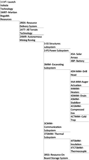
The below technology hierarchy tree shows the break down of technology starting at L1 Technology (Mars Mining) and moving to L2 Technology (Autonomous Mars Mining). Our technology roadmap examines a L3 Technology (Mars In Situ Mining Extraction), which serves as an integral component of Autonomous Mars Mining. Our selected technology can be further broken down into L4 Technologies, such as the coring drill, the inner wall, and the outer wall.
DSM Allocation
Below is the DSM Allocation for the interdependencies of the the systems and subsystems related to the technology roadmap. This diagram corresponds to the hierarchy tree in Figure 2. The extraction technology has numerous co-dependencies of systems, subsystems, and components. This will be further investigated to better understand the performance and timeline tradeoffs for the technology roadmap.
Figure 3 - DSM Martian Mining Technology Roadmap
Key:
Green boxes represent a physical interaction
Blue boxes represent an environmental interaction
Yellow boxes represent a digital interaction
Roadmap Model using Object-Process-Methodology (OPM)
We created an Object-Process-Diagram (OPD) of the Mars In Situ Mining Extraction Technology below in Figure 4. The diagram serves to capture the main object of the roadmap, the corer, its decomposition into sub-components (coring drill, inner wall, outer wall), its characterization by Figures of Merit (FOMs) and the main processes of the system (Drilling, Heating, etc.).
Figure 4 - Mars In Situ Mining Extraction Technology OPD
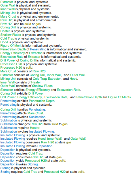
An Object-Process-Language (OPL) description of the above OPD provides a lingual breakdown of the OPD. The OPL is automatically-generated.
Figures of Merit (FOM) Definition
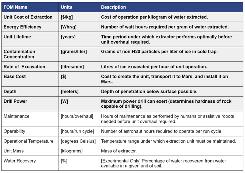
The table below shows a list of figures of merit by which a water extraction technology on Mars could be assessed. As a team we focused heavily on the bolded figures of merit in the table, and included a majority of them in the OPD.
Figure 6 - Mars In Situ Mining Extraction Technology Figures of Merit
Alignment with “Company” Strategic Drivers: FOM targets
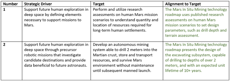
The two strategic drivers represent a breakdown of NASA’s Strategic Objective 2.2, taken from the NASA Strategic Plan 2018. We developed our FOM targets based on NASA's strategic objectives in order to ensure our technology is aligned with our target customer's future mission plans.
Table 1 - Company Strategic Drivers
Positioning of Company vs. Competition: FOM charts
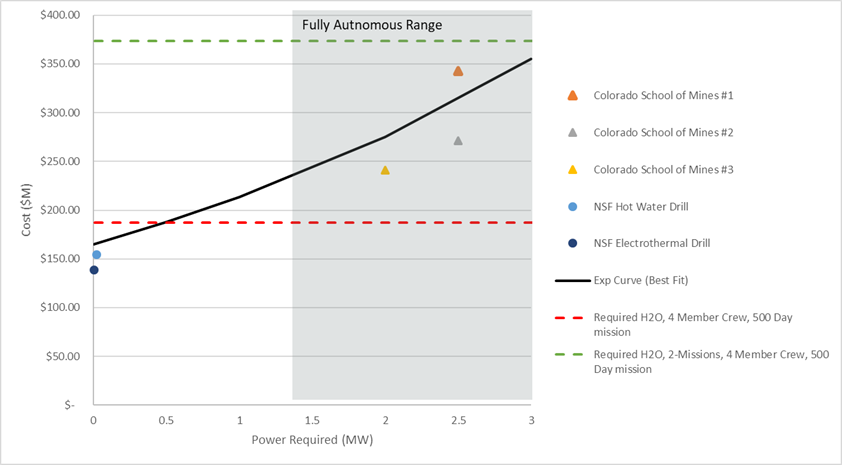
The market for interplanetary mining is still emerging, so to incorporate cost in the trade space of the various versions of celestial drills, a model based equation is used to correlate mass to one-time cost of producing and sending the drill to Mars for operation. The figure demonstrates the power required for operation versus cost as the main trade space of interest. The intent is to eventually normalize the power required by the amount of water extracted to create an efficiency, but that information is not available for the current models and additional analysis is required.
Figure 7 - Market Trade Space for Mars In Situ Mining
The red dotted line represents the threshold for cost to send water to sustain a 4-member Martian crew for 500 days. This is a crucial point since this would determine if the invested cost in a recurring water mining would be worth the investment. The triangles represent a fully autonomous thermal drills. It is noted that the initial cost of the these designs are approximately $150M more expensive, they are more likely to be useful in a long term market since the cost of sending water to Mars one-time is $175M water generation is expected to be a continual requirement with space exploration. Although the initial cost is higher for this method, it creates a continuous operation of water generation.
Technical Model: Morphological Matrix and Tradespace
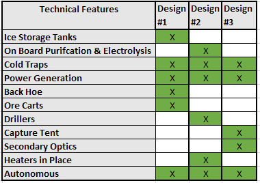
The company decided that having a fully autonomous excavator is important for long-term technology growth and being competitive, the 3 designs from the Colorado School of Mines was selected for further review. Below are the descriptions provided by the Colorado School of Mines shown in the morphological matrix:
Design #1.
Regolith excavated and transported to a central location for heating to sublimate water vapor and collect in a cold trap as ice.
Design #2. Regolith heated in place from heaters within boreholes drilled into the ice field. Ice collected on tarps across surface, tarps reheated at central location to transfer ice to cold traps.
Design #3. Sunlight directed from rim to dome-shaped capture tent for direct heating of the surface. Sublimated water captured in cold traps connected to tent.
The morphological matrix shows the features that each of the designs offer.
Figure 8 - Morphological Matrix
Design #2 was selected as our primary focus because of the autonomous heat trap and includes more technologically advanced processes (ie. electrolysis) for a competitive edge.
An expression for the FOM of drilling rate to power input, or drilling efficiency, was derived. An expression for effective area in which ice is sublimated, or Effective Tent Area was also found.
| Parameter | Symbol | Baseline Value |
|---|---|---|
| Drilling Efficiency | <math>\text{efficiency}</math> | 2.76 e-6 [m^3/s/W] |
| Power Input | <math>\text{Power}_{in}</math> | 99.84 [W] |
| Power Output | <math>\text{Power}_{out}</math> | 83.17 [W] |
| Mechanical Efficiency | <math>\text{n}_{m}</math> | 0.85 |
| Electrical Efficiency | <math>\text{n}_{e}</math> | 0.98 |
| Water Capture Efficiency | <math>\text{n}_{c}</math> | 0.90 |
| Input Voltage | <math>\text{V}</math> | 48 [V] |
| Input Current | <math>\text{I}</math> | 2.08 [A] |
| Water Leak Rate | <math>\text{r}</math> | 10% of Volumetric Drilling Rate |
| Effective Tent Area | <math>\text{A}_{ef}</math> | 633.78 [m^2] |
| Tent Diameter | <math>\text{D}_{tent}</math> | 29 [m] |
| Tent Efficiency | <math>\text{n}_{tent}</math> | 0.96 |
<math> efficiency=(\text{k}\text{n}_{m}\text{n}_{e}\text{I}\text{V} - \text{r})/\text{I}\text{V} </math>
Where, <math> k=\text{R}/\text{Power}_{out} </math>
Now, the physical significance of <math>\text{r}</math> can be re-assigned as an 'efficiency' term; the the water capture efficiency, or<math>\text{n}_{c}</math>. The expression for efficiency now becomes
<math> efficiency=\text{k}\text{n}_{m}\text{n}_{e}\text{n}_{c}</math>
The baseline value of this efficiency, from the table above was found to be 2.76 [cm3/s/W].
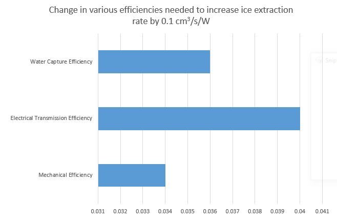
Sensitivity of the drilling efficiency with respect to three system-level efficiencies was carried out. The change in the parameters listed in order to yield a change in drilling efficiency of 0.1 cm3/s/W was calculated from the above equation and the tornado chart is made as shown below.
<math> \text{A}_{ef}=pi*({(\text{D}_{tent}/2)}^2(\text{n}_{tent})) </math>
The baseline value of the Effective Tent Area was found to be 633.78 [m2].
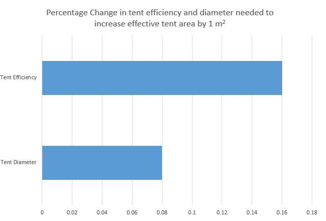
Sensitivity of Effective Tent Area with respect to tent diameter and tent efficiency was carried out. The change in the parameters listed in order to yield a change in Effective Tent Area of 1 m2 was calculated from the above equation and the tornado chart is made as shown below.
Key Publications and Patents
Publications
A Water Rich Mars Surface Mission Scenario
This paper serves as an assessment of how the presence of water on Mars could impact future human Mars mission scenarios. It discusses the location of the most promising water sources, known as feedstock, and analyzes how various rates of water extraction could support different human mission architectures.
The most promising feedstock are massive ice deposits at mid latitudes which bear resemblance to terrestrial glacial features. Various impact craters on these ice deposits expose verified, excavated clean ice under surface regolith. The regolith overburden is estimated to be less than two meters, making drilling to the pure water ice very feasible. Additionally, the location of these ice deposits at mid latitudes make them conducive to a permanent human settlement, unlike feedstock located at the poles.
Planetary Volatiles Extractor for ISRU
This paper describes experiments performed by Honeybee Robotics in which various different mining architectures were tested in their ability to extract ice from rock regolith. The findings and conclusion of this paper inspired our choice in drilling technology for our extracting system.
Three different technologies were tested in an environment simulating Martian temperatures and pressures. These technologies were the sniffer, the mobile in situ water extractor (MISWE), and the corer. The corer was determined to be the most efficient in terms of both power consumption and water extraction, and the least complex of the proposed systems.
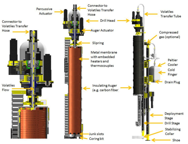
The corer can be described as a dual wall coring auger and is pictured in the figure below. The inner wall is composed of heaters and the outer wall is made of an insulating material. After the drill penetrates the surface and captures a core, the heaters are turned on to sublimate the core. The volatiles will flow between the two walls, staying heated due to the insulated outer wall, into a cold trap on the surface. The insulating outer auger surface results in high power efficiency. The drilling efficiency is also high as opposed to a full face drill because the coring drill only cuts a small annulus. The corer also addresses the predicted problem of losing volatiles that sublime when reached. This is because the sublimed volatiles will flow directly into a capture system, mitigating any loss of resources.
Patents
Pivoting Cutter for Ice Coring Auger
Inventors: William E. Burch, Windsor, Vt.
Assignee: The United States of America as represented by the Secretary of the Army
US Patent 4,854,396
Date: Aug. 8, 1989
This U.S. Army patent describes an apparatus for cutting ice core specimens from a block of ice through the use of swivel cutter elements on the end of an ice coring auger. The swivel cutters swing outwards against the force of the contracting spring when ice is contacted to be cut. Once a core specimen is cut to the desired depth, the coring auger doesn’t continue down, but continues to rotate. Under reactive forces the swivel cutters move inward, resulting in a reduced neckline cut into the ice core specimen, allowing for the specimen to be broken cleanly from the sheet. The reduced in-diameter neck position in the ice core specimen provides a sharp break of the ice core specimen from the ice block.
Single Piezo-Actuator Rotary-Hammering (SPARH) Drill
Inventors: Stewart Sherrit, Xiaoqi Bao, Mircea Badescu, Yoseph Bar-Cohen
Assignee: California Institute of Technology
PCT/US2010/048112
Date: Mar. 17, 2011
This patent describes a low mass, low power, compact coring drill designed to operate under Martian ambient temperatures and pressures. The drill includes a horn actuator having high power piezoelectric materials in order to increase the effectiveness of the actuators. The drill is designed to be optimal for robotic platforms due to its low mass and low power constraints. This patent is important to understand how the materials and dimensions of an extraterrestrial drill increase its competitiveness and ultimately may be the deciding factor on whether it will be a feasible solution.
Core Drill and Method of Performing In-Situ Consolidation Testing of Permafrost Soil
Inventors: Guy Dore, Louis Gosslein, Cedric Flecheux
Assignee: Laval University
Canadian Patent 2,875,185
Date: Dec. 15, 2014
This patent describes an in-situ consolidation testing of permafrost soil, which is ground that is frozen year round. The technology is important to examine as it uses a core drill to apply heat to trapped water resources, similar to the way the dual wall coring auger technology we are examining. The patent’s proposed method applies heat to a sample of permafrost soil to thaw the trapped ice, and then extracts the thawed ice using downward longitudinal pressure to drain water from the sample. The objective of this method is to remove the water from the core sample, whereas the objective of our dual wall coring auger is to remove water from the regolith. While these two objectives remain different, studying the heating mechanisms and power supply of a similar technology is beneficial to compare to our dual wall coring auger.
Financial Model
The R&D model for this technology is a long-term investment due to the nature of orbital mechanics, space and safety regulations, and the interplanetary Earth-Mars alignment. Since a ground demonstration will be required and the company will need to be selected as a contractor, we assumed that the first 13 years of the company will not generate revenue and will serve as primarily R&D. During this time, we expect that following a successful ground demonstration in Year 6, production of the first version of autonomous mining drill technology will be initiated with an awarded NASA contract. The initial investment of the technology will launch on year 13 of the program, arriving on Mars during Year 14. The revenue will not begin until Year 16, since it is likely that risk mitigation would call for the successful launch, landing, and execution of in-situ water production on Mars prior to human arrival, when it is assumed revenue will be collected. This model is conservative since all funds are internal; it does not account for government contracts, investors, or grants that could offset the R&D costs.
If the program is successful, a second launch of improved performance technology is expected to occur within the following 6 years, doubling the revenue. This is assumed based on NASA forecasting of humans on Mars and increased demand of water. During this time, there will be a ramp of of R&D since the revenue stream becomes stabilized, allowing the company to maintain current production headcount while increasing R&D resources.
The second wave of R&D will be focused on the next generation of water excavation. By this point, more detailed goals of long-term Martian camps will be determined, allowing for either large stationary reserves, glacier extraction, or advanced hot water water/electrothermal drills. The specific R&D investment portfolio for the 2050+ year forecasting cannot be determined in detail until further missions goals are set by NASA and other potential customers. The research payoff and implementation is not captured beyond 2050 due to uncertainty in the strategic drivers that will be recognized after the deployment and operation of the first launch and updated customer demands.
Figure 9 - Mars In Situ Mining Extraction Technology
List of R&D Projects
The strategy for the R&D projects is unique to this application since this technology and market are in the conceptual phase with limited demonstrated research. The initial strategy will be to focus on reliability and versatility of drilling at various Martian locations and regolith conditions. This will ensure that the technology is competitive enough to be selected as the contractor for in-situ water provider for future human missions to Mars.
This is done by researching and conducting a ground demonstrator of the autonomous mechanical coring drill. The technology shall be demonstrated on Mars analog sites on Earth, such as Icelandic glaciers or Antarctica. The extraction technology is the most efficient approach when optimizing on water extraction, launch mass, and energy consumption. This technology is referred to as the “corer” and takes the form of a dual wall coring auger.
Figure 10 - Corer Technology
This is the core technology and crucial to building a reliable reputation, a mandatory requirement in government contract work. This technology is mobile and adaptable to multiple environments, which is necessary since there are multiple location sites of interest for human exploration on the Martian surface. This demonstrator mimics the extraction architecture by Honey Bee Robotics’ most recent experiments on Planetary Volatile Extraction (PVEx). Additional information on this base technology demonstrator can be found in Section: Roadmap Overview.
Once proof of concept and a positive reputation with reliability and geographical versatility is established additional R&D to remain the technology leader will become the focus (pending a successful launch and deployment of the first version of technology).
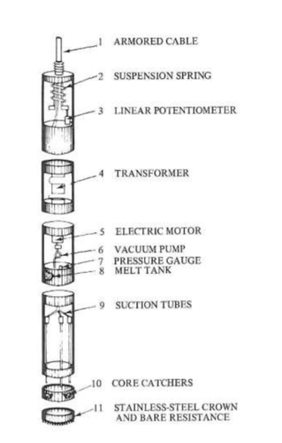
Electrothermal drills best operate in conditions where the ice is close to the melting temperature. The technology works by melting the ice through an electrothermal process, requiring the liquid water to be pumped out periodically. The technology requires more power than the baseline technology of the mechanical corer. This technology will need to be developed further to reduce power required and understand the ideal atmospheric and geological conditions for performance optimization. However, the technology is scalable up to large diameter holes (not reservoirs), which provides an increase in the performance efficiency FOM, while still maintaining a low launch mass and the ability to remain mobile in water extraction. The figure below depicts the components of the technology, provided by the U.S Ice Drilling Program.
Figure 11 - Electrothermal Drill Technology
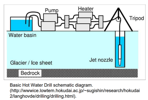
Hot water drills use a drill application to reach the underground glacier ice and deploy a hot water stream into the ice, causing it to melt and forming a natural well. This method requires an initial water supply to heat up and inject into the ice source. Since initial water is required, this new technology would be better suited for a future R&D project where there is already a water supply available. The hot water can reach depths of 30+ meters, where other drill mechanism (mechanical or electrothermal) would not be able to reach while maintaining a low launch mass. The hot water drills are scalable to larger diameter and deeper holes. This technology would increase the performance efficiency FOM for large reservoirs, but would require a set location of long-term Martian camps and thorough understanding of Martian glacier locations.
Figure 12 - Hot Water Drill Technology
Technology Strategy Statement
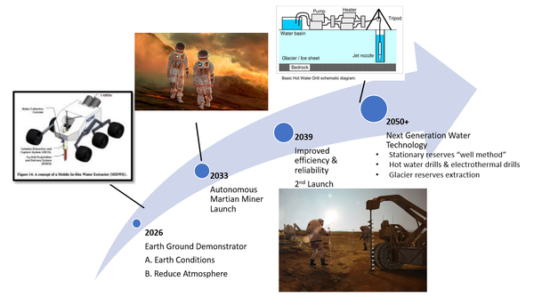
Our technology is contingent on the demand correlated to humans on Mars. The technology would need to arrive on Mars prior to human departure from Earth, which will have about a two year delay due to the Hohmann Transfer launch window. Technology will need to be ground demonstrated prior to launch with capabilities of harvesting and autonomously providing 24,000 kg of water within a 500-day mission. To be selected as the water supply contractor for the first human missions to Mars, we will need to optimize on launch mass, performance, and reliability. This translates to investments in R&D projects that (1) demonstrates the ability to drill 5 meters or more to ensure a competitive assessment for contract selection, (2) reduces the launch mass, improves reliability, and increases performance of the technology, and (3) forecasts increased water production in stationary locations for long-term Martian camps. Long-term Martian camp water can be conducted by extracting water from glacier reserves or creating "wells" in a station reserve. Hot water drills and electrothermal drills are technologies that may also be researched for improved performance within specific location applications.
"Swoosh" Chart
Figure 11 - Mars In Situ Mining Technology Strategy Arrow
References
- Burch, William E., et. al, Pivoting Cutter for Ice Coring Auger. United States Patent US 4,854,396. United States Patent and Trademark Office. 15 Aug. 1989.
- Guy, Dore, et. al, Core Drill and Method of Performing In-Situ Consolidation Testing of Permafrost Soil. Canadian Patent CA 2,875,185. Canadian Patent Office. 15 Dec. 2014.
- Hoffman, S. J., Andrews, A., Joosten, B. K., & Watts, K. (2018). A water rich mars surface mission scenario. 2017 IEEE Aerospace Conference, 1–21. https://doi.org/10.1109/aero.2017.7943911
- Hughes, O. L., & Terasmae, J. (1963). SIPRE ice-corer for obtaining samples from permanently frozen bogs. Arctic, 16(4), 270-272.
- Koci, B. R., & Kuivinen, K. C. (1984). The PICO lightweight coring auger. Journal of Glaciology, 30(105), 244-245.
- Landworks earth auger specification: https://www.amazon.com/Landworks-Eco-Friendly-Electric-Cordless-Burrowing/dp/B078HB9QR6. [Accessed 10/28/2020]
- Mellor, M. (1975). General considerations for drill system design (No. 264). Corps of Engineers, US Army Cold Regions Research and Engineering Laboratory.
- Sherrit, Stewart, et. al, Single Piezo-Actuator Rotary-Hammering (SPARH) Drill. United States Patent US 8,657,027. United States Patent and Trademark Office. 25 Feb. 2015.
- Sowers, George F., and Christopher B. Dreyer. "Ice mining in lunar permanently shadowed regions." New Space 7.4 (2019): 235-244.
- Ueda, H. T., Sellmann, P. V., & Abele, G. (1975). USA CRREL snow and ice testing equipment (No. 146). Corps of Engineers, US Army Cold Regions Research and Engineering Laboratory.
- Zacny, K., Luczek, K., Paz, A., Hedlund, A. (2016). Planetary Volatiles Extractor (PVEx) for In Situ Resource Utilization (ISRU). Earth and Space 2016 1117.
- Zagorodnov, V., Thompson, L. G., & Mosley-Thompson, E. (2000). Portable system for intermediate-depth ice-core drilling. Journal of Glaciology, 46(152), 167-172.
