Difference between revisions of "Hypersonic Transport Vehicles"
| Line 16: | Line 16: | ||
An OPM diagram showing a sample of the processes required for the creation and operation of commercial hypersonic transport vehicles is shown below. Note that the technology of interest (hypersonic transport vehicle) is shown near the center of the figures. The hypersonic transport vehicle serves to transport passengers from one location to another (also indicated near the center of the diagram). FOMs are shown towards the bottom right, with connections to relevant processes. It is noted that the sub-technologies shown in the diagram (high-temperature materials and structures, variable fidelity modeling, and combined-cycle engines) are discussed in detail by Bowcutt in [5]. | An OPM diagram showing a sample of the processes required for the creation and operation of commercial hypersonic transport vehicles is shown below. Note that the technology of interest (hypersonic transport vehicle) is shown near the center of the figures. The hypersonic transport vehicle serves to transport passengers from one location to another (also indicated near the center of the diagram). FOMs are shown towards the bottom right, with connections to relevant processes. It is noted that the sub-technologies shown in the diagram (high-temperature materials and structures, variable fidelity modeling, and combined-cycle engines) are discussed in detail by Bowcutt in [5]. | ||
[[File: | [[File:Hypersonic_OPM.jpg|800px|center]] | ||
==Figures of Merit== | ==Figures of Merit== | ||
Revision as of 13:53, 8 October 2023
System Overview
Hypersonic transport vehicles are a type of aircraft from the wider group of hypersonic systems. Hypersonic systems are all vehicles that operate in the flight regime where aerodynamic heating becomes significant, typically thought of as flight faster than Mach 5. Such systems include most atmospheric entry vehicles, some orbital launch vehicles, and several types of ballistic or maneuvering missiles. Hypersonic transport vehicles aim to move personnel and cargo from place to place much faster than traditional transonic or even supersonic aircraft. With a commercial application, this would be accomplished with the aim of generating profit for the company providing the transport service.
Roadmap Hierarchy
In Progress
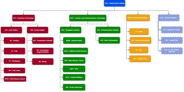
The technology hierarchy demonstrates that such technologies as metal 3-D printing and modulable launchpads are supporting the development of small launchers. Initiatives and development plans for these technologies enhance small launchers by increasing their reusability, launch rate, scheduling flexibility, and reducing their cost per kilogram to launch payloads into orbit.
Design Structure Matrix (DSM) Allocation
Roadmap Model Using Object-Process Methodology (OPM)
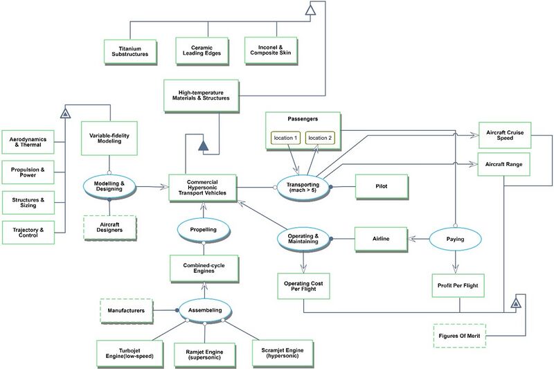
An OPM diagram showing a sample of the processes required for the creation and operation of commercial hypersonic transport vehicles is shown below. Note that the technology of interest (hypersonic transport vehicle) is shown near the center of the figures. The hypersonic transport vehicle serves to transport passengers from one location to another (also indicated near the center of the diagram). FOMs are shown towards the bottom right, with connections to relevant processes. It is noted that the sub-technologies shown in the diagram (high-temperature materials and structures, variable fidelity modeling, and combined-cycle engines) are discussed in detail by Bowcutt in [5].
Figures of Merit
The figures of merit (FOMs) relevant to commercial hypersonic transports include the distance covered per time (speed, v), aircraft range R, operating cost per flight C_O, and the aircraft profit per flight p. The profit p generated by the airline may be the single most important figure of merit, as it is the ultimate driver for the existence of commercial hypersonic vehicles (without profit, airlines will not offer such a service). These FOMs are described mathematically with nominal values in the table below.
| Figure of Merit (FOM) | Unit | Description |
|---|---|---|
| Scheduling flexibility | [weeks or months or years] | How quickly the launch vehicle can go from initial talks with customer to launch to LEO. (Sometimes called Responsiveness, it is the duration between the launch window and the notification of its flight parameters - orbit, latitude, date, etc.) |
| Launch Frequency | [launches/month] | The number of launches a launch vehicle can perform in a month |
| Cost per kg | [$/kg of payload to LEO] | The total cost of the launch divided by the amount of payload to 500km LEO |
| Reliability | [% of successful launches] | The percentage of launches out of total launches that are successful as determined by ability to meet end requirements of customers |
| Payload mass capacity | [kg of payload to 500km LEO] | The amount of payload in kilograms that can be launched to 500km Low Earth Orbit (LEO) with the launch vehicle. LEO is a large range and so this FOM standardizes the various launch vehicles by specifying 500km LEO |
| Total cost | [$] | The total cost of the launch, which is complementary to the cost per kg as it indicates the price of a ticket for a customer to get a dedicated launch (with dedicated orbit parameters, etc.). |
| Reusability | [Number of reuse cycles] | The number of times a launch vehicle can be reused before a new one must be built |

