Difference between revisions of "Nuclear Fusion"
| Line 68: | Line 68: | ||
'''Gain factor (Q-Value) = (Energy produced by fusion reactions) / (External energy input to the plasma)''' | '''Gain factor (Q-Value) = (Energy produced by fusion reactions) / (External energy input to the plasma)''' | ||
===Triple product=== | ===Triple product=== | ||
Revision as of 18:31, 5 December 2023
Technology Roadmap Sections and Deliverables
- 1NCF - Nuclear Fusion
Roadmap Overview
Fusion power refers to the generation from the energy released by merging, or fusing, two atomic nuclei to generate energy. The energy generated from this reaction comes from the difference in mass between the two individual nuclei and the resulting lighter nucleus; this difference in mass is converted to energy according to Einstein’s famous equation, E=mc^2. There are different atoms that can be combined to generate fusion energy, but the most common reaction explored for commercial purposes involves two isotopes of hydrogen, deuterium, and tritium, in a reaction referred to as DT fusion. These two isotopes are brought in close proximity in a fusion reactor at over 100 million Celsius and combine to produce helium, releasing high-energy neutrons that can be captured to generate heat and run a conventional turbine to generate electricity.
D+T -> He+n
where
- D: Deuterium
- T: Tritium
- He: Helium
- n: neutron
Fusion reactions occur when two or more nuclei come close enough to each other for a long enough time that the nuclear forces attracting the nuclei exceed the electrostatic forces pulling them apart, fusing them into a heavier nucleus. To realize nuclear fusion for energy generation, there are technical challenges, such as plasma control and energy supply, to create and maintain high temperatures and high pressure.
There are multiple reactor concepts being explored to enable a fusion reaction, which involve the use of a strong magnetic field (magnetic confinement), powerful lasers (inertial confinement), or a hybrid of inertial and magnetic confinement methods (e.g., magneto-inertial confinement). The main applicable markets for fusion power are the electricity market, industrial heat, and space propulsion.
Design Structure Matrix (DSM) Allocation
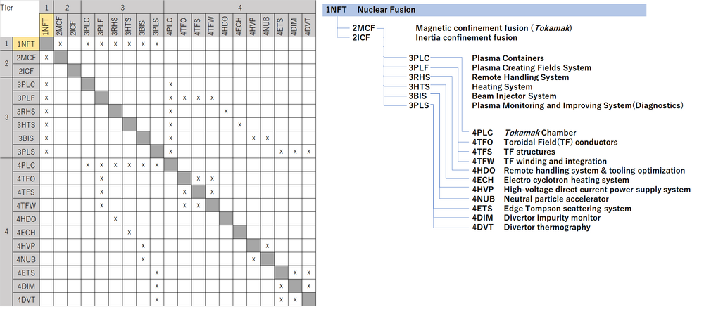
The picture above is 1NCF nuclear fusion tree. The 'Tokamak' represents one of the approaches within Magnetic Confinement Fusion. It is a device specifically designed for nuclear fusion that confines high-temperature plasma using an axisymmetric toroidal (doughnut-shaped) magnetic field. As a container for plasma, it is associated with the level 3 subsystems, as depicted in the DSM.
The DSM and tree both show that 1NCF(2MCF) requires the following technologies at the subsystem level 3:
- 3PLC Plasma Containers
- 3PLF Plasma Creating Fields System
- 3RHS Remote Handling System
- 3HTS Heating System
- 3BIS Beam Injector System
- 3PLS Plasma Monitoring and Improving System(Diagnostics)
Each level 3 subsystem also require enabling technologies shown as level 4 systems:
- 4PLC Tokamak Chamber
- 4TFO Toroidal Field(TF) conductors
- 4TFS TF structures
- 4TFW TF winding and integration
- 4HDO Remote handling system & tooling optimization
- 4ECH Electro cyclotron heating system
- 4HVP High-voltage direct current power supply system
- 4NUB Neutral particle accelerator
- 4ETS Edge Tompson scattering system
- 4DIM Divertor impurity monitor
- 4DVT Divertor thermography
Roadmap Model using OPM
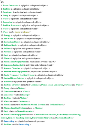
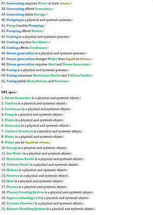
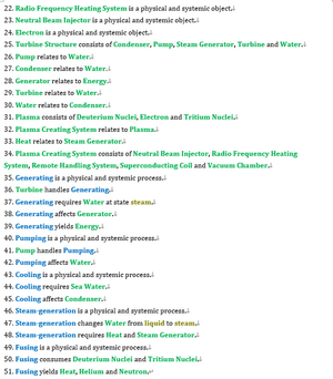
The OPM and OPL of one possible fusion technology system are depicted below. This technology assists in harnessing nuclear energy to generate power with lower risk than nuclear generation in a controlled environment and produces less radioactive waste.
Figures of Merit
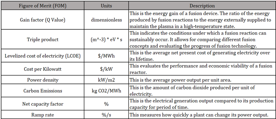
The table below shows a list of FOMs of nuclear fusion.
Cost per Kilowatt, Power density, Carbon Emissions, Net capacity factor, Ramp rate are figures of merit relevant to the electricity market. These metrics of fusion energy are vital indicators of its competitiveness compared to other energy sources such as solar, wind, and fossil fuels.
Gain factor(Q-Value)
The Q-value is a crucial metric for evaluating the performance and viability of a fusion device. A device with a high Q-value suggests a significant net energy gain, increasing its potential as a practical energy source.
Gain factor (Q-Value) = (Energy produced by fusion reactions) / (External energy input to the plasma)
Triple product
Triple product can be used to compare performance across various approaches to fusion, such as magnetic confinement schemes, inertial confinement schemes, and magneto-inertial schemes, being independent of the scheme used to create the fusion plasma. It is defined as the product of three factors: plasma density, temperature, and confinement time. Triple produc is expressed as:
Triple product ((m^-3) * eV * s) =density(1/m^3) × temperature(eV) × confinement time (s)
Where
- Density is the number of nuclei per unit volume
- Temperature is the kinetic energy of the particles in the plasma (the unit for temperature in fusion contexts is usually expressed in electron volts (eV))
- Confinement Time is the average time that a particle remains in the plasma before escaping.
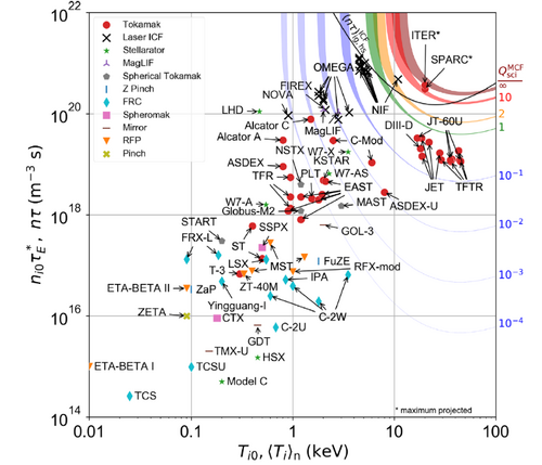
The triple product is the main figure of merit used to measure progress in fusion energy research. Even though cost-per-KW is more appropriate when comparing power generation technologies, fusion technology is at too early stages to come up with reliable estimates of cost and progress over time. Figure 1 below shows the record values for a given fusion confinement concept along with the theoretical limit [1]. This theoretical limit occurs due to operational limits in plasma density, and a parameter called beta, β, the ratio of plasma pressure to magnetic pressure [2].
Figure 1. Triple product achieved for various fusion confinement concepts [1]
The rate of improvement was estimated for Magnetic Confinement fusion (red line in Figure 1); this is shown in Figure 2. The rate of improvement was found to be uneven, with large values at the beginning ~200% and then slowing down to about 35%. This decreased rate of improvement is well documented in the literature and is attributed to the international research community focusing on the International Thermonuclear Experimental Reactor (ITER). This particular confinement method appears to be in the portion of the S curve with slower progress. In contrast, the Inertial confinement fusion (black line in Figure 2) appears to be in the rapid progress phase (the rate of improvement was not calculated)
Figure 2. Rate of improvement for the triple product of magnetic confinement fusion. Raw data obtained from ref. [1].
Levelized cost of electricity (LCOE)
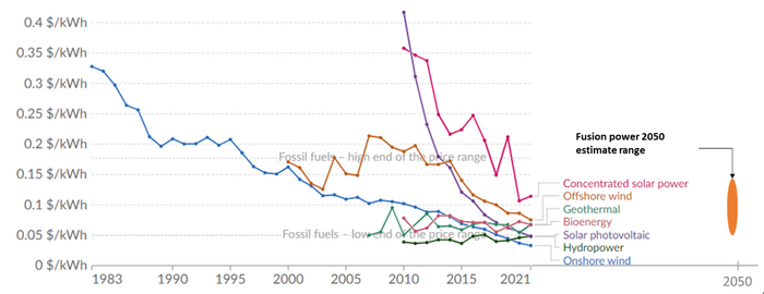
The most important FOM for power generation is the levelized cost of energy (LCOE). However, with the increased awareness of the negative impacts of carbon emissions and the policy trends on carbon caps and taxes, a FOM that is increasing in importance is the amount of emissions (particularly carbon dioxide) generated per unit of power. This is evident from the increased adoption of renewable energy sources. However, renewables fall short on at least two FOMs: power density (power per unit of area) and capacity factor (due to their intermittent nature). This represents an opportunity for fusion technologies to disrupt the electricity market, as it not only produces zero carbon emissions, but is also dispatchable (not intermittent in nature), and has significantly high energy density compared to other renewable sources. Even though the current projections for the LCOE of fusion power are highly uncertain and the conservative cost projections are not necessarily competitive with other power generation sources [3], they bring a unique combination of superior performance in other increasingly important FOMs such that when the LCOE projections become sufficiently low (assuming some of the technical challenges affecting economic viability are resoled), there will be a high likelihood of becoming a disruptive technology. Given the low maturity of the technology, it is not possible to plot FOM improvement over time for fusion in terms of FOMs that are relevant in electricity markets. Nevertheless, current projections for the main FOM (LCOE) compared to other technologies is shown in Figure 3.
Figure 3 Levelized cost of energy by technology [4]. LCOE projections for fusion power were taken from two recent estimates [3] [5]
Alignment with Company Strategic Drivers
This roadmap is for a hypothetical fusion startup aiming to develop a competitive magnetically confined fusion reactor concept. The key strategic FOM targets for the first experimental reactor for this company are the following:
| FOM | Target |
|---|---|
| Gain (Q) | 10 |
| Fusion Power | 100MW |
Positioning of Company vs. Competition
The positioning of the company with respect to the gain factor (Q) and triple product are shown below (purple star) (Taken from [6])
Technical Model
The two figures of merit (FOM) explored for sensitivity analysis of magnetic confinement fusion are
1) fusion power 〖(P〗_fus) and 2) scientific gain factor 〖(Q〗_sci). A description of these two FOMs, along with the key design parameters is provided below: Fusion power P_fus: refers to the magnitude of thermal power generated within a fusion reactor (MW). The power released from a deuterium-tritium DT fusion reaction can be described by the following equation [6]:
Where n is the number density of the reactants, 〈σv〉_DT is the reactivity of the DT fuel, E_DT is the total energy released per fusion reaction, and V_P is the volume of the plasma. As shown in various sources, this equation can be modified to reflect an expression of key reactor design parameters: magnetic field strength (B), toroidal radius (R) and normalized pressure 〖(β〗_N):
2) Scientific gain Q_sci: The ration of the power generated in the fusion reaction to the externally provided heating power (unitless). The derivation of the equation in terms of useful parameters is not straightforward and beyond the scope of this class, only its relationship to useful design parameters is shown below for a tokamak [7]:
The sensitivity for these two FOMs was evaluated for magnetic field strength (B), toroidal radius (R) and normalized pressure 〖(β〗_N). The reactor being built at the International Thermonuclear Experimental Reactor (ITER) was used as reference reactor, with a P_fus of 500MW and Q_sci of 10 for simplicity. To study the sensitivity of the two FOMs to these design parameters, the three design parameters (B, R, BN) were varied from low values (75% the reference value, or a factor of 0.75) to high values (125% the reference value). The results from the sensitivity analysis are shown in the figures below.
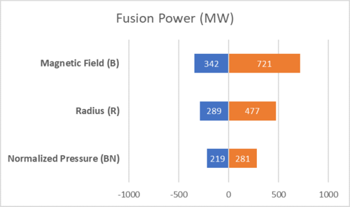
Figure 4. Sensitivity analysis of fusion power to key design parameters. The “0” value represents a reference value of 500MW.
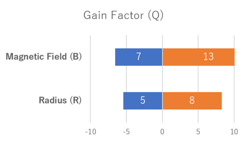
Figure 5. Sensitivity analysis of the gain factor to key design parameters. The “0” value represents a gain of 10.
As can be seen in the figures above, a strong dependence can be seen on the magnetic field strength (B). This explains the relatively recent push in the private fusion sector to implement high-temperature super conductive magnets that can result in higher reactor performance with high power densities, such as Commonwealth Fusion Systems in the US and Tokamak Energy in the UK. The effect of larger radius explains the push to larger reactor designs in the evolution of fusion research (before breakthroughs in higher magnetic field HTS magnets). Finally, the effect of beta pressure is reflected in the pursuit of various magnetic confinement reactor geometries and configurations such as Tokamak, spherical tokamaks, stellarators, spheromak, etc., all of which implement magnetic confinement but can achieve different normalized pressure (BN).
Morphological Matrix
Below is a morphological matrix showing the main design options for a magnetically confined fusion reactor.
| Option #1 | Option #2 | Option #3 | |
|---|---|---|---|
| Confinement duration | continuous | long pulse | N/A |
| Magnetic field topology | Open | Closed | N/A |
| Aspect ratio (major/minor radius) | High | Medium | Low |
| Poloidal field source | Electric current | Magnetic field | N/A |
| Toroidal field strength | None | Moderate | High |
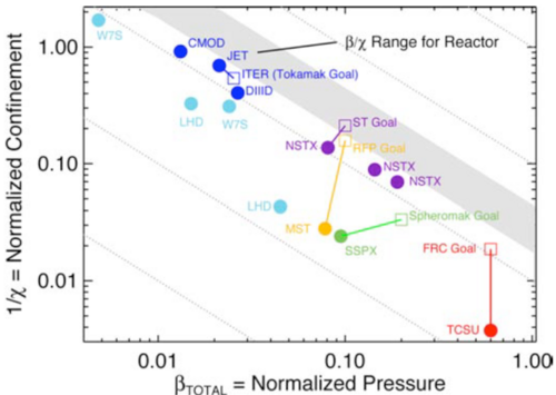
The various reactor concepts being explored both by research organizations and the private sector represent a combination of these options (tokamak, stellarator, spheromak, field-reversed configuration). These different options represent trade-offs in terms of plasma performance and design complexity (which relates to cost). Since a direct performance vs cost comparison is not possible given the early stages of reactor development and cost uncertainties, the approach taken by Shefield’s analysis [8] is used to form the basis of an initial trade space. In this approach, the ratio of normalized pressure〖 (β〗_N) to thermal diffusivity (χ) is calculated〖 (β〗_N/χ).
As shown above,〖 β〗_N is related to power density (quadratic relationship). Higher values of 〖 β〗_N are desired and can be achieved with increased magnetohydrodynamic stability inherent to the reactor design choices above [9].
Thermal diffusivity (χ) measures plasma energy transport and is inversely proportional to energy confinement time; confinement time is the time it takes for the plasma to lose its energy due to losses. Therefore, low values of thermal diffusivity are desired [9].
The figure below shows the normalized pressure versus thermal diffusivity for various magnetic confinement experimental reactor concepts and design goals. This figure was taken from [9] and and will be used as a starting point for a tradespace comparing alternate reactor concepts.
Blue: tokamak, Light blue: Stellarator, purple: spherical tokamak, yellow: reversed-field pinch, green: spheromak, red: field-reversed configuration [9]
Keys Publications and Patents
- Publication
These are two articles related to the development of Magnetic Confinement Fusion (MCF).
The first article provides a comprehensive overview of MCF development, including major projects like ITER and DEMO, as well as a wide range of issues such as safety, management, and decommissioning towards the realization of fusion energy. The second article describes a new architecture to the design of the tokamak magnetic control device, highlighting significant recent advancements in tokamak feedback control.
“Magnetic-confinement fusion”
J. Ongena, R. Koch, R. Wolf & H. Zohm
Nature Physics volume 12, pages398–410 (2016)
The article discusses the potential of Magnetic-confinement nuclear fusion as an environmentally friendly energy solution, mentioning significant advancements in magnetic fusion technology. It highlights the construction of ITER, a fusion device aimed at demonstrating a tenfold power multiplication, and discusses the basic physics of magnetic fusion, safety, waste management, and decommissioning of future fusion power plants.
“Magnetic control of tokamak plasmas through deep reinforcement learning”
Jonas Degrave, Federico Felici, Jonas Buchli, Michael Neunert, Brendan Tracey, Francesco Carpanese, Timo Ewalds, Roland Hafner, Abbas Abdolmaleki, Diego de las Casas, Craig Donner, Leslie Fritz, Cristian Galperti, Andrea Huber, James Keeling, Maria Tsimpoukelli, Jackie Kay, Antoine Merle, Jean-Marc Moret, Seb Noury, Federico Pesamosca, David Pfau, Olivier Sauter, Cristian Sommariva
Nature volume 602, pages414–419 (2022)
In this article, the authors propose a promising path toward sustainable energy using magnetic confinement for nuclear fusion, particularly in the tokamak configuration. The primary challenge is to form and maintain a high-temperature plasma within the tokamak vessel. This necessitates high-dimensional, high-frequency closed-loop control using magnetic actuator coils, further complicated by the diverse requirements spanning a wide range of plasma configurations. We have introduced a novel architecture for the tokamak magnetic controller design in this research, autonomously commanding the full set of control coils. This demonstrates a significant advance in tokamak feedback control, showcasing the potential of reinforcement learning to accelerate research in the fusion domain.
- Patents
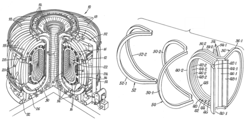
These are two patents for designing plasma confinement mechanisms in the early stages of Magnetic Confinement Fusion (MCF) development. Initially filed in 1969 and 1977, the patents have expired.
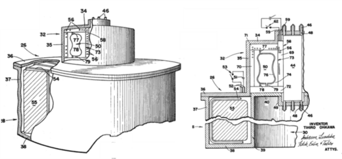
“APPARATUS FOR FORMING AND CONTAINING PLASMA” (1969)
Tihiro Ohkawa, La Jolla, Calif., assignor to the United States of America as represented by the Atomic Energy Commission
Filed Mar. 21, 1969, Ser. No. 809,280
Int. Cl. G21b 1/00
This patent covers the design of an apparatus engineered to create and contain plasma. This is an essential part of Magnetic Confined Fusion. Initially filed in 1969, the patent has since expired.
A plasma method and apparatus are provided with a toroidal plasma confinement region in which a toroidal magnetic field is produced by external magnetic field-producing means. A toroidal electric field is induced within the region by conductors disposed of outside of the plasma region so as to produce and maintain a plasma current. The electric field is produced without producing any substantial additional magnetic field in the region. A second magnetic field in the region is produced by means disposed outside the region so as to provide a plurality of nests of closed toroidal flux surfaces in the toroidal plasma region, thus approximating a field produced by conductors within the region without the losses associated therewith.
Figure 6. A perspective view of a plasma apparatus (portions being broken
away to show certain features)
“Toroidal Magnet System” (1977) Tihiro Ohkawa, La Jolla, Calif.; Charles C. Baker, Naperville, Il. Assignee: The United States of America as represented by the United States Department of Energy, Washington, D.C. Appl. No.: 864,696 Filed: Dec. 27, 1977 Int. Cl.: G21b 1/00
This invention relates generally to devices that utilize a toroidal magnetic field and more particularly to toroidal coil systems with demountable toroidal coil elements disposed about a toroidal containment vessel.
One of the more challenging problems in designing toroidal plasma devices is the development of suitable assembly/disassembly and maintenance methods. The fact that the toroidal field coils of such a device link to a toroidal plasma containment vessel makes access to the device's interior very difficult. In this invention, a toroidal coil system is provided which utilizes two different types of coils: one in which field-generating coils link | the toroidal containment vessel and one in which field-correcting coils do not link any component of the device. The unlinked coils can be easily pulled back from the device, providing much-improved access. This invention finds particular utility in experimental devices and the use thereof in experimentation and investigation with respect to toroidal plasma devices like those of the tokamak type.
Figure 7. An isometric view of a plasma device and an isometric view of a preferred toroidal coil in a partly disassembled condition
Financial Model
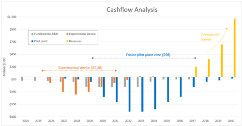
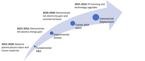
The Company aims to demonstrate its technology within the next 10 years through a combination of R&D projects, a small-scale experimental device to demonstrate plasma physics, and a larger-scale pilot plant to demonstrate electricity generation (more details below). After the technology has been demonstrated, the Company plans to generate revenue from its intellectual property through licensing to power generation project developers. Taking this strategy into account, a financial model was prepared using the assumptions below:
Assumptions:
1. Experimental device detailed design & and construction in the 2025-2030 timeframe
2. Pilot plant detailed design & and construction in the 2027-2035 timeframe
3. Pilot plant will operate during the 2035-2045 timeframe
4. Owners or operators carry the cost of building commercial power plants, the Company issues a license
5. The license costs $200M upfront for a 1GW power plant
6. Commercial power plants begin construction in the early 2040s, but licenses are issued as early as 2037
7. Sales grow at a 60% YoY in the first 5 years
8. Revenues come from licensing the technology; no costs associated with building commercial plants
9. Total installed capacity reaches approximately $1TW by 2050
10. Discount rate = 10%
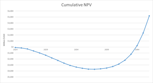
With these assumptions, financial projections show that financial breakeven occurs at around 2045 and revenues increase exponentially from that point, with relatively low costs afterward to upgrade and improve the technology.
List of R&D Projects
The following list shows a highly summarized list of R&D activities and demonstration projects:
1. Technology development:
- Materials: develop plasma-facing and first-wall components that can withstand the extreme heat loads, temperatures and neutron irradiation inside the reactor
- High-temperature superconducting magnets (HTS): demonstrate performance at high field strength for plasma confinement and high power density
- Modeling and simulation of plasma and device performance to optimize reactor design.
2. Experimental reactor device: This effort consists of building a small scale reactor capable of producing 100MW of fusion power and demonstrate scientific gain (Qsci) higher than 1, at least 100 million degrees Celsisus and a triple product greater than 2 x 10²¹ keV s m-3. The experimental plant is expected to begin commissioning in 2030.
3. Fusion pilot plant: larger scale (~500MW fusion power and at least 50MWe) plant built to demonstrate that the technology is mature enough to begin commercial deployment. Among other things, the pilot plant will demonstrate net electricity gain (Qp much higher than 1), sufficient confinement time, safe operation, durability, reliability, availability, and economic feasibility. The fusion power plant will begin operation in the mid-late 2030s; the Company will purely focus on the fusion reactor (it will partner with other companies for other required power plant components).
Technology Strategy Statement
Our target is to develop the intellectual property required to build the fusion reactor core of future commercial power plants to be able to license our IP to utility-scale projects in the late 2040s. To achieve our targets, we will progressively mature our technology through a series of R&D projects related to fusion materials, high-temperature superconducting magnets, and simulation and modeling of the plasma. We will proceed with demonstrating net fusion plasma energy gain through an experimental device producing 100MW of fusion power that will begin operating in 2030. This experimental device will be followed by a fusion pilot plant capable of producing 50MW of electricity and proving that the technology is economically viable and fit for commercial deployment. These targets will enable revenue in the late 2040s through licensing the IP to public and private plant developers.
Bibliography
[1] S. E. Wurzel, "Progress toward fusion energy breakeven and gain as measured against the Lawson criterion," Physics of Plasmas, 2022
[2] A. Costley, "On the fusion triple product and fusion power gain," Nuclear Fusion, Volume 56, Number 6
[3] L. e. al., "Can fusion energy be cost-competitive and commercially viable? An analysis of magnetically confined reactors," Energy Policy, vol. 177, 2023.
[4] "Levelized cost of energy by technoloty, World," Our World in Data, [Online]. Available: https://ourworldindata.org/grapher/levelized-cost-of-energy.
[5] E. e. al., "Approximation of the economy of fusion energy," Energy, vol. 152, 2018.
[6] S. E. Wurzel, "Progress toward fusion energy breakeven and gain as measured against the Lawson criterion," Physics of Plasmas, 2022.
[7] D. Whyte, "Small, modular and economically attractive dusion enabled by high temperature superconductors," Phil. Trans. R. Soc. A 377, no. http://dx.doi.org/10.1098/rsta.2018.0354, 2019.
[8] J. Sheffield, "Physics requirements for an attractive magnetic fusion reactor," Nuclear Fusion, vol. 25, no. 12, p. 1733, 1985.
[9] "Report of the FESAC Toroidal Alternates Panel," 2008.
The information in the Financial Model, List of R&D Projects, and Technology Strategy Statement sections was inspired by the following documents:
- National Academies of Sciences, Engineering, and Medicine. 2021. Bringing Fusion to the U.S. Grid. Washington, DC: The National Academies Press. https://doi.org/10.17226/25991.
- Alhamdan, Abdullah and Halem, Zachery and Hernandez, Irene and Lo, Andrew W. and Singh, Manish and Whyte, Dennis, Financing Fusion Energy (December 14, 2022). MIT Sloan Research Paper No. 6657-21, Available at SSRN: https://ssrn.com/abstract=4301605 or http://dx.doi.org/10.2139/ssrn.4301605
![Rate of improvement for the triple product of magnetic confinement fusion. Raw data obtained from ref[1]](/images/thumb/6/6b/Team9_11.png/500px-Team9_11.png)
