Difference between revisions of "Satellite Lasercom"
Ryanlittlea (talk | contribs) |
Ryanlittlea (talk | contribs) |
||
| Line 212: | Line 212: | ||
Plotting these results into a tornado chart, yields the following: | Plotting these results into a tornado chart, yields the following: | ||
[[File:Sensitivity Plot 3SLC.png|1000px]] | [[File:Sensitivity Plot 3SLC.png|center|1000px]] | ||
These results show the relative, normalized sensitivity of EIRP and therefore downlink data rate have to the Power, Beam Divergence, and Internal Optical Losses design FOMs. They show that of these figures of merit, the Downlink achieved is most sensitive to the beam divergence Θdiv. This value is negative because it varies inversely with EIRP, it also levies twice the effect of PT on EIRP, because the Θdiv term is squared. The other terms have positive normalized sensitivities because they vary more directly (in the numerator) with EIRP. The Laser Transmitter Power PT is the second most sensitive. The variation in internal optical losses τT has the least effect on EIRP and Downlink Rate when evaluated at design vector x0. This occurs mathematically because of its fractional dB value in the exponential term in the EIRP equation. | These results show the relative, normalized sensitivity of EIRP and therefore downlink data rate have to the Power, Beam Divergence, and Internal Optical Losses design FOMs. They show that of these figures of merit, the Downlink achieved is most sensitive to the beam divergence Θdiv. This value is negative because it varies inversely with EIRP, it also levies twice the effect of PT on EIRP, because the Θdiv term is squared. The other terms have positive normalized sensitivities because they vary more directly (in the numerator) with EIRP. The Laser Transmitter Power PT is the second most sensitive. The variation in internal optical losses τT has the least effect on EIRP and Downlink Rate when evaluated at design vector x0. This occurs mathematically because of its fractional dB value in the exponential term in the EIRP equation. | ||
| Line 219: | Line 219: | ||
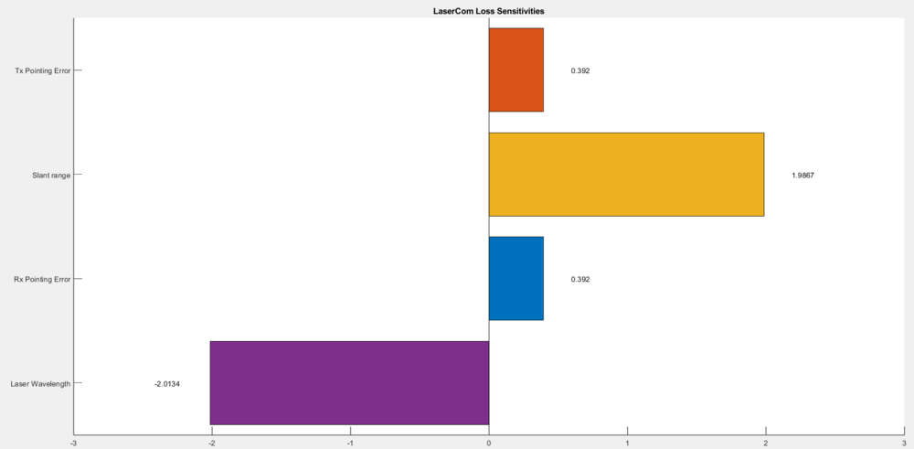
===Sensitivity Analysis 2: Lasercom Loss Variables=== | ===Sensitivity Analysis 2: Lasercom Loss Variables=== | ||
[[File:Sens2_3SLC.png|1000px]] | [[File:Sens2_3SLC.png|center|1000px]] | ||
Revision as of 05:39, 5 December 2023
Roadmap Creators: Ryan Little; Benjamin Kazimer
Time Stamp: 4 December 2023
Welcome to the Satellite Laser Communication Technology Roadmap.
- Technology Roadmap Identified as 3SLC - Satellite Laser Communication
- This indicates a Level 3, Individual-Technology Level Roadmap and describes the functions, uses, history, present, and future surround Laser (optical) Communication on Satellites.
Roadmap Overview
Satellite Laser Communication (LaserCom) is a method of transferring data through an optical link using an onboard high-power laser system. This breaks from the historically standard Radio Frequency (RF) communication that has been used for satellites uplink and downlink since their inception. While a modern day RF communication link is considered high performing in the 100 - 500 MegaBit per second (Mbps) downlink data rate, an optical link can outperform this by up to 4 orders of magnitude. The TeraByte InfraRed Delivery (TBIRD) from NASA and MIT Lincoln Labs was able to demonstrate a sustained downlink of up to 200 Gbps in 2023. Lasercom data transfer may occur via uplink: ground station to satellite, downlink: satellite to ground, or intersatellite links: satellite to satellite. However, this technology is not without its challenges and limitations. Namely, a direct and accurately pointed path is required from lasercom source to its destination terminal in order to establish a valid link. In high orbital period orbits, such as LEO this may only allow for a link lasting several minutes per period. However, even with this limitation Lasercom technology allows vastly higher communication data rates and total information transfer at 10-100x that of the more conventional radio frequency communications.
How it works: Lasercom utilizes the ability to create oscillations in light waves in lasers to pack a high data volume into the data beam waveform. In its simplest form, information is transmitted by modulating light and broadcasting it over some medium (wire or air). Following this logic, we understand the driving physical limitation is the frequency of the light; how much information can be encoded in modulation in a unit time. The higher the frequency of the light used, the faster the signal can be modulated and the throughput is increased. The defining disruptive aspect of optical communication is exactly this: a fundamental shift along the electromagnetic spectrum from radio waves to higher optical frequencies, yielding much larger data bandwidth possibilities.
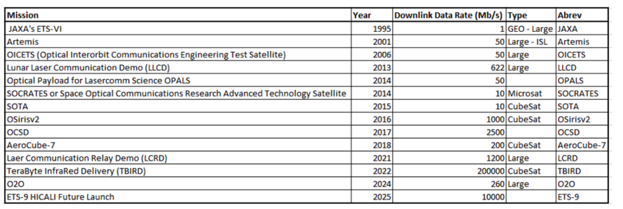
Advancement and proliferation of optical communication in space has enabled new capabilities that were previously not feasible due to data bottlenecking. As seen in the 2EOS roadmap, Earth observing imaging platforms are increasing in both spatial and spectral resolution. A key example is the Hyperspectral Imager Suite (HUSI) hosted on the ISS, which currently generates 300 GB of data per day. At this rate, the ISS cannot wirelessly downlink the imagery and data is currently transferred through hard drives on cargo ships! Current technology is also moving towards proliferated sensors rather than a few larger imagers, all greatly increasing the amount of raw data that needs to be transmitted to ground stations for processing and analysis. With all these trends, conventional RF communications can only be pushed so far and the need for lasercom terminals becomes apparent and necessary. Some RF transceivers have achieved appreciable data rates, such as the Integrated Solar Array and Reflectarray Antenna (ISARA) in 2017 at 100 Mbps, and some transmit only payloads can exceed that (Syrlinks EXC27 in 2015 at 140 Mbps), but they reach a practical limit in terms of SWaP when hosted on small sats. Optical payloads have steadily increased in proven data rates, from the JAXA ETS-VI at in 1995 1 Mbps, to Lunar Laser Communication Demo in 2010 at 622 Mbps, and more recently the Laser Relay Communication Demo in 2019 at 1.2 Gbps. This progress has recently culminated in the groundbreaking 200 Gbps link achieved by the NASA/MIT LL TeraByte InfraRed Delivery (TBIRD) lasercom terminal during a May 2022 flight test.
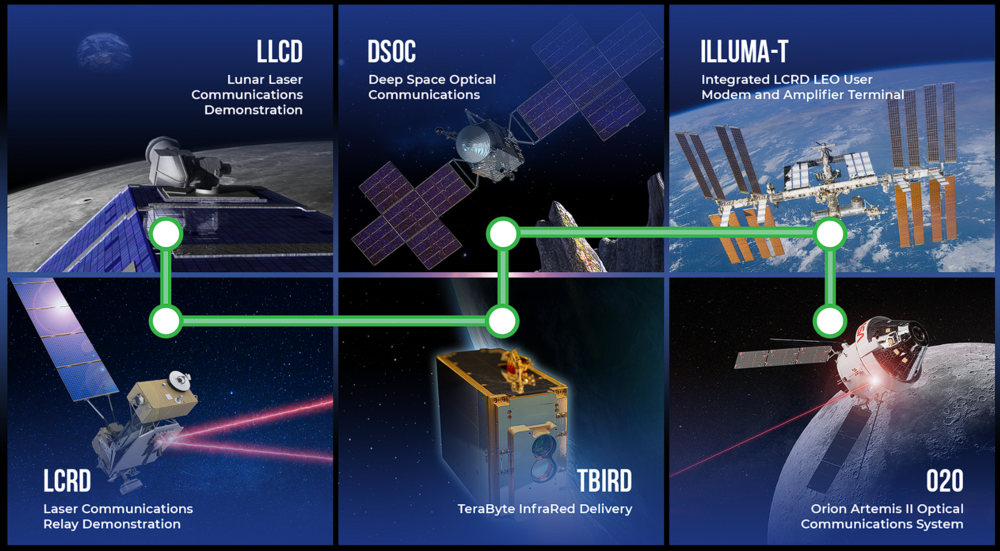
NASA's Official Laser Communication Relay Roadmap
Design Structure Matrix (DSM) Allocation
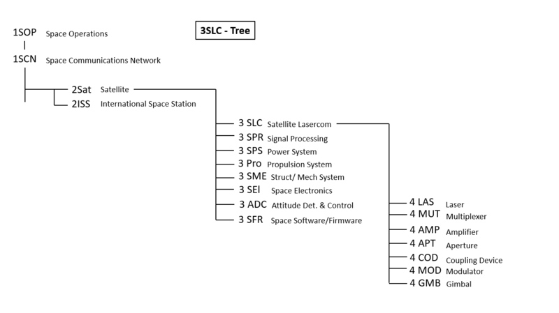
DSM Tree
The 3SLC-Tree that can be extracted from the DSM charted below serves as a good overview of a Satellite LaserCom’s functional placement among the broad level of technologies in space and how it lends itself to that network’s wide functionality and the specific hardware that enables satellites and lasercom itself. The tree shows that Satellite Lasercom (3SLC) is an Individual Level Technology that is a part of a larger Satellite (2SAT) Technology that lives within the highest-level Technology classifications of Space Operations (1SOP) and Space Communications Network (1SCN). Many other satellite subsystems exist at level 3 alongside Satellite Lasercom (3SLC) and comprise the satellite. Furthermore, many individual technologies are essential componentry to functioning Lasercom exist at Level 4. This tree highlights those specific technologies for LaserCom and not all the level 4 technologies that are necessary for other satellite subsystems. The DSM Tree is good to become familiar with to understand what technologies are present in the Lasercom conversation, before delving into the more detailed technological roadmap relationships and exchanges between these techs that are presented in the DSM chart.
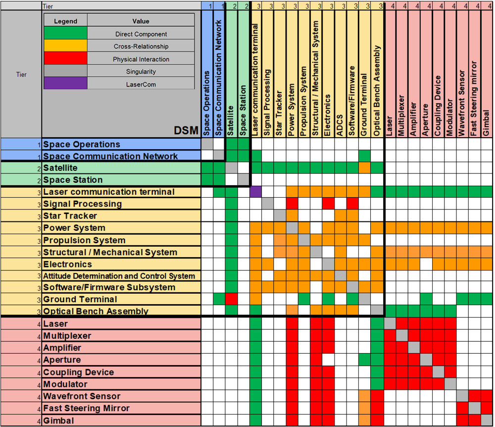
DSM Charting and Technology Relationships
DSM Chart
Power
The satellite Power Subsystem has interactions and supplies inputs to nearly all other fields in the DSM. This system and its budgets are therefore critical to the Satellite design holistically as well as critical at the LaserCom Level. One benefit of LaserCom, is that it can operate at relatively low power in comparison to a fully functional RF-based satellite system. So, while many of the same interactions occur, the lasercom reduces the allocated power budget for the communication system. The power savings from reductions can then be spent elsewhere (e.g. on-board processing) or maintained at a reduced overall value. An overall power reduction on a satellite often correlates to further reductions in mass and/or volume budgets as well. Therefore, a LaserCom system can be employed to generate a total SWaP reduction on a satellite (for more on the importance of SWaP, see FOM section).
LaserCom Tier 4 Componentry:
The Design Structure Matrix also provides access to the part-level componentry that makes up the LaserCom system. This Tier 4 componentry is common across satellite LaserCom systems and combined they provide access to the basic LaserCom functionality. The general individual functions of these components are as follows:
- Coherent (Optical) Modem – High-level assembly; optical transceiver that receives, modulates (digitizes) and processes optical signal.
- Laser – Provides the source “Beam” through which link is established and information is sent from the satellite/ground station to the receiving body for uplink/downlink/inter-satellite link. There may be multiple beams or “channels” per LaserCom system, and each can carry data. Large wavelength range available: typically. Note: Laser often is non-visible.
- Multiplexer – combines lasers from multiple lasers to achieve a higher power signal.
- Amplifier – increases laser link signal to help optimize critical signal-to-noise ratio, Eb/No.
- Coupling Device – Redistributes the number of optical signals by combining or splitting into a designated number of fiber optic inputs and outputs.
- Modulator – Modifies the polarization, phase, and/or power of a beam.
- Mirrors – Controls and redirects beam to other various components in optical assembly.
- Beam Splitters – introduces the ability to separate laser into two or more beam outputs.
- Wavefront Sensor – common ground station component that measures the phase and intensity inside the aberrations of the beam.
- Fast Steering Mirror – mechanized mirror system for higher accuracy and adaptable beam redirection. Used to minimize thermal expansion misalignment and introduce signal jitter control and reduction.
- Gimbal – a highly precise slewing, pointing system for achieving stringent laser pointing accuracy requirements that accompanies lasercom. (Sometimes not needed if satellite body-pointing can be made highly accurate e.g., TBIRD mounted on NASA PTD-3 with body pointing only.)
Roadmap Model using OPM
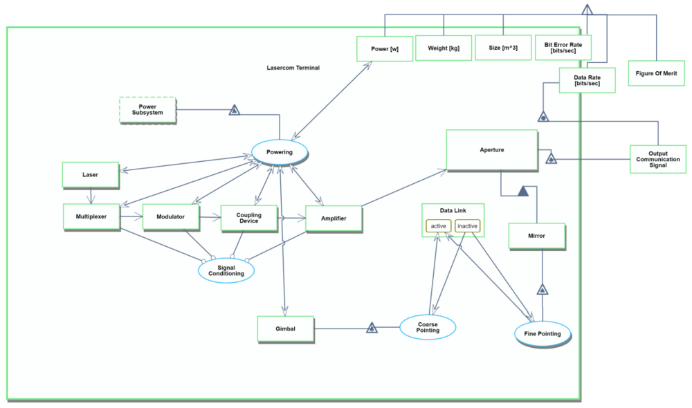
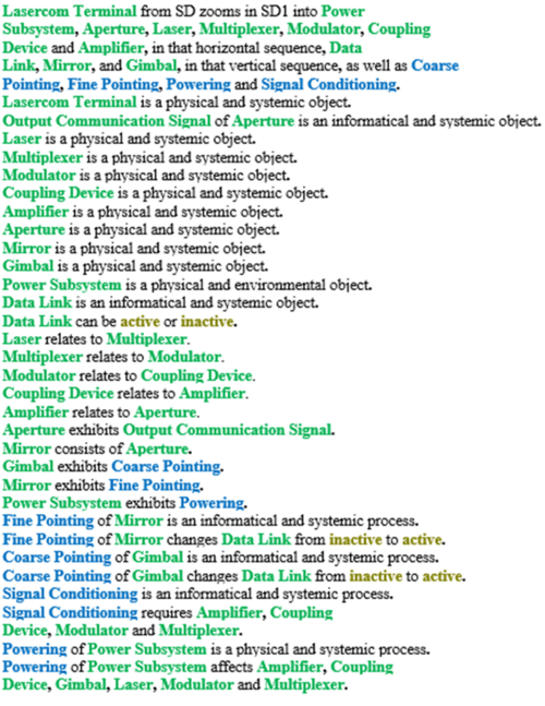
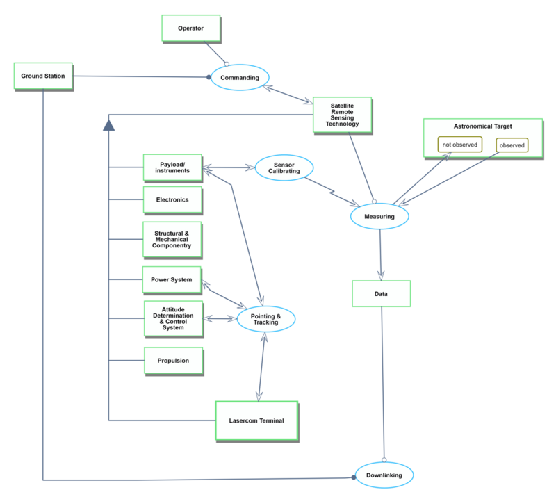
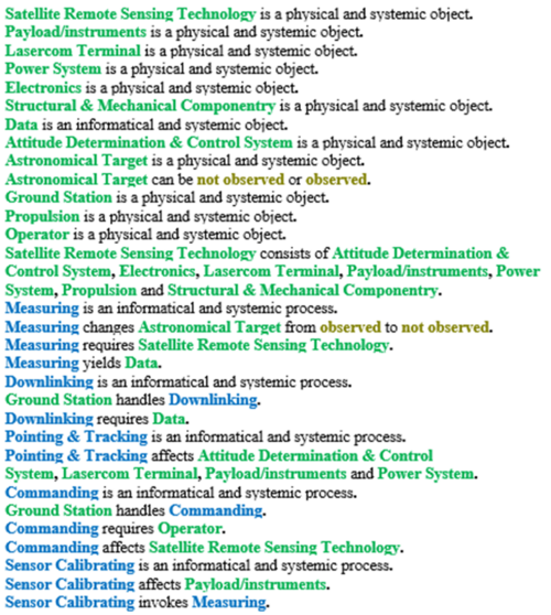
Object-Process-Diagrams (OPD) of the 3SLC roadmap is provided in the figure below. The first diagram captures the main object of the roadmap (Lasercom Terminal) and its enabling technologies and operational interactions. A higher level OPD is also included here to explain how the Lasercom Terminal fits and interacts at the Satellite Level (Satellite Remote Sensing Technology).
Lasercom Terminal Object Processes
When observing the lasercom OPM, it can be helpful to think of it in terms of three subsystems: signal conditioner, aperture, and gimbal. The OPM shows a basic signal conditioning chain starting at the source laser, which is encoding with information, conditioned, and amplified before passed through the aperture and out of the terminal. The aperture can contain many optical components to correctly point and steer the beam, while maintaining a coherent signal. Finally, the gimbal points the beam, terminal, or entire spacecraft to achieve the data link with the receiver station.
Note the figures of merit at the top right of the OPM. The data rate and bit error rate are directly related to the output communication signal, and indirectly to the signal conditioning chain. The power consumption is directly related to the power subsystem, while the weight and size FOMs connect to nearly all aspects of the terminal design. These FOMs will be discussed in greater detail in later sections.
Sensing Satellite Object Processes
The Sensing Satellite Level OPM, shows how the many Tier 3 Technology physical objects interact and comprise the Level 2 satellite to preform operations that allow the satellite to collect, process, and send/recieve data to/from the operational ground station. The informational and systematic processes here, display some of the interactions taking place between these technologies.
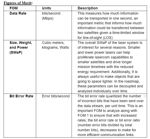
Figures of Merit
Key FOMs
The driving Figure of Merit for lasercom is data rate, particularly the satellite downlink data rate in which the satellite sends information it has collected to the ground station on Earth. A key motivator for pursuing the development of Lasercom technology is to create higher throughput data links in space, beyond what has been available through traditional radio frequency communications. Lasercom allows for a drastic multiplication of downlink data rates, for example a satellite operating at a ~100 mbps downlink is on order for a high performance RF DL link on a large satellite in the X-band and there are plans to attempt a 2 Gbps X-band link, while NASA and MIT Lincoln Labs TBIRD 6U CubeSat has used lasercom to demonstrate a 200 Gbps downlink. Albeit the comm window is much smaller as the satellite has much more precise pointing requirements and atmospheric conditions than RF comm payloads. Even amongst this more stringent communication window lasercom allows a program to collect 10x - 100x more data that of RF based satellite systems: https://www.nasa.gov/communicating-with-missions/lasercomms/ This multi-order throughput result drives the case of lasercom in the data rate figure of merit. It proves lasercom systems to be highly desirable satellite capability as it has opened up what has historically been a bottleneck of satellite information transfer through restricted communication capabilities.
To ensure the viability of lasercom for use on small satellites, the overall Size, Weight, and Power (SWaP) of the terminal are important FOM. System weight has been trending down over the years from advances in shrinking powerful lasers. Roughly 10 years ago, terminals were upwards of 6 kg with the NICT SOCRATES device yet nowadays payloads are reaching sub-kilogram specifications (DLR OSIRIS4). On the other hand, power consumption values have been consistent over the past decade, varying from <5 W (NICT VSOTA) to 100 W (TBIRD). Power can vary depending on the underlying laser technology and transmitting scheme and is closely related to other FOM for the link budget that can extend beyond the transmitting lasercom terminal. These link budget parameters include beam width, pointing accuracy, receiving telescope diameter, receiving terminal sensitivity, and bit error rate. Utilizing a simple link budget equation that folds in all the ground terminal and lasercom system parameters, along with atmospheric attenuation factors, one can model communication performance. This output can be used to perform sensitivity analyses, understand which link geometries are possible with different technologies, and identify which aspects to improve through investments and R&D.
Downlink Datarate vs Time and Datarate Modelling
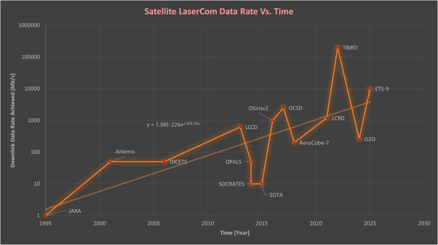
There has also been a significant increase in the capabilities of lasercom itself over the past 28 years, particularly in the achieved downlink data rate field. This progress has been captured (made by the date collected by the team) in the plot below, from various space missions since the first demonstration in 1995 from the JAXA program at 1 Mpbs to the 2022 demo of TBIRD at 200 Gpbs. Note the plot needs to be scaled logarithmically on the y-axis in order to distinguish the scale of progression in a readable format.
Modeling Rate of Improvement: While this timeline does a good job of creating an overall picture of the progress made in Lasercom both in rapidly improving optical data rate, dL, capabilities and increasing frequency of lasercom mission/investment of all satellite types, it is a bit tricky to model a representative δdL/δt due to the range of missions (demos, functional terminals, ect), satellite platforms, orbits and orbit/orbital altitude. Furthermore, the recent TBIRD demo is a serious outlier, it’s a promising sign for the future of lasercom and achievable dL, but it skews any form of least-squares regression fit to the model. However, an overall trendline and equation can be formatted pretty nicely to the logarithmic y-axis as shown below.
This trendline is modeled off of the exponential equation:
Since this is an exponential equation mapped to a logarithmic plot, it actually tracks well linearly and can be used to get a reasonable estimate of achieved average lasercom data rate at any given year. For example in 2016 it estimates a dL of 322 Mbps. Extrapolating this out to say 2030, yields an estimated average data rate of 1.23 Gbps. This is likely a reasonable estimate considering the TBIRD demo tech follow ups are looking to place many TBIRD-based terminals on future missions in the coming years.
Lastly, the derivative of Eq. 1 can be taken to get the instantaneous δdL/δt of this trendline. Calculating this derivative (which is actually super easily for e^x, just apply chain rule) yields:
This equation can be used to calculate the instantaneous rate of change for downlink data rate via lasercom at any given year. For example at year = 2022, δdL/δt is 398.4 Mbps, but as this technology continues to progress into the future at year = 2025, this model predicts δdL/δt to be 869.1 Mbps.
Alignment with Company Strategic Drivers
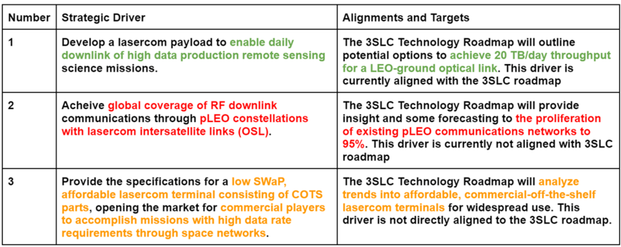
The table below outlines high level satellite laser communication strategic drivers and their alignment with the 3SLC Technology Roadmap:
As mentioned throughout the 3SLC roadmap, the continued advancement of satellite laser communication capabilities will enable entirely new markets of work. One prevalent application is the downlink of data from remote sensing platforms on orbit. NASA Surface Water and Ocean Tomography (SWOT) launched in late 2022 generates roughly 20 TB of data per day. Current RF and even lasercom communications capabilities cannot support the daily downlinks of this size, but it serves as a target point for future design. The driver can be split into two targets: one being the physical upscaling of current technology while the other is more aligned with advancing current data rate capabilities. For the former, we assume TBIRD capabilities at 4.8 TB data throughput per day from Paper 2 in the Key Publications section (this encapsulates pass window timing, data rate, and losses). As SWOT is a large class satellite, one could formulate the idea of stacking 4 or 5 TBIRD-like terminals on the bus to transmit down all data generated per day.
For the technological development pathway to align with driver 1, one can instead back out the necessary data rate achieved by one module. Assuming a nominal daily pass window of 6 minutes, the required average data rate to transmit 20 TB of data is 926 Gbps. Using the FOM model from the FOM section of this roadmap, the predicted year to achieve this data rate is around 2046. It is worth noting this figure comes from a Moore’s Law assumption and it is projected the technology might follow a Pareto Front progression as the COTS industry catches up. This behavior could lead to near Tbps data rates by the early 2030’s.
Strategic driver 2 encompasses the proliferation of lasercom terminals on satellites in a large volume communication network, such as SpaceX's Starlink. These terminals would act as intersatellite links (ISL) for the transmitting of information between satellites to decrease end-to-end latency of beyond line of sight (BLOS) communication links across the Earth. This is a unique LEO-LEO link geometry that enables the relay of information across nodes to rapidly connect ground terminals on opposite sides of the globe. As briefly mentioned in the literature review section, roughly 45% of current Starlink satellites have the hardware to support this relay but the actual performance of ISLs is unreliable (September 2023). SpaceX predicts that by 2026, this modality will be stable through software updates and continued launches of improved hardware. Given the lack of public information and uncertainty surrounding this capability, the 3SLC roadmap is not aligned with this strategic driver, but is an important target for the future of lasercom.
The third strategic driver targets low SWaP-C lasercom terminals that primarily consist of COTS hardware. The streamlining and mass production of such a terminal design would allow for simple integration into systems that would benefit from high data rate communications, primarily in the civil market. Companies would be able to leverage proven and reliable communications hardware, leading to faster integrations and enabling new missions. Similar to strategic driver 1, these new markets include high data throughput applications such as high resolution imaging, but could be extended to smaller volume LEO communication networks, climate sensing, and relay nodes for beyond LEO communication links. This driver is not directly aligned with the 3SLC roadmap, but there is discussion on emerging technologies that could fill this demand such as the CubeCAT terminal currently in development by AAC Clyde Space. As all the underlying critical hardware components that enable lasercom continue to mature, it is inevitable that more mass produced COTS products will enter the market.
Positioning of Company vs. Competition
Shown below is a technical specification overview for modern laser communication terminals designed for use on satellites, along with some example images:
Note: Entries containing "---" indicate the information could not be found through public access, whether it is intentionally withheld for existing systems or not yet determined for future programs.
The key FOMs in the table are data rate, power consumption, and terminal mass. Also included are relevant parameters beam wavelength, modulation scheme, link geometry, and platform class. The FOM section of this roadmap covers dedicated discussion and the modeling of data rate over time, the single most important FOM for characterizing the progress of lasercom technology. Ideally, the data rate would constantly increase over time but the dimensionality of the problem increases when different use cases are considered. Interesting results can be seen when the data rate is analyzed in a coupled sense with the link geometry or platform class, yielding insight to specific mission areas and applications. As seen in the technical model section, data rate is proportional to the transmit power of the laser (Pt) and follows an inverse square relationship with distance (L) between the transmit and receive nodes. The first relationship influences the application space of hosting lasercom capabilities on smaller satellite platforms, showing the need for efficient laser technology in a SWaP constrained environment. The proposed CubeCAT terminal fills this niche with a small but relatively efficient laser for cubesat operations in LEO. CubeCAT makes highspeed lasercom accessible for smaller platforms that will be stationed close to Earth. On the other side of the tradespace is the HICALI technology, designed for GEO operations on a larger satellite platform. HICALI provides an impressive 10 Gbps data rate but draws the highest power of all mentioned terminals, due to its orbital distance being 100x that of LEO operations. Both HICALI and CubeCAT are important technologies for enabling high speed communications in vastly different application spaces.
A less common lasercom application is the use of a transmit/receive terminal in LEO that can relay signal from the Earth to GEO, lunar orbits, or even into deep space. This is a much lower volume market that LEO-ground connections or ISL terminals, but serves an important role in the area of space exploration. As humans travel back to the moon, set foot on Mars, and travel beyond, connecting signals through a LEO node leads to less taxing requirements on the data rate link budget and error rate tolerances. Technologies such as ILLUMA-T are addressing this niche market for scientific purposes, but it is worth noting the concept of LEO-GEO lasercom connections could become a worthy area for commercial expansion in the near future.
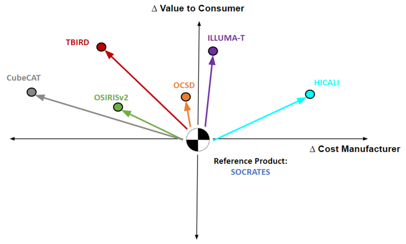
Vector Chart
To illustrate the progression and development of satellite lasercom technology, a vector chart was populated with the R&D projects discussed above. The SOCRATES mission was selected as a baseline, being the earliest technology in this analysis. Many of the systems focus on LEO-Ground links, and are stronger comparisons with the baseline. The Aerospace Corporation-made AeroCube-7-OCSD showed improvements in all FOM over that of the baseline, leveraging recent advancements in smaller, more efficient technologies. Through the flight test of OsirisV2 by DLR, a higher data rate was accomplished on a much smaller platform (NanoSat class). The small form factor and higher data rate prove to be valuable to the customer, opening up new communication capabilities without the system occupying much bus space. This roadmap contains much discussion on TBIRD but the relevant points for this comparison are emphasis on very high data rates and low-cost production with primarily COTS parts to increase value. The proposed CubeCAT terminal is looking to take key aspects of the two previous projects with a high data rate output from a NanoSat class payload. Targeted for high volume production, this asset is meant to drive down production cost while provided competitive performance.
The last two technologies focus on less common data links between the platform and receiver. These domains inherently lead to higher production costs, but both (ongoing) research efforts will prove valuable to a different market if successful. The HICALI system will aim to transmit between GEO-Ground, a valuable link for larger, more expensive satellites in GEO. We see this technology providing high data rates with a large, high power payload, a necessary trade to establish links at such great distances. Lastly is NASAs ILLUMA-T technology, a terminal that will transmit data from LEO, to a relay station in GEO (LCRD), finally to ground terminals on Earth. The incorporation of a relay makes this case difficult to compare with the baseline as we are essentially approaching a network in the former, but the value here comes from the bestowed freedom on the host platform. In the case of ILLUMA-T, the host is the ISS, a spacecraft that cannot point and orient itself to support the communications payload. The relay through a stationary platform in GEO allows for more consistent communications and less stringent pointing requirements.
Technical Model
Morphological Matrix
Shown below is a morphological matrix for satellite laser communication. This table can be used to map trends in design choice across key technical parameters related to this technology:
Sensitivity Analysis 1: EIRP and Data Downlink
To analyze the effects of various LaserCom FOMs on the critical Downlink Rate [mbps] metric, consider the Laser Link Equations and Effective Isotropic Radiated Power (EIRP) [W]. This term measures the laser power emitted from the satellite and is often defined (including at MIT) as EIRP = P*G, where P is transmitter power and G is aperture gain. These variables fold into the main dictating downlink date rate equation:
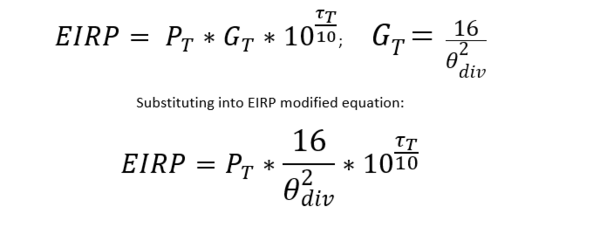
This sensitivity analysis will analyze the EIRP inputs to the downlink equation, while also folding in optical losses τT [db] and beam divergence angle Θdiv [rad], into the equation and create a modified EIRP equation:
This is the governing equation that will be analyzed and normalized to calculate the sensitivity of downlink data rate for inputs Power [W], Beam Divergence [rad], and Optical Losses [dB]. These sensitivities will be analyzed at vector x0, which is based on values of the FOM metrics pulled from the TBIRD Mission and are included below:
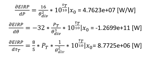
To start the analysis, the partial derivates relative to each of the variables whose sensitivity will be analyzed must first be taken and then analyzed for a non-normalized value at vector x0. Yielding the following results:
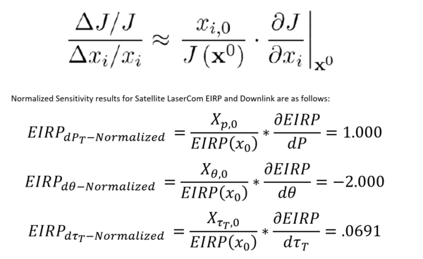
These are the instantaneous values partial differential values of each FOM being analyzed against EIRP, however they are currently non comparable values because they have not been normalized against one another. These must now be normalized based on the following mathematical definition (see full results in MATLAB output in appendix):
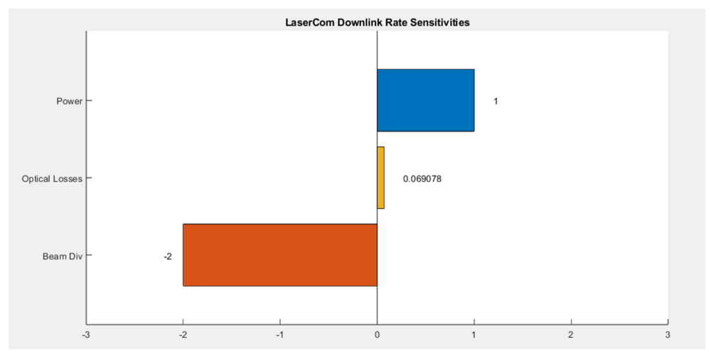
Plotting these results into a tornado chart, yields the following:
These results show the relative, normalized sensitivity of EIRP and therefore downlink data rate have to the Power, Beam Divergence, and Internal Optical Losses design FOMs. They show that of these figures of merit, the Downlink achieved is most sensitive to the beam divergence Θdiv. This value is negative because it varies inversely with EIRP, it also levies twice the effect of PT on EIRP, because the Θdiv term is squared. The other terms have positive normalized sensitivities because they vary more directly (in the numerator) with EIRP. The Laser Transmitter Power PT is the second most sensitive. The variation in internal optical losses τT has the least effect on EIRP and Downlink Rate when evaluated at design vector x0. This occurs mathematically because of its fractional dB value in the exponential term in the EIRP equation. These sensitivity values and charts are particularly useful to informing the LaserCom terminal design. Pinpointing a minimal Θdiv and maximizing PT allows will allow the EIRP to reach a max and maximize the LaserCom terminal design all else equal. Some fine tuning can be done by keeping optical losses to a minimum, but shouldn’t lead the design effort as a primary target.
Sensitivity Analysis 2: Lasercom Loss Variables
Financial Model
NPV Analysis
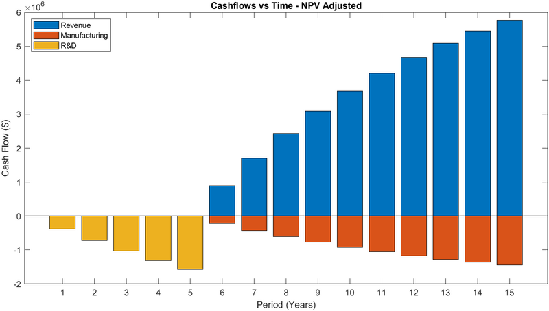
The approach used for this Net Present Analysis was to estimate the monetary inputs for a research facility demo-ing and prototyping a total of 10 satellites based around Lasercom was to reference the recent Starlink program itemized costs for their constellation of 5000+ and counting satellites. Basing R&D and Manufacturing/Maintenance costs and Revenues from Starlink and normalizing the costs to a per satellite unit price, offers a nice first order approximation for the inputs to a Lasercom Satellite NPV analysis. These basic cost values could then be coupled with Smallsat and Low Earth Orbit specific input values that are representative of an early LaserCom Demo and tech transfer initiative from a FFRDC such as Lincoln Labs or JPL to better replicate a Mission such as TBIRD (the mission often referenced elsewhere in this roadmap). The unitized input values used for the first NPV analysis were as follows:
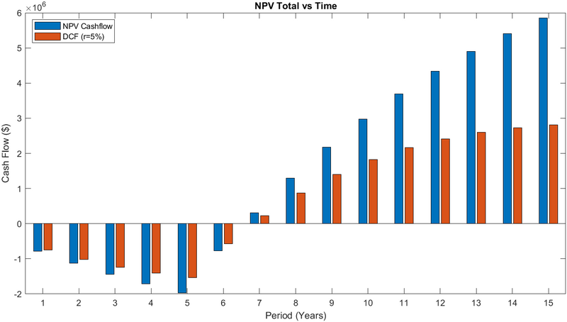
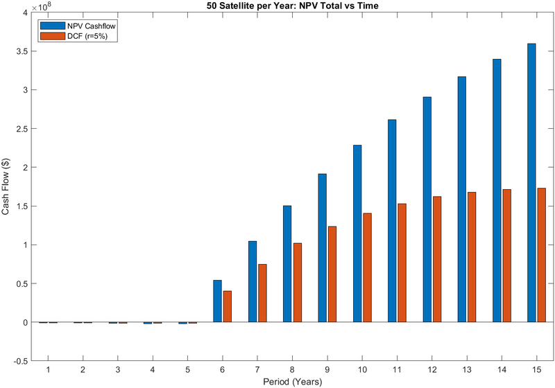
Applying these inputs, rendered the following calculate and plotted results for NPV Normalized cashflow at a 5% discount rate and Total NPV and Discounted Values:
This analysis yields these NPV output values:
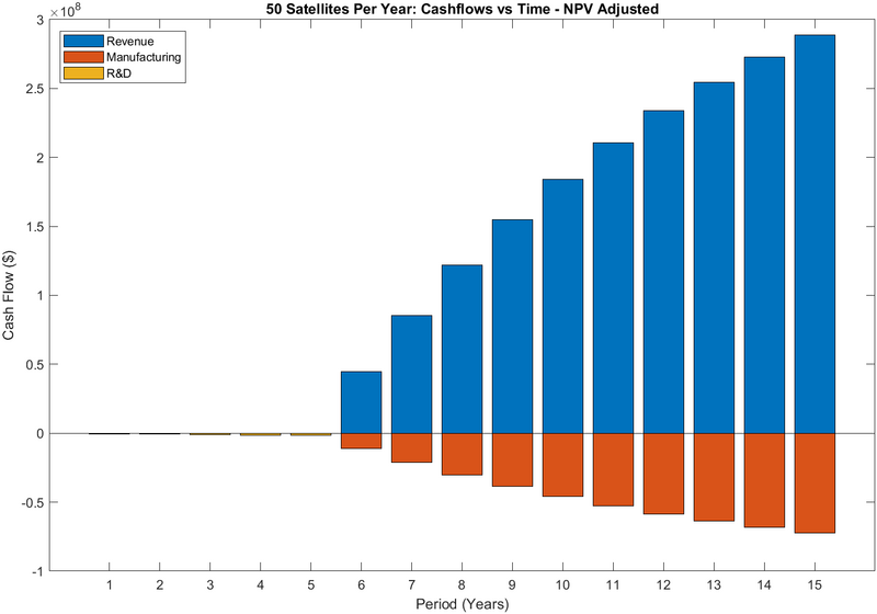
This analytical approach for modelling NPV can then be extrapolated to be representative of a Satellite manufacturing company, rather than a research facility in the prototyping phase. To do this, the number of satellites input must be modified to sat = 50 Satellites to be more representative of the different business model and strategic aims of a for-profit business. This will also show that the NPV and the NPV/sat are greatly improved with this approach as the revenues eclipse the non-recurring costs of initial R&D investment. These Modified results are included below:
This analysis yields these NPV output values:
In the satellite manufacturing model, the NPV per Satellite increases over tenfold to $7.2 million with a total Net Present Value of $359 Million. NPV adjusted revenues total to $300 million by the end of the 15-year period for the total of 500 satellites in operation. This is on order with that of the further upscaled production of Starlink Model, which is projecting ~$6 billion in Revenue for their 5000 Satellites and predicted NPV by 2025 of $10 - 35 billion (range dependent on user adopter rate confidence interval, https://pubs.aip.org/aip/acp/article-abstract/2549/1/200002/2903468/Economic-model-of-costs-required-to-create-and?redirectedFrom=fulltext)
Research and Development (R&D) Projects
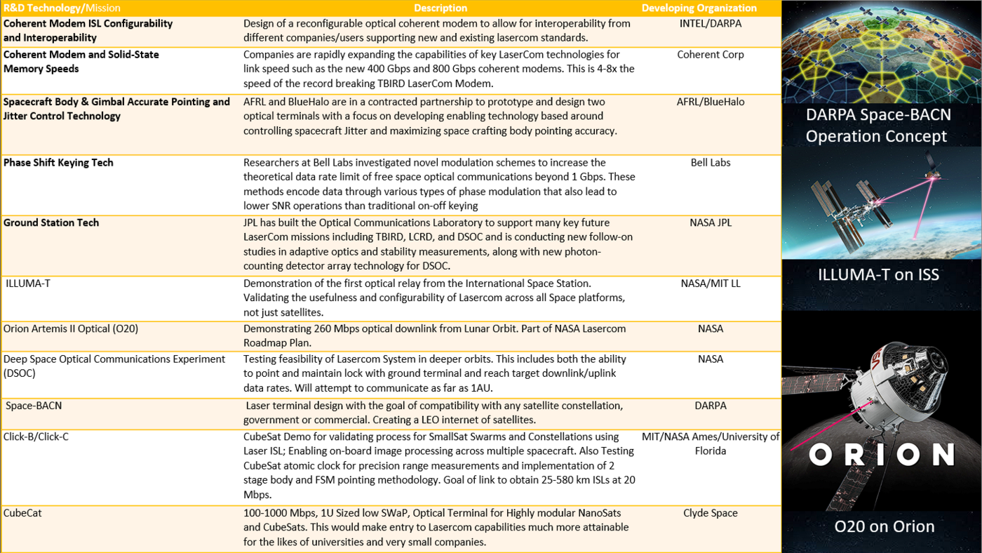
In the interest of predicting the future expansions and improved capabilities of space-based LaserCom, a set of Space Optical technological research endeavors and specific LaserCom-based missions have been flagged for the roadmap and organized below. These include new processes and products from companies and research facilities in the Advanced R&D and Breakthrough level technology that are still in development. It also is comprised of missions such as TBIRD and ILLUMA-T that have launched as optical experiments and are currently or about to undergo testing to demonstrate new applications of Lasercom technology. These various Projects and Missions are described and then parsed into an R&D Framework.
Research Technology Table
R&D Framework
Key Publications, Presentations and Patents
Patent Review
Patent 1: 20200169323 System And Method Of Satellite Communication HO4B / H04L
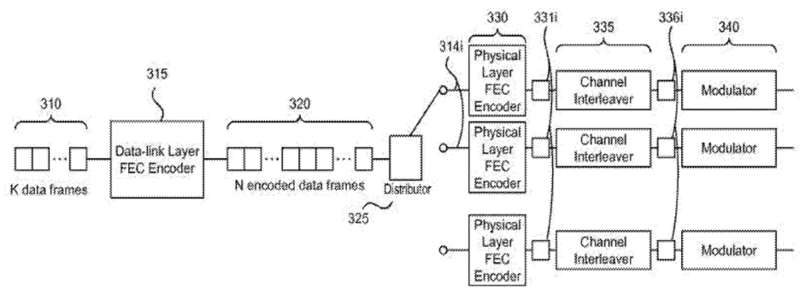
This patent discusses the layering of data link and physical systems to achieve high data rate (1 Tb/s) lasercom links that are generalizable to space-space, space-ground, and ground-ground. An interesting aspect of this work is that the patent holder is Facebook Inc. (now Meta), and presented to have applications in global wireless internet coverage through a communication network consisting of optical links connecting satellites and ground stations around the Earth. Error correction processing is incorporated throughout the proposed transmit receive (TX/RX) terminal architecture, ensuring the high speed data links successfully transmit their designated information. The image below shows the encoding scheme that allows the multiplexing of information through a multi-channel lasercom signal.
Image credit to patent US 2015/0349881 A1
Patent 2: 20220303009
Free-Space Optical Communication System And Methods For Efficient Data Delivery
HO4B / H04L
This patent covers advances in the optimization of data links for space based laser communicatio, specifically from members involved with the TeraByte InfraRed Delivery lasercom module being developed at MIT Lincoln Laboratory. The work outlines the use of high speed optical modems with an automatic repeat request (ARQ)architecture that enables error-free 100 Gbps Low Earth Orbit to ground data links. A key aspect of the novelty and relevance of this patent to the field of lasercom is the automatic repeat request error checking algorithm, which utilizes a secondary, low data rate link to ensure sequential data chunks are properly received before reading in the next chunk. This removes the need for any operator in the loop and results in efficient, automatic data transfers during the overhead satellite pass. The bottom portion of the figure below highlights the uplink/downlink for a lasercom signal, including the novel ARQ blocks on both end for error correction.
Image credit to patent US 2022/0303009 A1
Patent 3: 20150349881
CONTROL SYSTEM FOR MULTI-BEAM FREE SPACE OPTICAL ENDPOINT
H04B
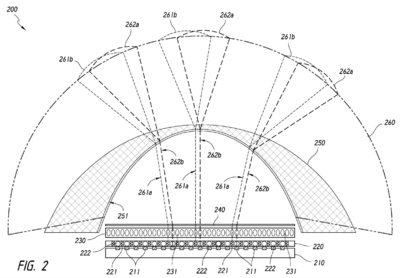
This patent proposed an interesting lasercom architecture that leverages a plurality of devices for multiple communication link endpoints. The system utilizes mechanical steering of transceiver modules and active beam deflectors to track moving transmit/recieve terminals. The underlying engineering design found in the patent has many applications for ground based communications, while the novel tracking aspect can naturally be extended to space applications. This patent is relevant to satellite based lasercom by incorporating these mechanical features into ground stations that can more accurately track overhead satellite passes, acting as a secondary steering mechanism along with the bulk motion of the primary telescope. The below figure from this patent represents a multi-input receiver ground station that can decode information from multiple downlink platforms, increasing bandwidth, flexibility, and throughput for large communication networks.
Image credit to patent US 2015/0349881 A1
Literature Analysis
Publication 1
Guelman, M., Kogan, A., Kazarian, A., Livne, A., Orenstein, M., Michalik, H., and Arnon, S., “Acquisition and pointing control for inter-satellite Laser Communications,” IEEE Transactions on Aerospace and Electronic Systems, vol. 40, Jul. 2004, pp. 1239–1248.
Throughout this roadmapping, it has become prevalent that satellite lasercom requires great advances in low SWaP laser technology as well as controlled and precise spacecraft attitude control. A key difference between traditional RF communications and lasercom is the directionality. RF waves can be broadcast across +120 degrees FOV, easing requirements on bus pointing control during communication links. On the other hand, lasers will need thousanths or ten thousandths of a degree precision for pointing. This paper proposed a robust technique that relies on a gimbaled head to point the transceiver while a closed control loop works to alter the laser beamwidth and directionality through fine steering mirrors located in the optical assembly. This paper focuses on the application of this method to intersatellite communications, a necessary connection to enable networks like those covered in Patent 1. It is worth noting this paper is relatively old in the field being published in 2003, and the proposed architecture requires either an existing data link to close the loop and establish the data link, or the authors propose mounting retro-reflectors on the buses as a feedback mechanism to the partner satellite. That being said, this paper is still relevant due to its progress in intersatellite data links which are a key factor in the ever growing number of satellites in proliferated networks.
Publication 2
Riesing, K., Schieler, C., Bilyeu, B., Change, J., Keer, B., Tarif, A., Piazzolla, S., Wange, J., Robinson, B., Reeve, R., Horvath, A., Gilbert, N., and Garg, A., “Operations and Results from the 200 Gbps TBIRD Laser Communication Mission,” 37th Annual Small Sat Conference, Aug. 2023.
As mentioned in our roadmap and called out in review 1, the TeraByte InfraRed Delivery (TBIRD) lasercom module has revolutionized the field of satellite based lasercom. In its 2022 flight test, TBIRD exhibited a 200 Gbps data rate and 4.8 TB throughput. This data rate was a 2 order of magnitude improvement over the existing state-of-the-art LEO-ground data rate of 1 Gbps achieved by the DLR OSIRISv2 program in 2016. As discussed in Patent 2, TBIRD accomplishes this revolutionary performance with high speed optical modems and automatic repeat request error checking algorithms. This paper provides more detail into the 2022 flight test, paving the way for the community to continue towards Tbps data rate capabilities. As discussed in the paper’s intro, this data rate not only optimizes current communication needs, but enables completely new science missions that generate high volume data products such as hyperspectral imagers, synthetic aperture radars, and radiometers. TBIRD is a disruptive technology in its own field, creating access to new markets in space based remote sensing.
Publication 3
Boroson, D. M., Robinson, B. S., Murphy, D. V., Burianek, D. A., Khatri, F., Kovalik, J. M., Sodnik, Z., and Cornwell, D. M., “Overview and results of the Lunar Laser Communication Demonstration”, Free-Space Laser Communication and Atmospheric Propagation XXVI, 2014.
One key market that lasercom is poised to overtake conventional RF communications is that of deep space data links. This publication outlines the first successful two-way lasercom link between terminals across lunar orbit and on Earth, proving out technologies that will lead to even further data link distances to Mars and beyond. At a mission level, the relevance of this publication is profound in terms of establishing the data link, but one can zoom into the technologies and analyze all the progress needed to enable that success. The lasercom terminal in this mission utilized a 15 microradian communication beam that had to be steered to an ~80 cm square revecieving telescope 385,000 kilometers away! Combining orbital knowledge of the lunar satellite and extremely precise uplink acquisition method, the low rate uplink could be established and lead to the even more precise alignment of the transmit beam to the ground telescope.
Seen below is the publication history trend of "Satellite Laser Communication" taken from Google Scholar. Notable features in the history come from revolutionary lasercom projects being launched and published on. The spike in 2006 was a result from the first LEO ISL demonstration with the OICETS program operated by JAXA. The bump in 2010 came from prelaunch planning and analysis of NASA's LLCD after the contract was awarded and preliminary findings were published. Into the late 2010s, publications were rapidly increasing and the field hit 100 publications/year in 2019, the same year project TBIRD was announced and preflight analyses were shared with the community. Overall, the recent boom in articles is a promising sign for the field as satellite lasercom technology progresses from an early demonstrator to a mature R&D capability.
In The Media
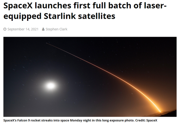
For the past three years, SpaceX has been integrating newer satellites into the StarLink pLEO constellation with up to four lasercom terminals to support intersatellite links (ISL). These optical links enable the rapid transmitting of information between satellite buses in the network, greatly reducing end-to-end latency. Currently, roughly 45% of the satellites in StarLink are equipped with lasercom terminals and that figure is expected to grow as more updated models join the orbit.
Technology Strategy Statement
Laser communication is revolutionizing the field of space-based communications, providing high speed, reliable, and secure data links both in space and to ground stations. Advancements in critical technologies, specifically optical modems and waveform encoding schemes, are enabling the rise of completely new markets that require high data throughput: high resolution remote sensing, inter satellite links for communication networks, and deep space data transfers.
This roadmap highlights key technologies and exemplar projects that continue to advance the state of the art capabilities. Looking into the future progression of this technology, this roadmap targets a lasercom system that can downlink 20 TB of data per day (Strategic Driver 1) while considering low SWaP-C qualities for widespread integration of this communication system (Strategic Driver 3). The first R&D project is the continued investment in the maturation and radiation hardening COTS hardware through a partnership with Cisco Systems to advance their +100 Gbps Quad small Form-factor Pluggable optical module. This hardware is critical for achieving high data rates with a lasercom system, and will contribute to both goals previously listed. The second funding proposal is for a flight test of stacking 4 lasercom modules on a large class satellite to push the limit of data throughput, and test the capacity of ground terminals. This project will help identify the limiting factors in extremely high data rate transfers and prove out capabilities for large satellites which will enable relay networks between Earth, space stations, and lunar bases.
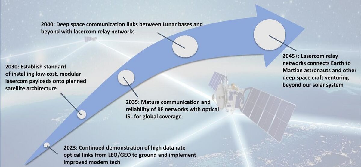
Background Image Credit: https://spacenews.com/military-agency-praised-for-leading-the-way-on-laser-communications/
2023: Taking lessons learned from demonstrated pathfinding projects such as high data rate throughput with TBIRD and a successful demonstration of lasercom relays from space to ground with ILLUMA-T, lasercom projects transition from Demonstrators to R&D and enter production. Targeting consistent +1Gbps data rates.
2030: Equipped all appropriate satellites with matured lasercom terminals is now the standard for communications practices. These terminals are reliable, low cost, and maintain less than 3U volume. This practice has opened the demand for a distributed network of ground sites across the world, expanding the market for mass producing receiving optics and creating jobs for ground station operators.
2035: RF-downlinking communications satellite networks have been proliferated with optical ISLs. This allows for fast and reliable communications between any two points on Earth. Along with the hardware, these networks are driven by advanced processing and scheduling algorithms that coordinate and optimize all communications between satellites and ground stations.
2040: Beyond Earth’s orbit, lasercom is used to connect our networks to semi-permanent research stations on the lunar surface and in its orbit. This enables video conferences (with a ~2 second lag) and high speed data transfers for effective research collaboration.
2045+: As more spacecraft and eventually humans are sent to Mars, lasercom connections are essential to share data through multi-node relay networks. At this point, all deep space probes and research craft utilize lasercom for extrasolar communications, also leveraging relay nodes throughout the solar system.
Learn More
References
[1]Williams, D., “RF and optical communications: A comparison of high data rate ... - core,” NASA Available: https://core.ac.uk/download/pdf/10536487.pdf.
[2]Schauer, K., “NASA Laser Communications Innovations: A timeline,” NASA Available: https://www.nasa.gov/missions/tech-demonstration/nasa-laser-communications-innovations-a-timeline/.
[3]“Laser Communications Relay Demonstration (LCRD) overview,” NASA Available: https://www.nasa.gov/directorates/stmd/tech-demo-missions-program/laser-communications-relay-demonstration-lcrd-overview/.
[4]“The nobel prize in physics 2023,” NobelPrize.org Available: https://www.nobelprize.org/prizes/physics/2023/press-release/.
[5]“9.0 communications,” NASA State of the Art Report Available: https://www.nasa.gov/smallsat-institute/sst-soa/soa-communications/.
[6]On-orbit demonstration of 200-Gbps laser communication downlink from ... Available: https://ntrs.nasa.gov/api/citations/20230000434/downloads/Schieler%20paper%20spie2023-tbird-v4.pdf.
[7]“Laser Communication in space,” Wikipedia Available: https://en.wikipedia.org/wiki/Laser_communication_in_space.
