Difference between revisions of "Energy Storage via Battery"
| Line 15: | Line 15: | ||
==Design Structure Matrix (DSM) Allocation== | ==Design Structure Matrix (DSM) Allocation== | ||
[[File:Assignment2DSM. | [[File:Assignment2DSM.JPG]] | ||
Our technology of interest is identified in the DSM above with green highlighting. it is portrayed in the context of the consuming technology of interest, electric vehicles, where we identified the typical consuming technology systems for reference. The diagram on the right is a dependency tree that has been extracted from the DSM. The battery storage technology consumes technology related to battery chemistry, including cathode, anode, catalyst, and semi-permeable membrane technologies. Battery technology also consumes technology related to the design of the shipping, manufacturing, material supply chain, and internal circuitry technologies | Our technology of interest is identified in the DSM above with green highlighting. it is portrayed in the context of the consuming technology of interest, electric vehicles, where we identified the typical consuming technology systems for reference. The diagram on the right is a dependency tree that has been extracted from the DSM. The battery storage technology consumes technology related to battery chemistry, including cathode, anode, catalyst, and semi-permeable membrane technologies. Battery technology also consumes technology related to the design of the shipping, manufacturing, material supply chain, and internal circuitry technologies | ||
Revision as of 17:55, 6 October 2019
Technology Roadmap Sections and Deliverables
The first point is that each technology roadmap should have a clear and unique identifier:
- 2SEA - Solar Electric Aircraft
This indicates that we are dealing with a “level 2” roadmap at the product level (see Fig. 8-5), where “level 1” would indicate a market level roadmap and “level 3” or “level 4” would indicate an individual technology roadmap.
Roadmap Overview
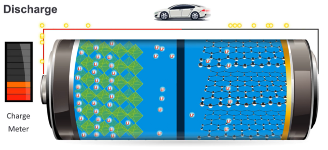
The working principle and architecture of an electrical battery are depicted in the below.
An electrical battery can store and use energy by chemical reaction. It is composed of an anode (-), a cathode (+), the electrolyte, and separator. The chemical reaction is a redox reaction caused by an electrical difference between the anode and the cathode. That is, electrons are expelled from the anode to the cathode via an external circuit and metal ion in the electrolyte receives the electrons on the cathode. This redox reaction lasts until electrical equilibrium. Although the primary battery is designed to be used once and discarded, the secondary battery can be recharged with electricity and reused. First secondary batteries based on Ni/Cd and Pd-acid were produced around 1900. After that, Ni/Zn battery which showed higher specific density appeared in the 1950s. In 1990, Lithium-ion battery (LIB) which is a major rechargeable battery today was released. The capabilities of LIB such as specific density, volumetric density, and cycle durability have improved more and more by developing new materials and the energy price is going down. These trends contribute to the growing availability of Electric vehicles.
Design Structure Matrix (DSM) Allocation
Our technology of interest is identified in the DSM above with green highlighting. it is portrayed in the context of the consuming technology of interest, electric vehicles, where we identified the typical consuming technology systems for reference. The diagram on the right is a dependency tree that has been extracted from the DSM. The battery storage technology consumes technology related to battery chemistry, including cathode, anode, catalyst, and semi-permeable membrane technologies. Battery technology also consumes technology related to the design of the shipping, manufacturing, material supply chain, and internal circuitry technologies
Roadmap Model using OPM
We provide an Object-Process-Diagram (OPD) of the 2SEA roadmap in the figure below. This diagram captures the main object of the roadmap (Solar-Electric Aircraft), its various instances including main competitors, its decomposition into subsystems (wing, battery, e-motor …), its characterization by Figures of Merit (FOMs) as well as the main processes (Flying, Recharging).
An Object-Process-Language (OPL) description of the roadmap scope is auto-generated and given below. It reflects the same content as the previous figure, but in a formal natural language.
Figures of Merit
The table below show a list of FOMs by which solar electric aircraft can be assessed. The first four (shown in bold) are used to assess the aircraft itself. They are very similar to the FOMs that are used to compare traditional aircraft which are propelled by fossil fuels, the big difference being that 2SEA is essentially emissions free during flight operations. The other rows represent subordinated FOMs which impact the performance and cost of solar electric aircraft but are provided as outputs (primary FOMs) from lower level roadmaps at level 3 or level 4, see the DSM above.
Besides defining what the FOMs are, this section of the roadmap should also contain the FOM trends over time dFOM/dt as well as some of the key governing equations that underpin the technology. These governing equations can be derived from physics (or chemistry, biology ..) or they can be empirically derived from a multivariate regression model. The table below shows an example of a key governing equation governing (solar-) electric aircraft.
