Difference between revisions of "Space Booms"
| Line 39: | Line 39: | ||
Based on the displayed FOMs, our team can define our strategies, set targets for success, and then use our roadmap to determine if they are feasible now or require patience before execution. The below chart depicts the strategies we considered, the targets associated based on roadmap FOMs, and whether or not they are currently viable: | Based on the displayed FOMs, our team can define our strategies, set targets for success, and then use our roadmap to determine if they are feasible now or require patience before execution. The below chart depicts the strategies we considered, the targets associated based on roadmap FOMs, and whether or not they are currently viable: | ||
[[File:FOM Strategic Drivers.jpg| | [[File:FOM Strategic Drivers.jpg|frame|Strategic Drivers]] | ||
Strategic driver number one is an effort to compete in the commercial composite spoolable boom arena. Given the existing material properties, market costs, and recent NASA research into boom geometry, we believe we can outpace current commercial efforts. | Strategic driver number one is an effort to compete in the commercial composite spoolable boom arena. Given the existing material properties, market costs, and recent NASA research into boom geometry, we believe we can outpace current commercial efforts. | ||
Revision as of 18:06, 28 October 2020
Technology Roadmap Sections and Deliverables
This technology's unique identifier is:
- 3SB - Space Boom
This indicates that we are dealing with a “level 3” roadmap at the subsystem level, where “level 1” would indicate a market level roadmap, "level 2" would be at the product level, and “level 4” would be at the component level.
Roadmap Overview
This roadmap is a level 3 (subsystem) assessment of space booms. Space booms are structures used to position space instruments in relationship to the primary mission vehicle. The vehicles are the level 2 (system) for this roadmap and the hardware and software elements of the booms are level 4 (components). Space booms could fall into many L1 ecosystems, but the focus here will be on using space booms as enabling infrastructure on space vehicles. Booms may not seem like glamorous pieces of technology, but they have a glamorous history of enabling space instrumentation by providing the right geometry, relationships, support and protection. On the International Space Station alone, Northrup Grumman's FAST Mast allows the station's solar panels to be extended and retracted as needed, while Canadarm 2 captures incoming resupply vehicles and conducts critical robotic repair on the exterior of the station. Some booms are as simple as a single metal rod, but others are transforming apparatuses that launch in compact forms but can support instruments over great distances once deployed. For this research, primary vehicle and instrument are relative terms; it may be a satellite is the primary vehicle with space boom attached, but the satellite can also be an instrument relative to the Space Shuttle.
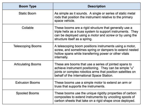
There are several types of booms that have appeared in our research, each with varying degrees of complexity:
There may be other specific types of booms, but these are space industry standards and encompass the vast majority of space booms used since the 1960. This research does not focus on static booms because they are constrained by launch vehicle fairing. The rest of the boom types on the other hand use innovation and technological advances to fit within small spaces, but allow instruments to conduct tests well away from the primary mission vehicle. This leads to a value function for booms: to take up as little space, to use as little mass, and to maintain affordability, allowing the maximization of spacecraft features and instruments.
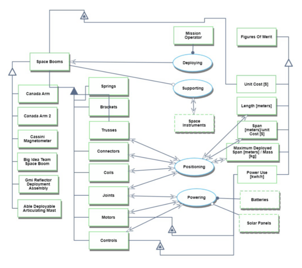
The research into booms is ongoing, but there is already a celebrity list of booms that are both interesting and demonstrate great engineering. CanadaArms 1 and 2, the Magnetometer Boom that crashed with Cassini into Saturn, and the longest rigid span space structure ever, the Able Engineering ADAM Mast that supported the Space Shuttle Topography Mapping in 2000. From our growing list of research subjects, a reasonably complete list of boom parts is available; enabling a consistent decomposition across the various types. The decomposition is listed in the OPM and allows for Level 4 (component) analysis to be accomplished.
Space booms are not the lead actors for the space movie. However, they are critical infrastructure and enable significant improvements in capability. To make gains in the space boom technology arena means taking advantage of component technology and advanced material sciences to reduce cost, mass, and launch volume to span ratio in order to maximize space mission effectiveness.
Design Structure Matrix (DSM) Allocation
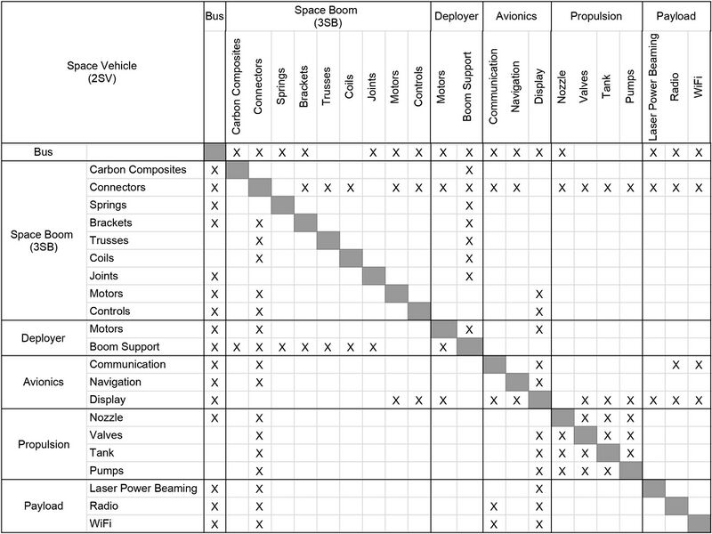
This DSM shows that space booms are part of the larger space vehicle system, where a space vehicle could be a satellite, a rover, or another type of payload. As a L3 technology, space booms rely on other L3 technologies like propulsion, and enable other L3 technologies like payloads. Space booms rely on enabling L4 technology such as carbon composites and controls.
Roadmap Model using OPM
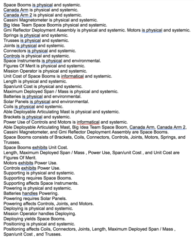
On the left is an Object Process Diagram (OPD), which captures the figures of merit, several examples of space booms, and the main processes and components involved in building and operating a space boom. An Object Process Language (OPL) description of the roadmap scope is auto-generated and shown on the right. It reflects the same content as the previous figure, but in a formal natural language.
Figures of Merit
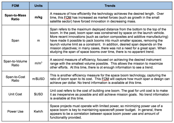
The table below summarizes several figures of merit (FOM) to measure space boom technology. The FOM in bold, span-to-mass ratio, is the primary focus of study.
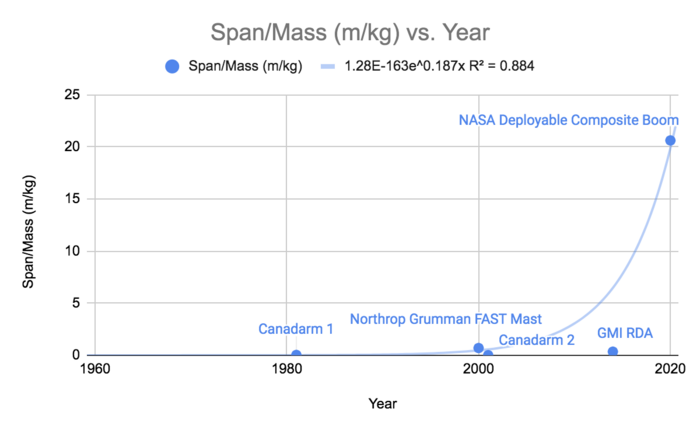
This figure shows the development of the span-to-mass ratio over time. This show a significant improvement in recent years by NASA's Game-Changing Development team, which is working on deployable composite booms (DCB).
Alignment of Strategic Drivers
Based on the displayed FOMs, our team can define our strategies, set targets for success, and then use our roadmap to determine if they are feasible now or require patience before execution. The below chart depicts the strategies we considered, the targets associated based on roadmap FOMs, and whether or not they are currently viable:
Strategic driver number one is an effort to compete in the commercial composite spoolable boom arena. Given the existing material properties, market costs, and recent NASA research into boom geometry, we believe we can outpace current commercial efforts.
