Difference between revisions of "In-Space Additive Manufacturing"
| Line 11: | Line 11: | ||
[[Image:Overview_Image.png|center|1000px]] | [[Image:Overview_Image.png|center|1000px]] | ||
In-space additive manufacturing involves the fabrication, assembly, and integration of components beyond Earth’s atmosphere. Technologies in this area focus on fabricating a product with improved performance or reduced cost compared to existing Earth-fabricated products using manufacturing equipment with a rapid production rate, long life, and low size, weight, and power (SWaP). The additive manufacturing units use the layer-wise deposition of material to build up required component geometries. The energy source for the addition of material can either be mechanical, thermal, electrical, or chemical. For in-space additive manufacturing to prove viable, it must be possible to fabricate a variety of components in the required materials and geometries while meeting requirements on tolerances, surface roughness, and lead time. The reference case in the technology roadmap is the manufacturing of spare parts for a roundtrip Mars mission. | |||
==Design Structure Matrix (DSM) Allocation== | ==Design Structure Matrix (DSM) Allocation== | ||
Revision as of 05:15, 8 October 2019
Technology Roadmap Sections and Deliverables
The clear and unique identifier for this technology roadmap is:
- 2ZGAM - Zero Gravity Additive Manufacturing
This indicates that we are dealing with a “level 2” roadmap at the specific implementation level (see Fig. 8-5), where “level 1” would indicate the over branching roadmap and “level 3” or “level 4” would indicate an individual technology roadmap.
Roadmap Overview
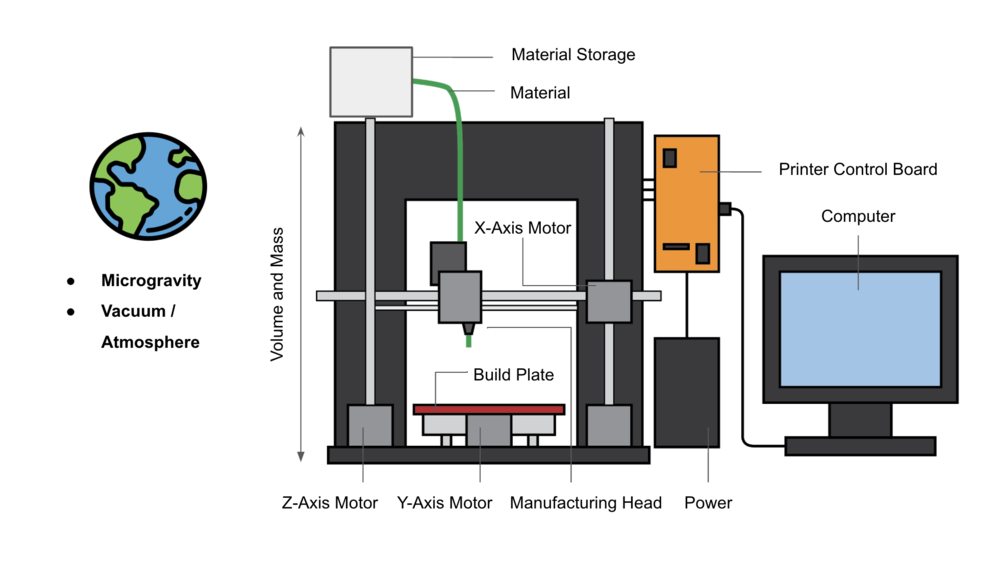
The working principle and architecture of in-space additive manufacturing is depicted in the below.
In-space additive manufacturing involves the fabrication, assembly, and integration of components beyond Earth’s atmosphere. Technologies in this area focus on fabricating a product with improved performance or reduced cost compared to existing Earth-fabricated products using manufacturing equipment with a rapid production rate, long life, and low size, weight, and power (SWaP). The additive manufacturing units use the layer-wise deposition of material to build up required component geometries. The energy source for the addition of material can either be mechanical, thermal, electrical, or chemical. For in-space additive manufacturing to prove viable, it must be possible to fabricate a variety of components in the required materials and geometries while meeting requirements on tolerances, surface roughness, and lead time. The reference case in the technology roadmap is the manufacturing of spare parts for a roundtrip Mars mission.
Design Structure Matrix (DSM) Allocation
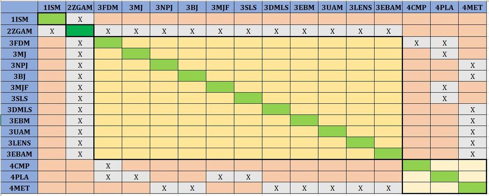
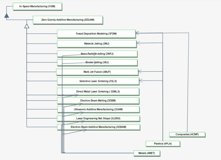
Zero Gravity Additive Manufacturing (2ZGAM) is part of an umbrella of In-Space Manufacturing (1ISM) techniques which includes In-Space Surface Manufacturing as well. Due to the nature of zero gravity mechanics, techniques such as Stereolithography & Digital Light Processing (Vat Polymerization) cannot be used and are not captured in this first-level DSM. 2ZGAM requires the following key enabling technologies at the process level: 3FDM Fused Deposition Modeling, 3MJ Material Jetting, 3NPJ NanoParticle Jetting, 3BJ Binder Jetting, 3MJF Multi Jet Fusion, 3SLS Selective Laser Sintering, 3DMLS Direct Metal Laser Sintering, 3EBM Electron Beam Melting, 3UAM Ultrasonic Additive Manufacturing, 3LENS Laser Engineering Net Shape, and 3EBAM Electron Beam Additive Manufacturing. In turn, these require enabling technologies at level 4, the material component level: 4CMP Composites, 4PLA Plastics, and 4MET Metals.
Roadmap Model using OPM
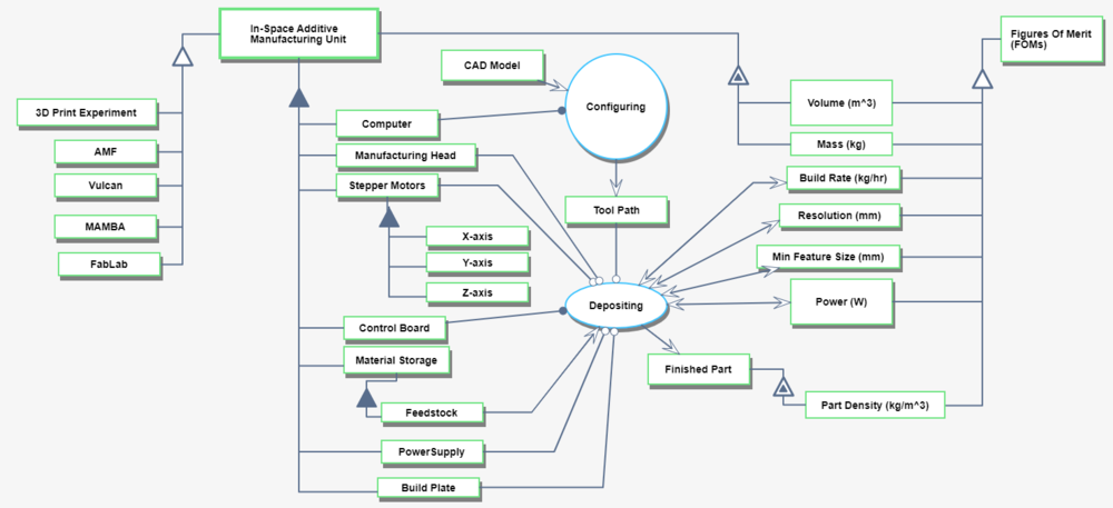
We provide an Object-Process-Diagram (OPD) of the 2ZGAM roadmap in the figure below. This diagram captures the main object of the roadmap (In-Space Additive Manufacturing Unit), its various instances including development projects, its decomposition into subsystems (build plate, manufacturing head, stepper motors …), its characterization by Figures of Merit (FOMs) as well as the main processes (Configuring, Depositing).
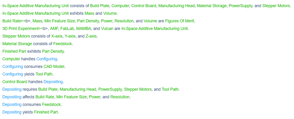
An Object-Process-Language (OPL) description of the roadmap scope is auto-generated and given below. It reflects the same content as the previous figure, but in a formal natural language.
Figures of Merit
The table below show a list of FOMs by which solar electric aircraft can be assessed. The first four (shown in bold) are used to assess the aircraft itself. They are very similar to the FOMs that are used to compare traditional aircraft which are propelled by fossil fuels, the big difference being that 2SEA is essentially emissions free during flight operations. The other rows represent subordinated FOMs which impact the performance and cost of solar electric aircraft but are provided as outputs (primary FOMs) from lower level roadmaps at level 3 or level 4, see the DSM above.
Besides defining what the FOMs are, this section of the roadmap should also contain the FOM trends over time dFOM/dt as well as some of the key governing equations that underpin the technology. These governing equations can be derived from physics (or chemistry, biology ..) or they can be empirically derived from a multivariate regression model. The table below shows an example of a key governing equation governing (solar-) electric aircraft.
Alignment with Company Strategic Drivers
The table below shows an example of potential strategic drivers and alignment of the 2SEA technology roadmap with it.
The list of drivers shows that the company views HAPS as a potential new business and wants to develop it as a commercially viable (for profit) business (1). In order to do so, the technology roadmap performs some analysis - using the governing equations in the previous section - and formulates a set of FOM targets that state that such a UAV needs to achieve an endurance of 500 days (as opposed to the world record 26 days that was demonstrated in 2018) and should be able to carry a payload of 10 kg. The roadmap confirms that it is aligned with this driver. This means that the analysis, technology targets, and R&D projects contained in the roadmap (and hopefully funded by the R&D budget) support the strategic ambition stated by driver 1. The second driver, however, which is to use the HAPS program as a platform for developing an autonomy stack for both UAVs and satellites, is not currently aligned with the roadmap.
Positioning of Company vs. Competition
Technical Model
Financial Model
The figure below contains a sample NPV analysis underlying the 2SEA roadmap. It shows the non-recurring cost (NRC) of the product development project (PDP), which includes the R&D expenditures as negative numbers. A ramp up-period of 4 years is planned with a flat revenue plateau (of 400 million per year) and a total program duration of 24 years.
