Satellite Lasercom
Technology Roadmap Sections
- Technology Roadmap Identified as 3SLC - Satellite Laser Communication
This indicates a Level 3, Individual-Technology Level Roadmap
Roadmap Overview
Satellite Laser Communication (LaserCom) is a method of transferring data through an optical link using an onboard high-power laser system. This breaks from the historically standard Radio Frequency (RF) communication that has been used for satellites uplink and downlink since their inception. While a modern day RF communication link is considered high performing in the 100 - 500 MegaBit per second (Mbps) downlink data rate, an optical link can outperform this by up to 4 orders of magnitude. The TeraByte InfraRed Delivery (TBIRD) from NASA and MIT Lincoln Labs was able to demonstrate a sustained downlink of up to 200 Gbps in 2023. Lasercom data transfer may occur via uplink: ground station to satellite, downlink: satellite to ground, or intersatellite links: satellite to satellite. However, this technology is not without its challenges and limitations. Namely, a direct and accurately pointed path is required from lasercom source to its destination terminal in order to establish a valid link. In high orbital period orbits, such as LEO this may only allow for a link lasting several minutes per period. However, even with this limitation Lasercom technology allows vastly higher communication data rates and total information transfer at 10-100x that of the more conventional radio frequency communications.
How it works: Lasercom utilizes the ability to create oscillations in light waves in lasers to pack a high data volume into the data beam waveform. In its simplest form, information is transmitted by modulating light and broadcasting it over some medium (wire or air). Following this logic, we understand the driving physical limitation is the frequency of the light; how much information can be encoded in modulation in a unit time. The higher the frequency of the light used, the faster the signal can be modulated and the throughput is increased. The defining disruptive aspect of optical communication is exactly this: a fundamental shift along the electromagnetic spectrum from radio waves to higher optical frequencies, yielding much larger data bandwidth possibilities.
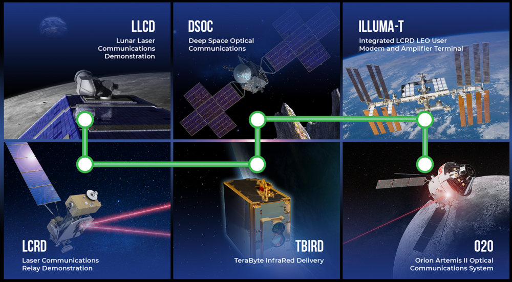
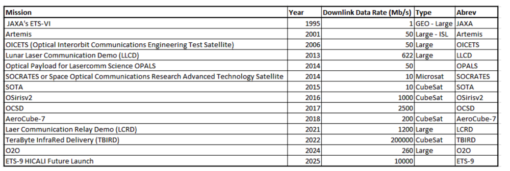
Advancement and proliferation of optical communication in space has enabled new capabilities that were previously not feasible due to data bottlenecking. As seen in the 2EOS roadmap, Earth observing imaging platforms are increasing in both spatial and spectral resolution. A key example is the Hyperspectral Imager Suite (HUSI) hosted on the ISS, which currently generates 300 GB of data per day. At this rate, the ISS cannot wirelessly downlink the imagery and data is currently transferred through hard drives on cargo ships! Current technology is also moving towards proliferated sensors rather than a few larger imagers, all greatly increasing the amount of raw data that needs to be transmitted to ground stations for processing and analysis. With all these trends, conventional RF communications can only be pushed so far and the need for lasercom terminals becomes apparent and necessary. Some RF transceivers have achieved appreciable data rates, such as the Integrated Solar Array and Reflectarray Antenna (ISARA) in 2017 at 100 Mbps, and some transmit only payloads can exceed that (Syrlinks EXC27 in 2015 at 140 Mbps), but they reach a practical limit in terms of SWaP when hosted on small sats. Optical payloads have steadily increased in proven data rates, from the JAXA ETS-VI at in 1995 1 Mbps, to Lunar Laser Communication Demo in 2010 at 622 Mbps, and more recently the Laser Relay Communication Demo in 2019 at 1.2 Gbps. This progress has recently culminated in the groundbreaking 200 Gbps link achieved by the NASA/MIT LL TeraByte InfraRed Delivery (TBIRD) lasercom terminal during a May 2022 flight test.
NASA's Official Laser Communication Relay Roadmap
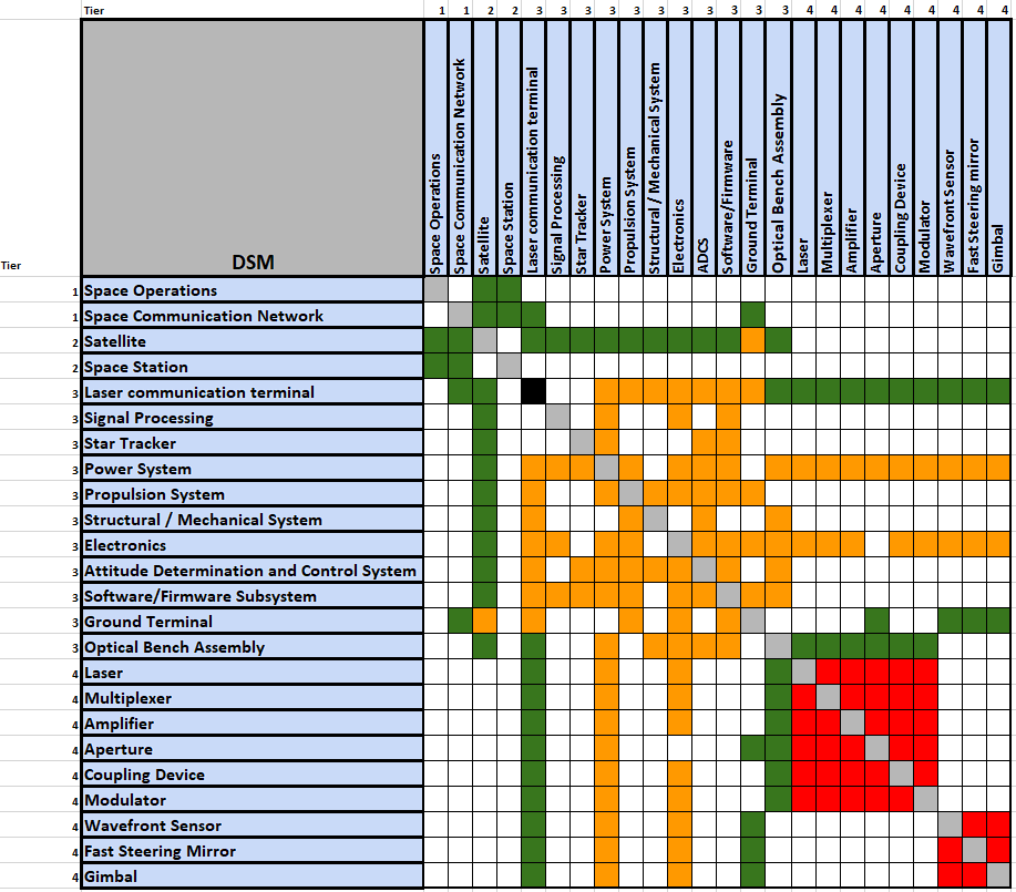
Design Structure Matrix (DSM) Allocation
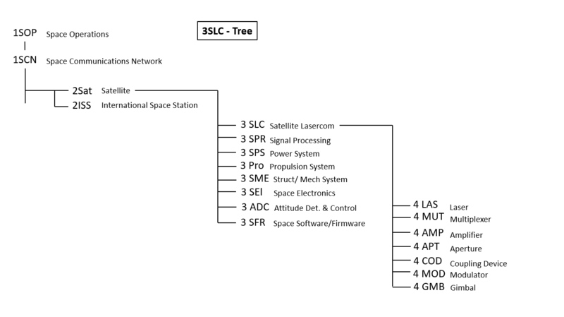
The 3SLC-Tree that can be extracted from the DSM shows that Satellite Lasercom (3SLC) is a Individual Level Technology that is a part of a larger Satellite (2SAT) Technology that lives within the highest level Technology classifications of Space Operations (1SOP) and Space Communications Network (1SCN). Many other satellite Subsystems exist at level 3 alongside Satellite Lasercom (3SLC) and comprise the satellite. Furthermore, many individual technologies serve enabling technologies to Lasercom at Level 4. This tree is highlighting those specific technologies for LaserCom and not all of the level 4 technologies that are necessary for other satellite subsystems.
Roadmap Model using OPM
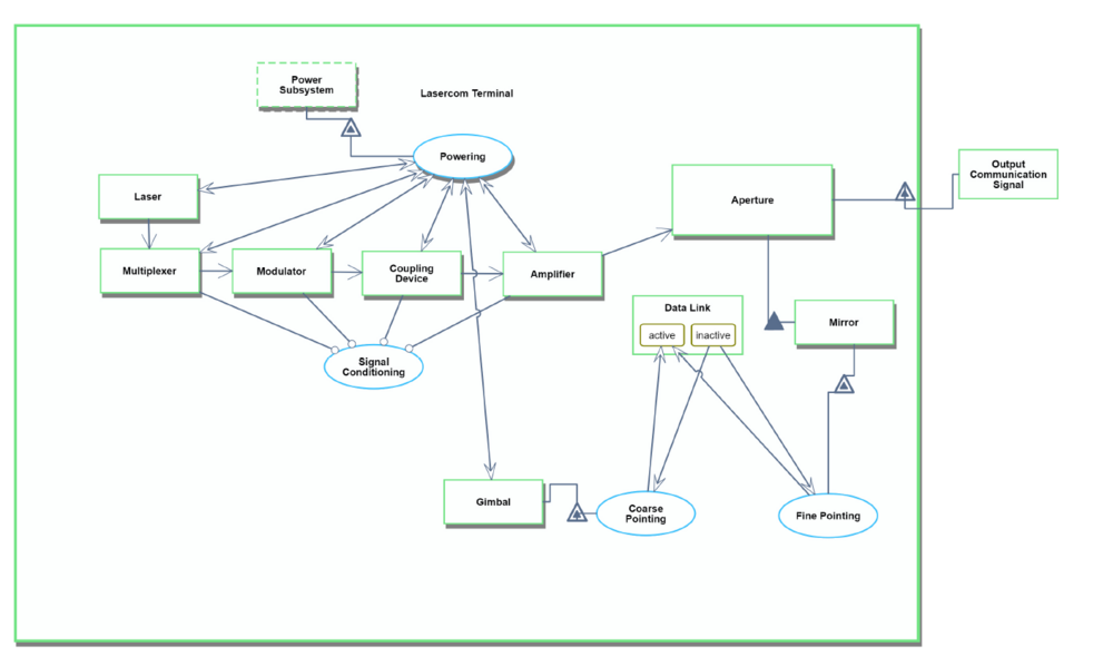
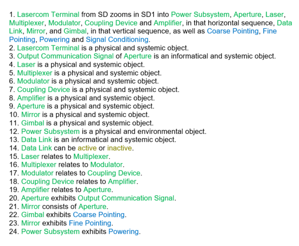
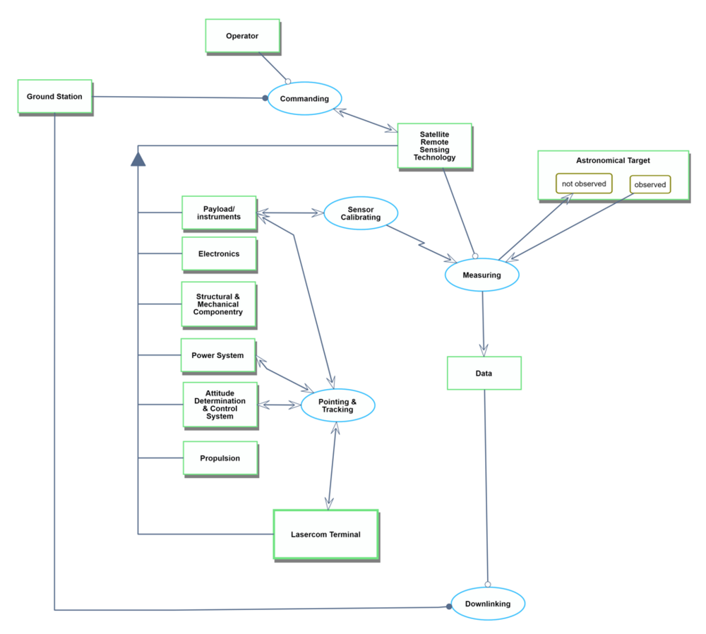
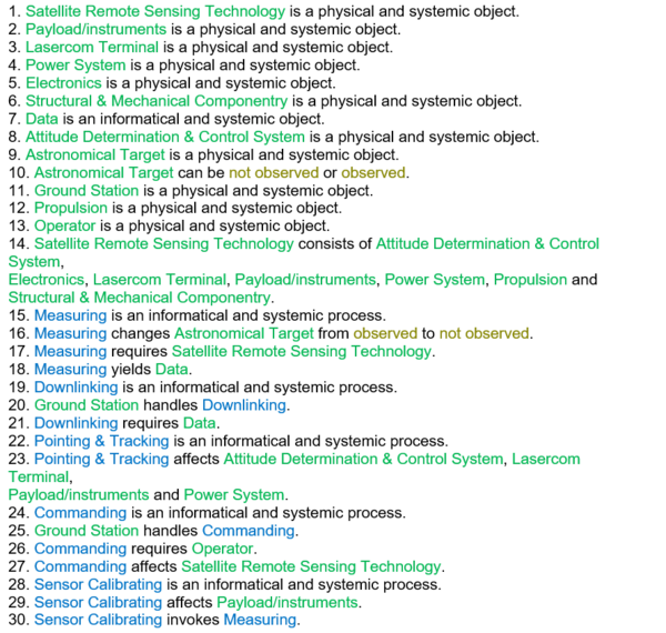
Object-Process-Diagrams (OPD) of the 3SLC roadmap is provided in the figure below. The first diagram captures the main object of the roadmap (Lasercom Terminal) and it's enabling technologies and operational interactions. A higher level OPD is also included here to explain how the Lasercom Terminal fits and interacts at the Satellite Level (Satellite Remote Sensing Technology).
Figures of Merit
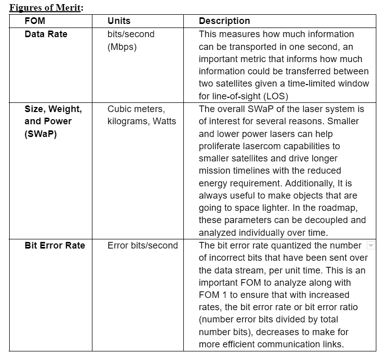
The driving Figure of Merit for lasercom is data rate, particularly the satellite downlink data rate in which the satellite sends information it has collected to the ground station on Earth. A key motivator for pursuing the development of Lasercom technology is to create higher throughput data links in space, beyond what has been available through traditional radio frequency communications. Lasercom allows for a drastic multiplication of downlink data rates, for example a satellite operating at a ~100 mbps downlink is on order for a high performance RF DL link on a large satellite in the X-band and there are plans to attempt a 2 Gbps X-band link, while NASA and MIT Lincoln Labs TBIRD 6U CubeSat has used lasercom to demonstrate a 200 Gbps downlink. Albeit the comm window is much smaller as the satellite has much more precise pointing requirements and atmospheric conditions than RF comm payloads. Even amongst this more stringent communication window lasercom allows a program to collect 10x - 100x more data that of RF based satellite systems: https://www.nasa.gov/communicating-with-missions/lasercomms/ This multi-order throughput result drives the case of lasercom in the data rate figure of merit. It proves lasercom systems to be highly desirable satellite capability as it has opened up what has historically been a bottleneck of satellite information transfer through restricted communication capabilities.
To ensure the viability of lasercom for use on small satellites, the overall Size, Weight, and Power (SWaP) of the terminal are important FOM. System weight has been trending down over the years from advances in shrinking powerful lasers. Roughly 10 years ago, terminals were upwards of 6 kg with the NICT SOCRATES device yet nowadays payloads are reaching sub-kilogram specifications (DLR OSIRIS4). On the other hand, power consumption values have been consistent over the past decade, varying from <5 W (NICT VSOTA) to 100 W (TBIRD). Power can vary depending on the underlying laser technology and transmitting scheme and is closely related to other FOM for the link budget that can extend beyond the transmitting lasercom terminal. These link budget parameters include beam width, pointing accuracy, receiving telescope diameter, receiving terminal sensitivity, and bit error rate. Utilizing a simple link budget equation that folds in all the ground terminal and lasercom system parameters, along with atmospheric attenuation factors, one can model communication performance. This output can be used to perform sensitivity analyses, understand which link geometries are possible with different technologies, and identify which aspects to improve through investments and R&D.
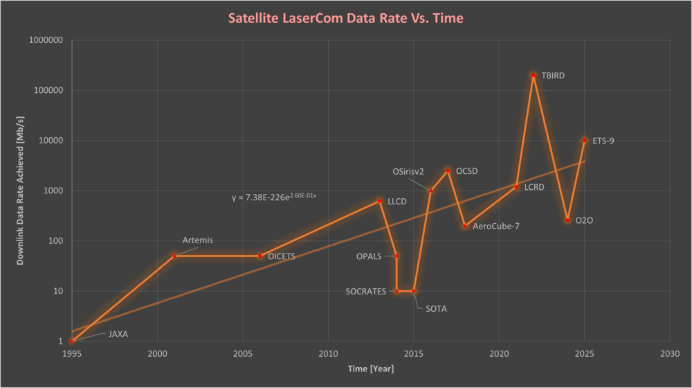
There has also been a significant increase in the capabilities of lasercom itself over the past 28 years, particularly in the achieved downlink data rate field. This progress has been captured (made by the date collected by the team) in the plot below, from various space missions since the first demonstration in 1995 from the JAXA program at 1 Mpbs to the 2022 demo of TBIRD at 200 Gpbs. Note the plot needs to be scaled logarithmically on the y-axis in order to distinguish the scale of progression in a readable format.
Modeling Rate of Improvement: While this timeline does a good job of creating an overall picture of the progress made in Lasercom both in rapidly improving optical data rate, dL, capabilities and increasing frequency of lasercom mission/investment of all satellite types, it is a bit tricky to model a representative δdL/δt due to the range of missions (demos, functional terminals, ect), satellite platforms, orbits and orbit/orbital altitude. Furthermore, the recent TBIRD demo is a serious outlier, it’s a promising sign for the future of lasercom and achievable dL, but it skews any form of least-squares regression fit to the model. However, an overall trendline and equation can be formatted pretty nicely to the logarithmic y-axis as shown below.
This trendline is modeled off of the exponential equation:
Since this is an exponential equation mapped to a logarithmic plot, it actually tracks well linearly and can be used to get a reasonable estimate of achieved average lasercom data rate at any given year. For example in 2016 it estimates a dL of 322 Mbps. Extrapolating this out to say 2030, yields an estimated average data rate of 1.23 Gbps. This is likely a reasonable estimate considering the TBIRD demo tech follow ups are looking to place many TBIRD-based terminals on future missions in the coming years.
Lastly, the derivative of Eq. 1 can be taken to get the instantaneous δdL/δt of this trendline. Calculating this derivative (which is actually super easily for e^x, just apply chain rule) yields:
This equation can be used to calculate the instantaneous rate of change for downlink data rate via lasercom at any given year. For example at year = 2022, δdL/δt is 398.4 Mbps, but as this technology continues to progress into the future at year = 2025, this model predicts δdL/δt to be 869.1 Mbps.
Alignment with Company Strategic Drivers
Positioning of Company vs. Competition
Technical Model
Financial Model
List of Demonstrator Projects
Key Publications, Presentations and Patents
Technology Strategy Statement
References
[1]Williams, D., “RF and optical communications: A comparison of high data rate ... - core,” NASA Available: https://core.ac.uk/download/pdf/10536487.pdf.
[2]Schauer, K., “NASA Laser Communications Innovations: A timeline,” NASA Available: https://www.nasa.gov/missions/tech-demonstration/nasa-laser-communications-innovations-a-timeline/.
[3]“Laser Communications Relay Demonstration (LCRD) overview,” NASA Available: https://www.nasa.gov/directorates/stmd/tech-demo-missions-program/laser-communications-relay-demonstration-lcrd-overview/.
[4]“The nobel prize in physics 2023,” NobelPrize.org Available: https://www.nobelprize.org/prizes/physics/2023/press-release/.
[5]“9.0 communications,” NASA State of the Art Report Available: https://www.nasa.gov/smallsat-institute/sst-soa/soa-communications/.
[6]On-orbit demonstration of 200-Gbps laser communication downlink from ... Available: https://ntrs.nasa.gov/api/citations/20230000434/downloads/Schieler%20paper%20spie2023-tbird-v4.pdf.
[7]“Laser Communication in space,” Wikipedia Available: https://en.wikipedia.org/wiki/Laser_communication_in_space.
