In Space Propellant Depot
Roadmap Overview
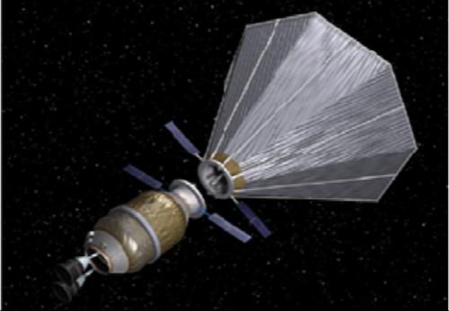
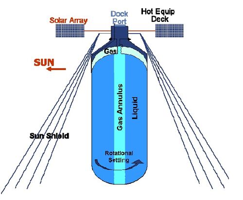 <ref> Kutter,B.F., et al. (2011, September, 9-11) A Practical, Affordable Cryogenic Propellant Depot Based on ULA’s Flight Experience</ref>
In the late 1800s James Dewar became famous for his study in the liquefaction of gases such as hydrogen and oxygen. Current Cryogenic storage containers are referred to as dewars. In the 1959 both LOX and LH2 were used to propel the second and third stages of the Saturn rocket. In 1966 LH2 and LOX were chosen to power the Atlas-Centaur rocket. “As early as 1928, scientists studying interplanetary travel began arguing that pre-positioning propellants in orbit would be required for any sustainable large-scale travel beyond Earth.” <ref>Goff Ja et al. “Realistic Near-Term Propellant Depots: Implementation of a Critical Spacefaring Capability” p 2 </ref>. In 2007 Boeing addressed the value of creating propellant depots to increase the payload one could carry to future moon missions <ref> Benioff, D. (2007, October, 1-5) LEO Propellant depot: A commercial opportunity </ref>. This idea was also brought up to Masten space systems in 2008 <ref>Goff, J. et al.(2008) The Case for Orbital Propellant Depots </ref> In 2010 ULA (United Launch Alliance), began to develop ACES (Advanced Cryogenic Evolved Stage) which was a high-performance upper stage rocket with the ability to store and transfer propellant to later missions. ULA also was working on creating CRYOTE (Cryogenic Orbital Testbed) to demonstrate the feasibility of cryogenic fluid management in micro and zero gravity <ref> Gravlee, M., et al. (2011) Cryogenic Orbital Testbed (CRYOTE) Development Status </ref>. In 2018 Vice President Pence at the 34th Space Symposium outlined the plan to have NASA return to the moon with the eventual use of a space depot. <ref> Pence, M.R. (2018, April, 16) Remarks by Vice President Pence at the 34th Space Symposium | Colorado Springs, CO </ref>. To date though there has been no space tested propellant depot.
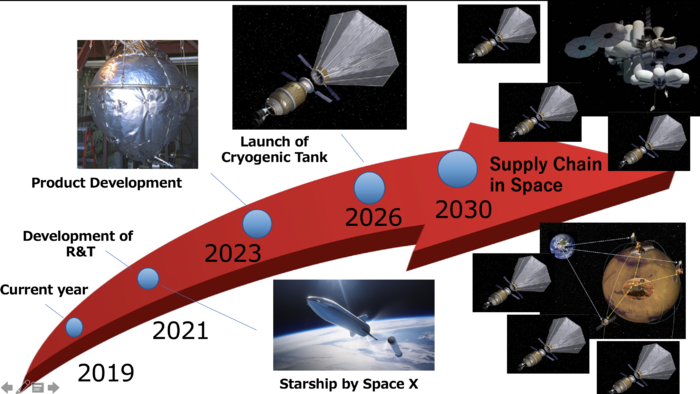
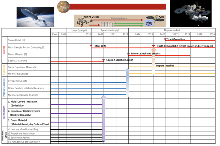
In the next decades, huge events will be excited in the space, such as "Space Hotel" and "Mars Exploration". These events clearly show new era of the space and they will increase the needs of new supply chain to sustain these events. Every car needs gas station to go to fur place, our development, "In Space Propellant Depot" will be the significant supply chain in the space. To succeed our goal, we start our development and R&T from 2020 to 2021, produce product from 2022 to 2025 and then launch them in 2026. Other development such as Starship, which make possible to launch a heavy payload with cheap cost will be necessary to achieve our goal.
Object Process Diagram
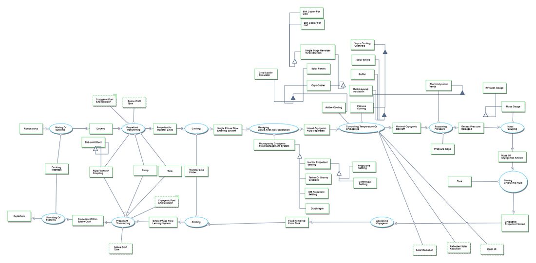
The above diagram shows the objects and processes required for an in-space propellant depot to function. This OPD includes both elements which are required, like a tank which handles storing the Cryogenic Fluid and some elements which are optional such as the cryocoolers to actively cool the cyrogenic fluid. But overall, the processes and operands in this diagram should allow for a good understanding of what is done by an orbital propellant depot. Since this technology has never actually been demonstrated in its intended environment, it is important to include this OPD to allow understanding of the technology.
In-Space Propellant Depot Roadmap OPM
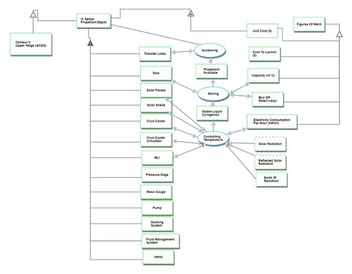
In the previous OPD there are a lot of processes and operands, which can make it difficult to quickly understand what the important aspects of the OPD are. This OPD details the technologies needed for an orbital propellant depot, their functions and how they relate to our FOMs. This simplified OPD is more digestible and integrates with the project management side of developing this system.
Most of the technologies in the OPD are relatively high TRL.
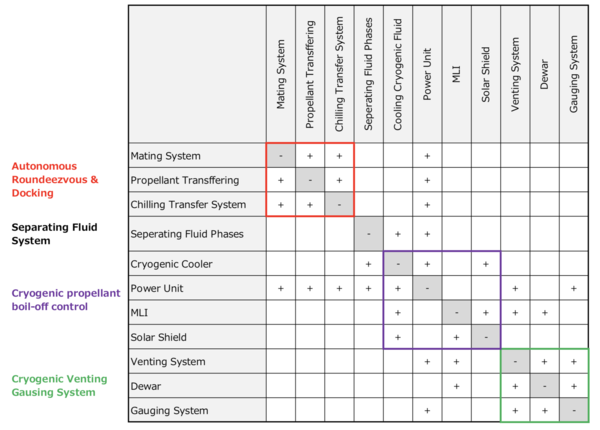
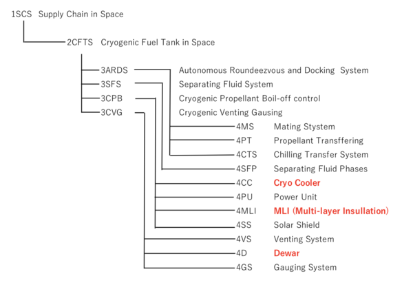
Design Structure Matrix & Technology Trees
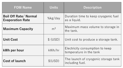
Figures of Merit
The FOMs are following:
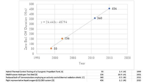
Figure of Merit Trends
The above graph shows data for the developed testbeds which did in fact reach Zero Boil-Off (Duration vs. Year). Albeit these are for different gases, the first two are LH2 and the second two are LN2 (simulating LOX). LH2 has to be stored below 20K and LOX needs to be stored below 90K. The methodology used for storage is the same (aside from the necessary temperature), so the progress in duration of sustained zero-boil-off is still relevant since the improvements for one could be used for the other. The dFOM/dt found is 24.4 hours ZBO/year.
For this specific FOM the theoretical limit is likely close to inifite, but once long term ZBO is attained there would be other figures of merit which would have limits. For example, the power necessary to sustain ZBO would have a limit based on the amount of power which could be generated by the solar panels and the structure to support them. Similarly, the capacity of the tanks would have limits based on the structural limitations and the force of gravity of the depot.
Were the testing on each of these done for longer duration there would be significant boil-off <ref> Chai,P.R., et al. (2013, December, 16) Cryogenic thermal system analysis for orbital propellant depot</ref>. A better predictive metric would be the % boil-off per month, but none of these tests were performed for a month or more. The current state of the FOM is slowly increasing but is limited by the cooling capacity of the cryocoolers currently available. Were the Fuel used to be liquid methane instead of LH2, the completion of the development of a 150W 90K cryocooler by Creare (being funded by NASA) <ref> Platcha, D. (2017, July, 7) NASA cryocooler technology developments and goals to achieve zero boil-off and to liquefy cryogenic propellants for space exploration </ref> would allow ZBO for a propellant depot containing LOX [7]. Methane has a higher boiling point, so it would likely be able to sustain ZBO as well. Both SpaceX and Blue Origin plan on using Methane/LOX powered rockets, so this may well be a useful and attainable technology in the near future.
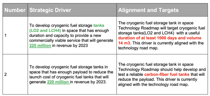
Alignment with "Company" Strategic Drivers: FOM Targets
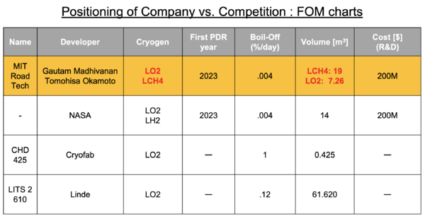
Positioning of Company vs. Competition : FOM charts
In order to better understand the current state of cryogenic storage a comparison was made between our theoretical system and some other systems. It seems fair to compare our system to at least one other theoretical space based system. For this we used the NASA system described in the road map. To determine the boil off, we used the first paper discussed in question 2 which calculated the boil off for a theoretical system using modern day cryocoolers. Since NASA would be using LH2 as a cryogen, and the cooling capacity wouldn’t have increased much from what was described in the paper (10W to 20W; 120W needed for ZBO), I believe that this is a fair estimate. The other two systems which were chosen were different sized LO2 storage tanks which are earth based. While the architecture of both is different the working principle is the same. Only the theoretical cost for the NASA system was readily available, in order to acquire the cost for the other two a quote would need to be requested.
Technical Model: Morphological Matrix and Tradespace
One of the most important FOM for this system is the duration which it can sustain a cryogen. This is determined by how long the system can keep the boil off rate at zero. Patel, C. N. et al “Design of Low Heat Leak Liquid Helium Dewar” 2016 showed a simple method to model the performance of a dewar (cryogen storage container) along with actual values corresponding to the variables, which was challenging to find for commercially developed cryogenic storage tanks. Even though this paper is creating a helium dewar, the relationship between the variables is relevant for different cryogens. Since the cryogenic tank was insulated using MLI (multi layered insulation) the equation developed by lockheed martin to model the performance of MLI was used to model the heat flux through the body of the tank. There are multiple models for MLI heat flux, this one was chosen since due to its frequency of use in the field. Multiplying this by the inner surface area of the tank gives the heat transfer through the MLI of the dewar

q W/m Heat Flux through the MLI
Cs(Cc) 8.95E-08 Solid Conduction Coefficient
Cr 5.39E-10 Radiation Coefficient
Th 300 K Temperature Hot
Tc 4.5 K Temperature Hot
Tm 152.25 K Temperature Average
N 20 layers/cm
NS(n) 40 #Layers of MLI
ε0 0.02 Emissivity
A 40 m^2 Internal Surface Area
he 214000 J/kg Heat of Evaporation
D 3 m Diameter
L 3 m Length
V 25 m^3 Volume
ρ 1141 kg/m^3 Density
mtotal 30*10^3 kg Total Mass
The cooling capacity of a cryo-cooler can be incorporated using the equation. Subtracting the cooling capacity from the heat transfer through the MLI can be used to approximate the total heat transfer through the system.

Qcryo 8W Cooling Capacity
η 9% carnot efficiency
Pin 213W power input
Tload 90K load temperature
Treject 300K rejection temperature
The boil off rate can be determined by multiplying the heat transfer by the conversion factor of 86400 (60s/min*60min/hr*24hrday) then dividing by the latent heat of vaporization and the total mass. The resulting equation is

The variables which could be varied by design without changing the cryogen, are the area (A), MLI density (N), emissivity (ε0), Carnot Efficiency(η), Power input (Pin),and number of radiation shields (Ns).
![]()
![]()
![]()
![]()


Once the values were entered and the derivatives were normalized the values were plotted in the tornado chart below. From this it can be seen that increasing the density of the MLI (layers/cm) has the strongest effect per percentage on increasing the boil off rate. Also while Volume (another one of our figures of merit) is not specifically defined in this equation, the area (A) is. It can be seen that increasing the area increases the BOR. Since the area is directly related to the volume (where area is dV/dr) it can be seen that the FOM of volume is in tension with the FOM of BOR. Increasing amount of layers of MLI decreases the boil off rate. From this analysis the two variables related to the cryocooler don't seem to have a significant effect on the boil off rate.
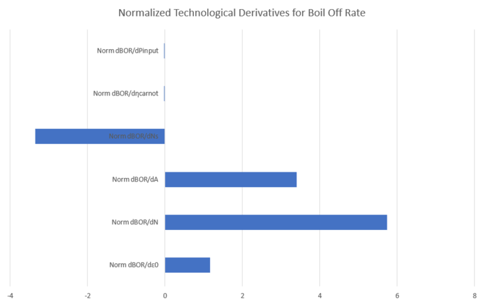
Based on this analysis, to get a low boil off rate I would want a dewar with many layers of MLI, which are spaced very far apart with very low inner surface area. The problem with this approach is that the mass and the volume of the tank will quickly increase due to the added layers and the space between them. On a given space craft which would launch this tank, there would be limited space. It would be more profitable if this space could be dedicated to propellant as opposed to MLI. Also long periods in space deteriorate MLI due to the harsh space environment(radiation, solar wind, thermal cycling, micro-meteriods, and atomic oxygen <ref>Mohammed, J,S. et al, (2011), "Degredation of Multi-Layer Insulation(MLI) retrieved from the Hubble Space Telescope</ref>). This would decrease the effectiveness of the MLI and could result in the creation of heat shorts which is where the energy would bypass the MLI section of the thermal circuit. Heat removal using a cryocooler is the only method available to combat heat shorts. So while optimizing the MLI used for the tank is valuable, increasing capability of the active cooling is a more profitable method for decreasing the BOR.
Per guidelines defined by <ref>Behrens, G. et al (1997 March) " Guidelines for the Design of Cryogenic Systems"</ref>, cylindrical dewars (cryogenic storage vessels) must be able to withstand 1 atm. The thickness of the walls of this dewar can be calculated using the equation
![]()
where Pa is the ambient pressure of 15 psi (simplified to P in our equations
k is a correction factor based on the tank dimensions (49 for our dimensions)
E is the modulus of elasticity for the tank (2.77E7 psi for steel)
D is dewar outer diamter (104 inches used)
t is the wall thickness and (.37 inches used)
n is the factor of safety (value of 4 is used)
With this information the volume of the dewar can be calculated

From the equation for volume the partial derivatives of the variables can be calculated along with the sensitivities
![]()
![]()
![]()
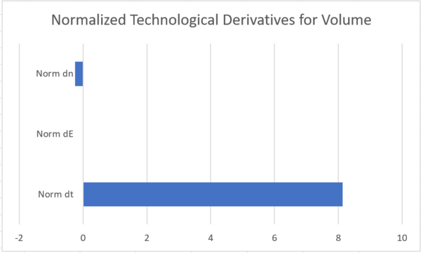
From the graph it can be seen that the wall thickness has the strongest effect on volume. It should be mentioned though that while increasing the thickness would increase the allowable volume of the tank, it would also increase the weight of the tank. This increase in weight would cause tension with another one of our FOMs , the cost to launch into space, so the trade offs would have to be analyzed. Changing the factor of safety doesn't have as strong of an effect, but increasing the factor of safety (while holding the other variable stable)would require a decrease the volume. This graph does make it seem that Young's modulus has as strong an effect as the other variables, but changing the material could change Young's modulus by an order of magnitude, which may have a significant effect.
Both sensitivity analyses show the value of maximizing the radiation shields and tank thickness. Both of these variables are limited by certain constraints or are in tension with other aspects of FOMs. So while our project will attempt to maximize these, since they are not scalable our project will invest R&D into the variables that have more scalability, even though our FOMs are not as sensitive to them. The power input and efficiency of the cryocooler is scalable, so this is a technology which we would invest into. Since the volume isn't very sensitive to young's modulus we can research materials that may have a lower value. If this material is also less dense, it would allow for a lower launch cost, another one of our FOMs, for the same maximized thickness.
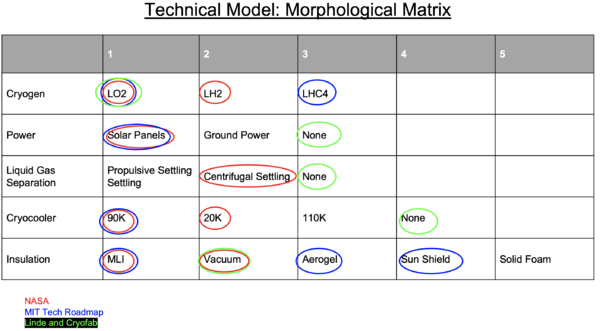
Based on data available from NASA and from suppliers of earth based cryogen storage we were able to create a morphological matrix detailing some of the subsystems used on cryogenic storage devices. Based on the cryogen which is being stored, different equipment may be necessary. For example if a cryocooler was being used, LH2 would need one which operates at a colder temperature.
Anytime that a cryocooler is used, power would be necessary. For both of the earth based systems which were found, cryocoolers were not used, so power was not needed.
For systems in space, predicting the location of the liquid vs the gas can be complicated, to simplify this certain settling methods are used, while on earth based systems this isn’t necessary since the denser liquid settles to the bottom of the tank via gravity.
Insulation is one of the more divisive topics within the matrix since each of the items can be further deconstructed. It does seem that earth based systems typically don’t use MLI or sun shield, while space based generally do.
Keys Publications and Patents
Cryogenic thermal system analysis for orbital propellant depot<ref>Chai P. R. et al (16 December 2013) “Cryogenic thermal system analysis for orbital propellant depot” </ref>
The importance of this paper mainly lies in figure 14 and 15 on page 44 and table 5 on page 45. These figures show for LOX and LH2 the amount of boil off for different designs for different total mission durations. From these, the benefits of active cooling can be seen for storing cryogens. It also shows that there would be a significant benefit to achieving zero-boil off for the cryogen. Table 5 shows what the current cooling capacity is for state of the art cryocoolers, and what would be necessary to achieve zero boil off. While the cooling capacity in order to achieve zero boil off for oxygen is not too far from what the current state of the art is capable of (at the time of this paper), the cooling capacity for hydrogen ZBO is more than an order of magnitude greater than what we are currently capable of.
NASA cryocooler technology developments and goals to achieve zero boiloff and to liquefy cryogenic propellants for space exploration<ref>Platcha, D. et al “NASA cryocooler technology developments and goals to achieve zero boiloff and to liquefy cryogenic propellants for space exploration” 7 July 2017</ref>
This paper is one of the most recent papers available on the topic of in-space cryogenic storage depots. It covers the current status of cryocoolers and details the plans by NASA to develop two new cryocoolers. One of the cryocoolers is intended to move us closer to being able to store hydrogen with ZBO, while the other is for storing LOX. The cooler for LOX, per the previously mentioned paper would have the necessary cooling capacity to store LOX with zero boil-off. This paper also covers the different circulators available for circulating the cryocooler fluid over a large area to cool the entire cryogen tank.
Tank container for transport and storage of cryogenic liquefied gases<ref>Zrim, M. 2012 "Tank container for transport and storage of cryogenic liquefied gases" US Patent 9488313 B2</ref>
This patent posits the use of aerogel, as opposed to vacuum to insulate the contents of a cryogenic storage tank. There are several good reasons for taking this approach. A vacuum needs to be maintained to have consistent insulation. Also vacuum requires both an inner and an outer shell. For space based applications a small door is created on the outer shell of the dewar. When the dewar is no longer in the atmosphere the door is opened to expose the dewar to a vacuum. Two separate shells add weight to the system. Also the manufacture of vacuum storage can be difficult. The aerogel based insulation does not require repeated vacuuming. It can save up to 10kg in a 40 foot cryogen storage container and is not as difficult to manufacture. There is also the added benefit that the aerogel can contain fire preventive material. The benefits of Aerogel options are compared to MLI in Fesmire J.E. “Aerogel-Based Insulation Materials for Cryogenic Applications” 2018. The most valuable FOM for this subsystem is the thermal conductivity, which we are trying to minimize. Per the aforementioned paper, a combination of MLI and Aerogel is one of the more attractive options. This possible reduction in weight without significant increase in thermal conductivity may allow a comparably larger volume cryogenic storage tank.
Container for liquefied gas <ref>Zimmerman, F. 1955 "Container for liquefied gas" US2776069A</ref> This patent is from 1955, but is still relevant to dewar design. The patent details a novel method to apply silver to the inner walls of the dewar. This application of silver helps prevent radiation of energetic particles from entering the vacuum section of the dewar. This helps create a more stable emissivity for the dewar itself. This would be particularly useful for our purposes since over time if particles are able to enter the vacuum section radiation would no longer be the only mode for heat transfer between the space environment and the liquid propellant stored in the dewar.
Method for joining carbon-carbon fiber composite material to metallic material <ref>Masahiko, T, 1994 "Method for joining carbon-carbon fiber composite material to metallic material" JPH07237981A</ref> This patent details a novel approach to mettalize carbon fiber composite. Per the previous patent there is value to applying certain soft metals like gold or silver to the inside walls of the dewar. The previous patents method only covered metals such as stainless steel copper or plastics which were covered in a conductive film. The technique in this patent allows metals to be applied to the inside of the carbon fiber tank. Were a carbon fiber tank to be used as a dewar, this approach would allow metals to be applied to reduce the introduction of radiant heat transfer into a vacuum section which would allow other heat transfer modes.
Cryogenic propellant depot and integral sunshield <ref> Kutter,B. F. et al 2009 "Cryogenic propellant depot and integral sunshield" US8196868B2</ref> This patent details some important technologies relevant to an orbital propellant depot. Specifically, the use of a sun shield to reduce the direct exposure of the propellant tanks to the sun, which would result in reduced radiant heat transfer. Also the use of centrifugal settling of the tanks to ensure separation of the liquid and gas phases inside the tanks. This would ensure that when the propellant is accessed it is single phase flow. Both of these technologies would directly benefit our technology.
Realistic Near-Term Propellant Depots: Implementation of a Critical Spacefaring Capability<ref>Goff, Jonathan & Kutter, Bernard & Zegler, Frank & Marchetta, Jeffrey.(2009). Realistic Near-Term Propellant Depots: Implementation of a Critical Spacefaring Capability. 10.2514/6.2009-6756.</ref>
This paper details some of the options available for various critical subcomponents and the pros and cons of each. For example one of the important subsystems is that of the propellant settling, which keeps the separation between the liquid and gas phases to prevent multiphase flow into the docked spacecraft. The article shows what the current options are and even gives the TRL level for a few. It also details some of the different ways these subsystems have been integrated into theoretical and experimental systems. This article provides specific value for developing a morphological matrix for this technology.
List of R&T Projects and Prototypes
The R&T projects which were researched were ones which directly affected variables identified as contributing to our figures of merit. Specifically, for the FOM of Boil-off Rate R&T projects were selected which could lower the emittance of each layer of MLI, and which had a high input power to the cryocooler which would allow heat which made it past the MLI to be removed. For the FOM of Volume (and Launch cost) we looked into cryogenic tanks which could be made from less dense materials.
Multi Layered Insulation
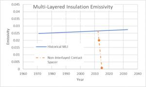
Multi Layered Insulation is the primary method to prevent radiative heat from entering into the cryogenic storage tank. The emissivity level is the amount of energy which is given off by an energized material. For our system, energy is radiated from the sun (and reflected from the earth). When it contacts our system, we would like to minimize the energy which makes it through to the cryogenic tank. Traditionally Dacron, or some other fiber netting is placed as a spacer between the layers of film to reduce conductive heat between the layers.<ref>Miyakita,T. et al, (2015 July 16)"Evaluation of Thermal Insulation Performance of a New
Multi-Layer Insulation with Non-Interlayer-Contact Spacer" </ref>showed that by changing to a new form of spacer a much lower emittance can be attained. The new form of spacer, rather than a netting, are hard interlocking spacers that only contact the film in a very small surface area. This project was compared to other historic data on emittance values for MLI. With the interlocking spacers there is a sharp drop in the level of emittance from the historic data projected forward. This lower emittance level would decrease the rate at which the cryogen would boil-off. There likely will be a hard lower limit to the emittance, but that has not yet been determined by our research.
Cryocooler
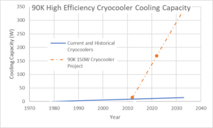
The NASA funded project to create a 150W cryocooler capable of 90 kelvin cooling is very important for the implementation of an orbital propellant depot, since it will allow any of the heat which makes it through the MLI to be removed. This is supported by the paper Chai,P.R., et al. (2013, December, 16) Cryogenic thermal system analysis for orbital propellant depot, which showed that in order to attain zero LOX boil off for 3 years using a realistic numbers of layers of MLI, a 90K cryocooler over 100W would be needed. Previous cryocoolers had a significantly lower cooling capacity (caused by lower efficiency and input power)according to historic data on 90K cryocoolers. There have been multiple recent attempts to increase the cooling capacity of 90K cryocoolers by increasing the input power by the company Creare, which was funded by NASA. This data was compared to the trajectory of the historic data to determine what continual funding in this direction could achieve in terms of cooling capacity. From the graph it can be seen that with the project, there is a sharp increase in slope. This would be highly desirable for our system as it would reduce the boil-off rate of the cryogens.
Density of Tank Material
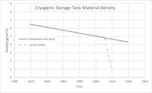
Storage tanks for cryogens are large pressure vessels which are extremely well insulated against incoming heat (sometimes referred to as Dewars). On earth, volume is less constrained and the main limiting factor is the allowable pressure for a specific pressure vessel design. For objects being sent to space, one of the most critical constraints is the weight. For that reason, even though many cryogenic storage tanks on earth are made out of stainless steel, storage tanks used on space vehicles have traditionally been made out of aluminum due to the lower density. There has not been much change in this technology since the introduction of aluminum but historical data is available on when these were introduced. Recent development by NASA and <ref>Md.,S.I. et al (2015 Oct 9) "Investigation of woven composites as potential cryogenic tank materials"</ref>, has shown that carbon fiber can be an effective storage tank for cryogens. So for the same weight of a tank made out of stainless steel, the volume of a tank made of Aluminum would be larger, and the volume of a tank made of carbon fiber would be even larger. Our graph shows the possible decrease in the tank material density if this project is taken up and research is continued in this direction. Sadly since there are not very many data differing data points, it is hard to know with certainty how much the density could decrease over time, but investing in this technology would allow us to move in right direction for one of our figures of merit.
Boil-off%/day
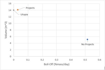
When looking at the two FOMs of Boil-Off%/day and Volume, a clear difference can be seen. The boil-off rate is significantly higher without the cryocooler project and the new MLI. For the same given mass the volume of a tank using a carbon fiber has significantly larger volume than one using aluminum.
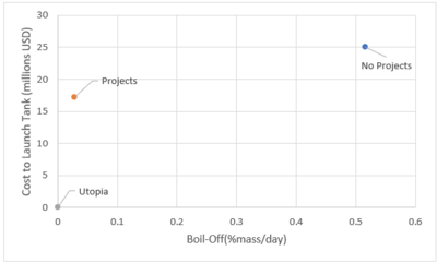
While there hasn’t been a mass limit which was set specifically, the value of having a lighter tank which is able to meet the same volume requirement shows its value when looking at another one of our FOMs,Launch Cost. When using $10000/lb, and the mass of two tanks (both of the same internal volume), the cost to launch the tank can be determined. This is not including the cost any of the other common systems or propellant which wouldn't change depending on the tank material. From this it can be seen that the use of the carbon fiber tank saves close to 8 million dollars, while also having significantly less boil off per day.
Financial Model
In order to make financial model for our project, we assume that our business model, sales, manufacturing cost and R&D expenses are as the following.
Business model:
We hypothesize that our business model is mainly to produce cryogenic fuel storage tank in space, including fuel, and we sell them to customer. In addition, maintenance, which means monitoring of storage tank in space should be included. To simplify our business model, we ignore the launch business and disposal business at this model.
Sales:
According to the reference [1], we have information that customer such as NASA would buy cryogenic fuel for propellant $10,000 per kilogram. Based on this information and volume size of our developing storage tank, it is assumed that each tank of LO2 and LCH4 would be sold in the following price in total $220,000,000.
・LO2: 14.00m3 (16000kg) = $160,000,000
・LCH4: 14.00m3 (6000kg) = $60,000,000
As we draw the roadmap, Moon mission, Exploration of Mars and Space hotel, these big projects will be executed in 2023, 2025, 2026. We believe that each project will highly require both LO2 cryogenic storage tank and LCH4.
R&D expenses:
According to the reference [2], we know that the R&D cost of cryogenic fluid management by NASA is $200 million. Hence, we hypothesize that our R&D cost will be costed approximately $200 million. Our R&D project will be planed from 2020 to 2023, thereby we hypotheses that $50 million per year will be required at least.
Manufacturing cost:
Based on the information of reference [3], in order to produce our storage tank, the manufacture process such as impact extrusion, spin forming end and tap neck, wet winding and forth. The reference shows that approximately $ 6 million ($5.96 million) is required in total. Based on this, Appling learning curve to the manufacturing cost, we assume that manufacture cost is $5 million. This data includes both facility cost and labor cost. Therefore, our developed storage tank cost $ 5 million at least. In addition, the data do not include other components, solar panel, cryocooler and pipes. We have to add those cost and integration of those component and the tank to evaluate cost. We assume that those cost are the followings: Solar panel; $1 million Cryocooler: $1 million Pipes: $ 1 million Integration: $1 million From the mentioned above, we infer that the total cost of manufacturing our cryogenic fuel storage tank is approximately $ 9 million.
Launch Cost:
Heavy Rorket, Starship of Space X will be planed to launch in 2021. This Starship expected to reduce the lunch cost with heavy payload. Tanking this technology into account, we assume that it costs $ 23.6 million to launch one storage tank.
Financial Model:
Based on the above information, business model, sales, R&D expenses and manufacturing cost, we assume the financial model of our project is the Figure.1. Therefore, NPV is calculated by the equation (17-2) in the textbook and the result become NPV = $310 million.
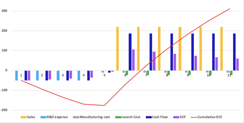
Fig.1: The NVP of our project from 2020 to 2030
References:
<ref>The Space Review, October 24, 2011, Propellant depots: the fiscally responsible and feasible alternative to SLS.
http://www.thespacereview.com/article/1955/1</ref>
<ref>Jonathan R. Stephens, NASA MSFC and Wesley L. Johnson, NASA GRC, in 2017. “Cryogenic Fluid Management, Technology Development Roadmap”</ref>
<ref>2017, DOE Hydrogen and Fuel Cells Program Review, Hydrogen Storage Cost Analysis Page 7.</ref>
In-Space Propellant Depot Technology Roadmap
2ISPD -In-space Propellant Depot
The below technology roadmap shows the roadmap to an in-space propellant depot based on the dates provided by the ULA for the centaur V rocket which should contain a type of in space propellant depot
Technology Strategy Statement
Our target is to develop an orbital propellant depot for methalox (methane and liquid oxygen) that becomes functional by 2022. To achieve a useful duration of 1000 days and a volume of 14 meters cubed we will invest in three research and development projects. The first is a cryocooler capable of over 150 watts cooling at 90 kelvin. The second is a multi-layer insulation that uses hard separators as opposed to a netting. The third is a composite, carbon fiber, storage tank for the cryogens used. These are enabling technologies that should allow us to reach our 2022 technical and business targets
