Laser Powder Bed Fusion - Metal
1. Roadmap Overview
This is a technology roadmap for: 3PEM - Proton Exchange Membrane This is a “Level 3” roadmap, indicating that it addresses a technology at the subsystem level. Higher level roadmaps related to this subject would address technology progression at the market level (Hydrogen Supply) and product level (Water Electrolyzer). A short video summary and introduction to this roadmap follows here.
{{#evt: service=youtube |id=https://youtu.be/JqCBwPOBRds }}
Technology Roadmap Sections and Deliverables
The clear and unique identifier for this technology roadmap is:
- 3LPB - Laser Powder Bed Fusion - Metal
This indicates that we are dealing with a “level 3” roadmap at the specific implementation level, where “level 1”and "level 2" would have indicated the over-arching roadmap and “level 4” would have indicated an individual technology roadmap.
In select sections of the roadmap, "3LPB" signifies a fictional company seeking to develop an improved LPBF-M machine.
Roadmap Overview
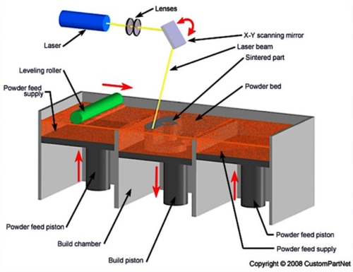
The working principle and architecture of Laser Powder Bed Fusion - Metal is depicted in the image below.
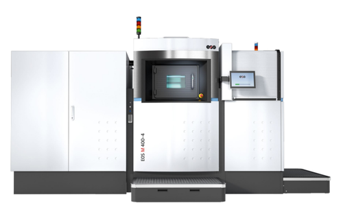
Figure: EOS M400-4 LPBF-M machine (source: EOS)
Figure: LPBF-M Process (source: CustomPartNet)
Laser Powder Bed Fusion - Metal (LPBF-M) is an additive manufacturing (AM) technology that enables the creation complex metal components directly from a digital 3D model without any tools. While the number of available materials is still limited compared to other milling and injection molding processes, LPBF-M utilizes various metals such as cobalt chrome, nickel alloys, titanium, aluminum, stainless steel and copper to generate robust functional prototypes and production parts that are capable of surviving in severe use cases. The LPBF-M technology offers comparable quality to parts made with traditional manufacturing methods, with material properties surpassing those of cast parts and approaching those of billet. It is most widely used in aerospace, medical, motorsports, energy, and molding. Beyond highly-stressed functional components, LPBF-M can be used for producing parts in cosmetic applications, manufacturing aids, small integrated structures, dental components, surgical implants.
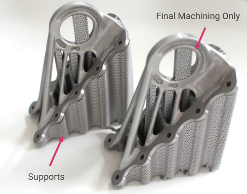
The process shares similarities with many other layer-wise additive manufacturing technologies. A program utilizes 3D model data and mathematically slices it into 2D cross-sections. Each section will act as a template that lets the LPBF-M machine know where to precisely create perimeters and cross-hatching. The data is transferred to the LPBF-M equipment. Subsequently, a "recoater" spreads a 25-120µm thick layer of powdered metal to produce a uniform layer over the solid metal build plate. A laser then draws a 2D cross-section on the powdered material, fusing the substrate into a solid. Once a layer is complete, the base plate is lowered enough to make room for the next layer. More material is collected from the reservoir and recoated evenly on the previously sintered layer. The LPBF-M machine continues to create layer upon layer building from the bottom up as the part is built. Support structures are added to part to provide a reinforcement for overhangs, and to prevent thermally expansion from negatively impacting dimensional accuracy. Following printing, the unfused powder is vacuumed from the chamber and the build plate is removed from the machine. Thereafter, the components typically undergo a stress relief and/or heat treatment process to remove residual thermal stresses and improve material properties. Following heat treatment, the next steps are support removal, detachment from the build plate (via bandsaw or wire EDM), and media blasting for final powder removal.
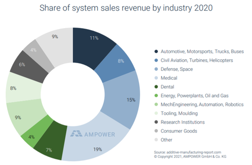
Figure: Industry breakdown for installed metal powder bed fusion machines. This figure includes non-laser powder bed machines but 85-90% of these unit sare LPBF-M. (source: Dr. Maximilian Munsch, AMPOWER 2021 Additive Manufacturing Report)
There is also an environmental advantage in the raw material efficiency of the processes. While the scrap rate for many complex milled parts is over 90%, the scrap rate for LPBF-M parts is typically less than 5%. While milled chips can be recycled, they must be processed offsite using considerable energy. In many cases, the LPBF-M powder can be immediately returned to a machine reservoir following sieving.
Figure: A350 XWB cabin brackets (source: Airbus)
The primary deficits of the technology in its current form are slow production rates, expensive machines, and high powder costs due to low volume requirements. The combination of these three challenges results in a high part piece cost. However, with improved performance, elimination of tooling, and reduced lead-time, there are many positive business cases for LPBF-M. In the future, the introduction of high-speed systems with more powerful lasers and larger build chambers is expected to increase the number of viable economically-viable applications that will drive increased demand and scale for LPBF-M systems.
Figure: Cost comparison for conventional manufacturing (CM), additive components, and AM-enhanced tooling. The freedom provided by AM methods like LPBF-M provides entry to design spaces that would otherwise be impractical or impossible to access. (source: Modified from John Hart and Haden Quinlan, MIT xPro "Additive Manufacturing for Innovative Design and Production course," MIT)
The LPBF-M market is maturing with breakthrough applications across multiple industries that provide the justification and institutional know-how to continue growing the technology.
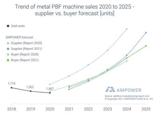
Figure: Metal powder bed fusion machines expected sales show a predicted 6000-7500 units by 2025. This figure includes non-laser powder bed machines but 85-90% of these sales are LPBF-M, bringing the predicted totals to 5100-6750. (source: Dr. Maximilian Munsch, AMPOWER 2021 Additive Manufacturing Report)
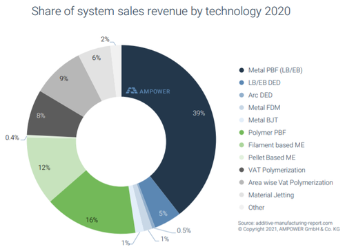
Figure: Metal powder bed fusion is responsible for 39% of sales revenue of all AM machines. While significantly more expensive than polymer systems (>2X), LPBF-M sales revenue is reflective of the technology's increasing foothold. (source: AMPOWER 2021 Additive Manufacturing Report)
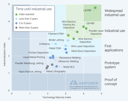
Finally, LPBF-M is the leading metal AM technology from an industrialization and technology maturity standpoint, yet it still has significant room for improvement, making it the ideal technology for roadmapping.
Figure: LPBF-M leads industrialization and technology maturity indices. (source: AMPOWER 2021 Additive Manufacturing Report)
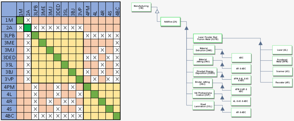
Design Structure Matrix (DSM) Allocation[edit]
The classification tree below shows us that LPBF-M is part of the larger Additive system. The DSM and tree both show that LPBF-M requires the following technologies at subsystem level 4: Laser (4L), Powdered Metal (4PM), Scanner (4S), Recoater (4R), and Build Chamber (4BC). Each level 3 subsystem also requires enabling technologies shown as level 4 systems.
Roadmap Model using OPM
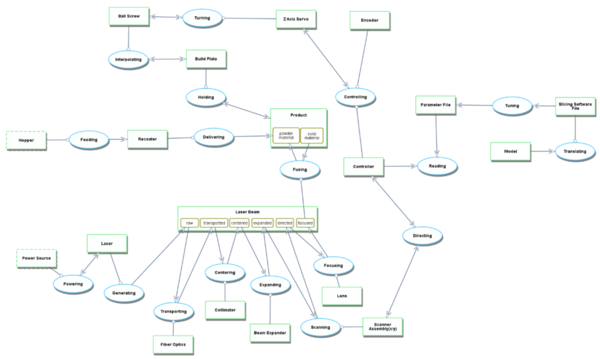
An Object-Process-Diagram (OPD) of LPBF-M is provided in the figure below. This diagram captures the main object of the roadmap (LPBF-M), its various instances including development projects, its decomposition into subsystems, its characterization by Figures of Merit (FOMs) as well as the primary processes.
Figure: Object-Process-Diagram for LPBF-M
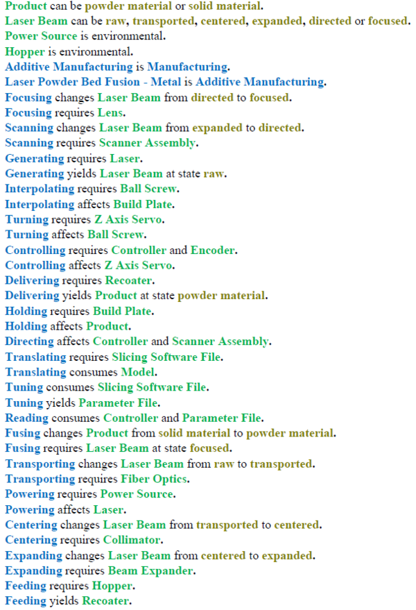
An Object-Process-Language (OPL) description of the roadmap scope is auto-generated and given below. It reflects the same content as the previous figure, but in a formal natural language.
Figure: Object-Process-Language for the LPBF-M OPM
The advantage is the excellent material efficiency of most additive manufacturing processes. While the scrap rate for many complex milled parts is over 90%, the scrap rate for LPBF-M parts is typically less than 5%.
With decreasing available raw materials and rising costs, this material efficiency will be a significant advantage in the long run. In the future, the introduction of high-speed systems with more powerful lasers and larger build chambers is expected to increase the share of LPBF-M in the production process, and a significant number of materials will become compatible with LPBF-M.
Design Structure Matrix (DSM) Allocation
The sentence will come here. The sentence will come here. The sentence will come here. The sentence will come here. The sentence will come here. The sentence will come here. The sentence will come here. The sentence will come here. The sentence will come here. The sentence will come here. The sentence will come here. The sentence will come here. The sentence will come here. The sentence will come here. The sentence will come here. The sentence will come here. The sentence will come here. The sentence will come here. The sentence will come here. The sentence will come here. The sentence will come here. The sentence will come here. The sentence will come here. The sentence will come here. The sentence will come here. The sentence will come here. The sentence will come here. The sentence will come here. The sentence will come here. The sentence will come here. The sentence will come here. The sentence will come here. The sentence will come here. The sentence will come here. The sentence will come here. The sentence will come here. The sentence will come here. The sentence will come here. The sentence will come here. The sentence will come here. The sentence will come here. The sentence will come here. The sentence will come here. The sentence will come here. The sentence will come here. The sentence will come here. The sentence will come here. The sentence will come here. The sentence will come here. The sentence will come here. The sentence will come here. The sentence will come here. The sentence will come here. The sentence will come here. The sentence will come here. The sentence will come here. The sentence will come here. The sentence will come here. The sentence will come here. The sentence will come here. The sentence will come here. The sentence will come here. The sentence will come here. The sentence will come here. The sentence will come here. The sentence will come here. The sentence will come here. The sentence will come here. The sentence will come here. The sentence will come here. The sentence will come here. The sentence will come here. The sentence will come here. The sentence will come here. The sentence will come here. The sentence will come here. The sentence will come here. The sentence will come here. The sentence will come here. The sentence will come here. The sentence will come here. The sentence will come here. The sentence will come here. The sentence will come here. The sentence will come here. The sentence will come here. The sentence will come here. The sentence will come here. The sentence will come here. The sentence will come here. The sentence will come here. The sentence will come here. The sentence will come here.
Roadmap Model using OPM
We provide an Object-Process-Diagram (OPD) of the 2LPBF-M roadmap in the figure below. This diagram captures the main object of the roadmap (Laser Powder Bed Fusion - Metal), its various instances including development projects, its decomposition into subsystems, its characterization by Figures of Merit (FOMs) as well as the main processes.
An Object-Process-Language (OPL) description of the roadmap scope is auto-generated and given below. It reflects the same content as the previous figure, but in a formal natural language.
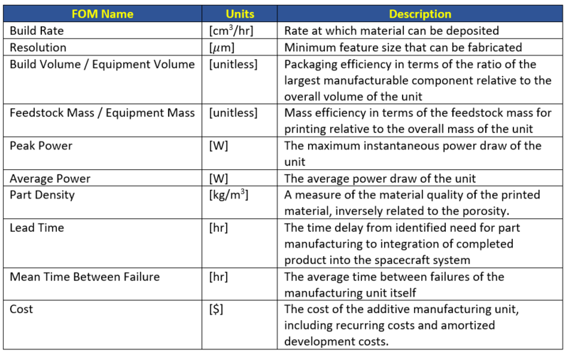
Figures of Merit
The table below shows a list of FOMs by which Laser Powder Bed Fusion - Metal can be assessed. The sentence will come here. The sentence will come here. The sentence will come here. The sentence will come here. The sentence will come here. The sentence will come here. The sentence will come here. The sentence will come here. The sentence will come here. The sentence will come here. The sentence will come here. The sentence will come here. The sentence will come here. The sentence will come here. The sentence will come here. The sentence will come here. The sentence will come here. The sentence will come here. The sentence will come here. The sentence will come here. The sentence will come here. The sentence will come here. The sentence will come here. The sentence will come here. The sentence will come here. The sentence will come here. The sentence will come here. The sentence will come here. The sentence will come here. The sentence will come here. The sentence will come here. The sentence will come here.
Positioning of Company vs. Competition
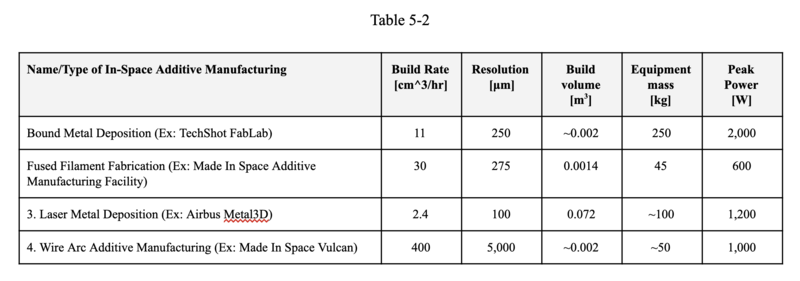
We compared and organized the FOM from related/competitive companies. Some key data/info is confidential, therefore we will keep it blank.
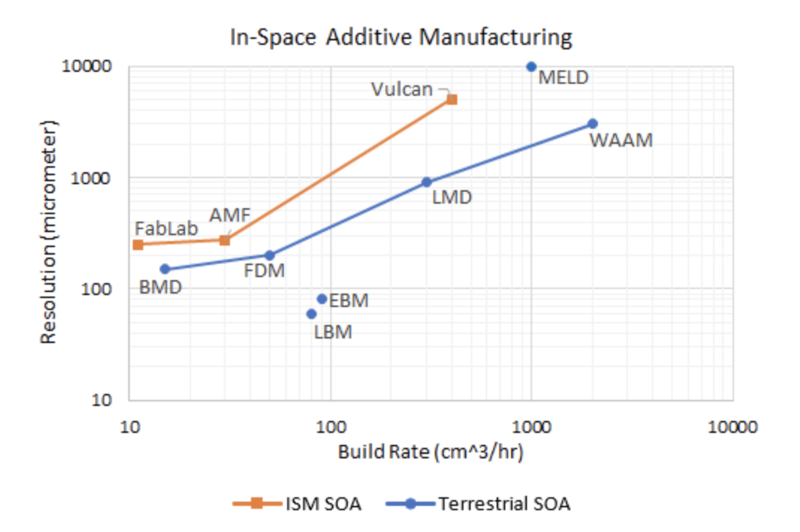
The following figure is the Pareto Front of Resolution vs. Build Rate for Various Additive Manufacturing Processes
The utopia point for the chart above is on the bottom right corner and at-present the Pareto front for Terrestrial SOA is closer to the utopia point than for ISM SOA. The parts which we will be manufacturing in space need to be of high quality and should have a reasonable manufacturing time. If the parts produced in space have a much lower resolution (higher micrometers) and have a low build rate (and consequently high build times and mean times to failure), then the manufactured parts may be unusable and provide minimal advantage over manufacturing on earth. The focus here is to shift the Pareto front for ISM SOA closer to the utopia point which can be achieved by maximizing resolution (lower micrometers) and build rate within reasonable limits. Working on improvements in both areas align with our strategic drivers and will help us achieve our goals within the target dates specified in the Technology Strategy Statement mentioned in the latter section.
While there are many technically feasible approaches to additive manufacturing of parts and systems, not all are adaptable to space. Present limitations for in-space manufacturing which contribute to the differences in the Pareto front for resolution and build rate include -
- Space systems engineering is a complex discipline with very mature methods of certification which results in the deployment of extensively tested apparatus. Due to the extensiveness of testing before sending it to space, AM technologies have been progressing faster for terrestrial applications.
- Current additive manufacturing systems deliver accurate and precise results in a 1 g, thermally controlled environment and are well understood. The same level of information is not available for ISM as there is much more testing for terrestrial AM due to less stringent certification methods.
- Current processes such as photolithography can create electric components at scales of 35 nanometers as compared to common AM resolution (>50 microns) which would produce components 1,000 times larger than the physical size of currently available parts. This disparity in performance discourages investment by organizations to conduct research in this area.
- Physics-based models of in-space additive manufacturing processes are needed to understand and predict material properties and help optimize material composition.
- The thermal effects of energy source and energy density in space has not yet been extensively researched.
- There is not enough investment in systems that produce open-system design, planning, simulation, and analysis tools for ISM.
- Design for and construction of objects in space will likely require much less mass, due to the reduced gravity, but it is difficult to predict the overall mass reduction and corresponding impact on construction time without knowing the resolution required and the impact of other environmental effects on the process.
- The impact of vacuum and thermal environments on the AM technology is not holistically understood due to a lack of data.
References:
