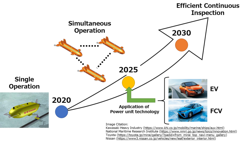
Autonomous Underwater Vehicle
Technology Roadmap Sections and Deliverables
The unique identifier of this technology roadmap is:
- 2AUVOPI - Autonomous Underwater Vehicle for Offshore Platform Inspection
This indicates that we are dealing with a “level 2” roadmap at the product or system level, where “level 1” would indicate a market level roadmap and “level 3” or “level 4” would indicate an individual technology roadmap.
Roadmap Overview
The offshore platforms are the oil and gas production facilities that are located offshore. In the past, oil and gas were generally produced on the ground. However, as the number of fossil fuel-rich sites that were accessible from the ground has been limited, offshore oil and gas development has been important. In 2016, there were more than 3,000 offshore oil and gas production facilities in the world, and it is estimated that the number of facilities will increase.<ref>International Energy Agency (IEA), Offshore Energy Outlook (2018), https://webstore.iea.org/download/direct/1034</ref>
The offshore platform has a lot of subsea structures such as pipelines, so the inspection and maintenance of these structures is a very important issue. However, some platforms are installed in water depths of more than hundreds of meters, so it is impossible for humans to dive and inspect these structures. In order to overcome this problem, Remotely Operated Vehicles (ROVs) are widely used. ROVs are unmanned vehicles that are connected to the mothership by a wire and can be manipulated by operators who are boarding in the mothership. In addition, ROVs can get power through the wire, so they can be operated for a long time. However, ROVs have many problems such as motion limitation caused by the wire.
On the other hand, the Autonomous Underwater Vehicles (AUVs) don't have wires, so the operation flexibility is the great advantage of AUVs. In order to take advantage of this strength of flexibility, securing the accuracy of position sensing is important for AUVs. Meanwhile, the capacity limit of the power source is the weak point of AUVs, so it is a challenge for AUVs to exchange each vehicle smoothly before the energy capacity becomes empty or to extend the operating time of each vehicle.
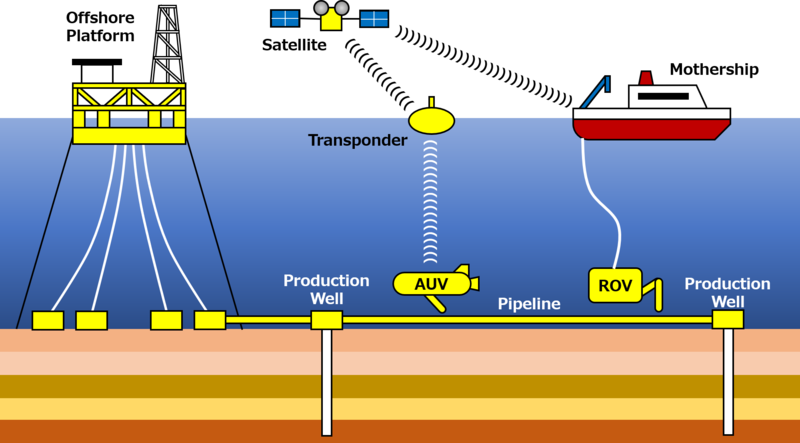
The overview of the AUVs operation in the offshore platform is as below. The AUVs inspect the subsea structures such as pipelines automatically and they can communicate with the operators in the mothership through the transponders and satellites.
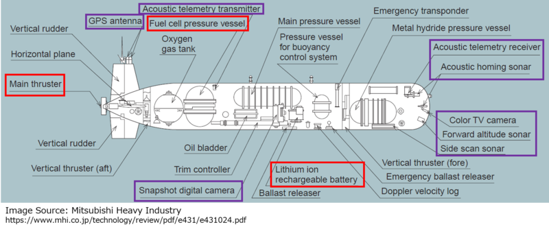
The general arrangement of AUV's mechanical components is as below. Typical AUVs look like a submarine, and they have thrusters and power sources that are necessary to move in the water. In the water, the amount of air that can be used for the combustion of fuel is very few, so a battery or fuel cell is generally used as a power source of AUV. In addition, there are some sensors and communication systems such as sonar, camera, and acoustic system, and they are very important to move underwater automatically and inspect the subsea structures.
Design Structure Matrix (DSM) Allocation

The above 2AUVOPI tree shows the relationship between some systems related to the AUV that uses the battery as a power source. This tree says that the AUV for offshore platform inspection (2AUVOPI) is one of the methods of the offshore platform inspection and consists of the vessel (3VES), thruster (3THR), power source (3POW), position sensing device (3PSD), communication device (3COD), and inspection device (3IND) subsystems. These subsystems require following components: composite (4COM), screw (4SCR), electric motor (4EMO), battery (4BAT), GPS antenna (4GPS), sonar (4SON), acoustic communication device (4ACD), camera (4CAM), inspection sensor (4INS).
Roadmap Model using OPM
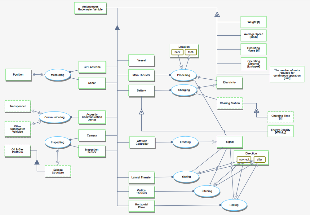
We provide an Object-Process-Diagram (OPD) of the 2AUVOPI roadmap as below. As this diagram shows, the object of this roadmap (AUV) consists of subsystems such as thrusters, battery, controller, sonar, and sensor. These subsystems are organized for the movement in the water, the inspection of subsea structures, and the communication with other underwater vehicles. In addition, some indicators that characterize the performance of AUV are also shown in this diagram, and these indicators are some of the Figure of Merit (FOM).
An Object-Process-Language (OPL) description that is generated automatically is as below. The content of this OPL is the same as the above OPD.
Figures of Merit (FOMs)
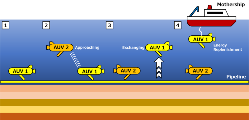
For the oil & gas offshore platform operators, the inspection of subsea structures is very important in order to secure safety. However, a large amount of inspection cost loses profitability, so it is important to minimize the inspection cost by making the inspection efficient. As we mentioned in the above "roadmap overview" section, AUV is suitable for the subsea structure inspection because of its flexibility. In order to make the inspection effective and efficient, AUV has to move accurately in the sea, so the accuracy of position sensing is important. In addition, AUVs have the capacity limitation of power source, so it is necessary to replenish the energy source periodically. However, if the inspection is interrupted in every replenishment, the efficiency of inspection is greatly reduced, so it is important to achieve a "continuous inspection system". In order to achieve this "continuous inspection system", it is necessary to exchange each AUV smoothly for energy replenishment, so the simultaneous operation of several AUVs is the key technology. If this simultaneous operation becomes possible, as the below figure shows, when an AUV's battery is low, a replacement AUV can approach automatically and take over the mission smoothly. Furthermore, if we can reduce the number of AUVs that are necessary for the inspection as much as possible, the capital cost will decrease, so the extension of the operating hours of each AUV is also important.
The below table is a list of typical FOMs related to the key issues (Position Sensing, Simultaneous Operation, and Extension of Operating Hours) that we mentioned above.
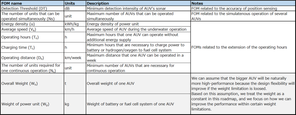
The below table shows the relationship between several FOMs related to the extension of the operating hours.

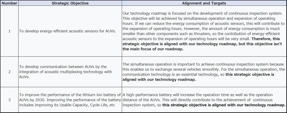
Alignment with Company Strategic Drivers
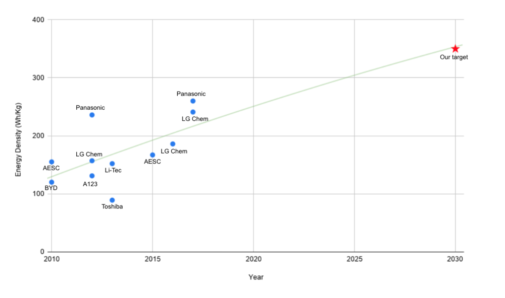
Positioning of Company vs. Competition
source: https://www.osti.gov/pages/servlets/purl/1561559
Technical Model
As we mentioned above, the sonar and power unit (Battery or Fuel Cell) are examples of important components to achieve a continuous inspection system that uses AUVs, so we explain related technical models.
Sonar
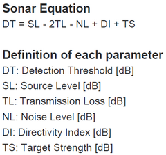
The key FOM of sonar is the “Detection Threshold (DT)”, and the technical equation of DT is as below.
Below is the normalized tornado chart that shows the sensitivity of each parameter to DT.
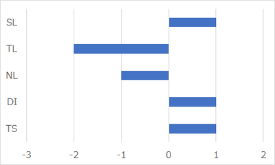
As this chart shows, TL is the most sensitive parameter. However, it is impossible to change TL and NL because these parameters are determined by the composition and depth of seawater. In addition, TS depends on the character of the inspection target, so we can’t also change this parameter. If we increase SL, DT will be improved, but it needs more energy in order to increase SL. This method may not be effective for AUV because the energy capacity of AUV is limited. On the other hand, DI can be improved by changing the directivity of the receiver, and this improvement would have minimal impact on other components of AUV, so this approach may be effective to improve DT.
Battery
The key FOM of the battery is the “Energy Density (u)”. In this section, we treat the theoretical energy density of the battery, and its technical equation is as below.

Below is the normalized tornado chart that shows the sensitivity of each parameter to energy density.
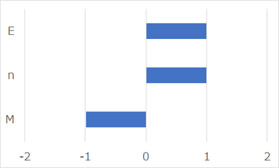
As this chart shows, "E", "n", and "M" have almost the same sensitivity for the theoretical energy density of the battery. In order to increase the energy capacity, we should increase "E" and "n" or decrease "M". "E" is determined by the electric potential difference between cathode and anode, so if we select high electric potential material for cathode or low electric potential material for the anode, "E" will be improved. However, when "E" becomes larger than 4.2 [V], there is a problem that the electrolyte in the Li-ion battery is decomposed. In order to solve this problem, we should develop a new electrolyte that can withstand high voltage. In addition, if we increase "n" and decrease "M" by developing light material that contains a lot of Li-ion, theoretical energy density will improve. In any case, in order to improve the energy density of the battery, it is necessary to develop new materials. The development of new material needs a lot of resources and investment, so outsourcing will be one of the options for us.
Fuel Cell
One of the expected power source of AUV is a fuel cell. If we want to increase the energy capacity of a fuel cell, it is necessary to increase the amount of hydrogen storage. However, the space capacity of AUV is limited, so increasing the pressure of the stored hydrogen, rather than making the dimension of the hydrogen tank larger, would be effective. The relationship between the hydrogen pressure and the tank dimension is below.
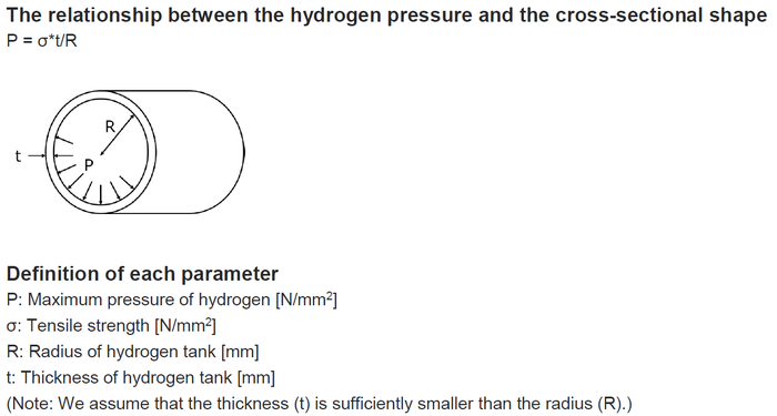
If we can’t change the overall dimension of the hydrogen tank because of the AUV's size limitation, the variables that can be changed are “σ” and “t” in order to increase the hydrogen capacity. Below is the normalized tornado chart that shows the sensitivity of “σ” and “t” to the maximum hydrogen pressure.
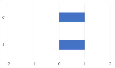
As this chart shows, “σ” and “t” have the same sensitivity for maximum hydrogen pressure. However, if we increase “t”, this directly leads to increasing the hydrogen tank weight. In order to avoid weight increase, it is effective to increase“σ”by changing the material of the hydrogen tank.
Key Publications and Patents
Publications
Title: S.G. Chappell, et al. "Acoustic communication between two autonomous underwater vehicles" IEEE Symposium on Autonomous Underwater Vehicle Technology (1994)
Executive Summary: This paper describes a project designed to investigate and demonstrate communication between two autonomous underwater vehicles (AUVs). This paper presents the results of in-water field experiments in which two AUV systems were able to communicate with each other using acoustic modems while conducting a simple mission.
Link
Title: "A battery-free sensor for underwater exploration" MIT News (2019)
Executive Summary: This article talks about the battery-free underwater communication system that uses near-zero power to transmit sensor data developed by MIT researchers. The system makes use of two key phenomena. One, called the “piezoelectric effect,” occurs when vibrations in certain materials generate an electrical charge. The other is “backscatter,” a communication technique commonly used for RFID tags, that transmits data by reflecting modulated wireless signals off a tag and back to a reader.
We believe that technologies like this can completely revolutionize the AUVs capabilities.
Link
Title: Bruno Scrosati, Jürgen Garche. "Lithium Batteries: Status, Prospects and Future" Journal of Power Sources (2010)
Executive Summary: This review focuses first on the present status of lithium battery technology, then on its near future development and finally it examines important new directions aimed at achieving quantum jumps in energy and power content.
Link
Patents
Title: Byrd, et al. (2019) "Underwater vehicle for inspection of a subsea structure in a body of water and related method"
Executive Summary: The invented AUV has a body like a torpedo and this AUV can sail safely at a certain distance from the pipelines. In addition, this AUV has 2 sensors on the upper and lower side of its body, and these sensors enable us to detect problems such as corrosion in the pipelines nondestructively.
Link
Title: Ilia Vainstein, et al. (2004) "Wireless underwater communication system"
Executive Summary: This patent relates to a wireless underwater (UW) communications system for real-time transmission of video, control, and data-communications between underwater vehicles; or between an underwater vehicle and a surface platform; between underwater platforms; or the likes.
Link
List of R&D Projects
Summary
Our goal is the establishment of an AUV system for continuous inspection of oil and gas offshore platforms. This will be able to contribute to providing efficient inspections and making platforms safe.
However, because the energy capacity of each AUV is limited, it is necessary to put the multiple AUVs into the mission by turns.
In order to achieve a seamless inspection, it is important to communicate between each AUV and take over the mission smoothly, so the establishment of communication technology between AUVs is an important R&T topic.
In addition, the longer the hours an AUV can operate per one mission, the more cost-effective it becomes because we can reduce the number of AUVs that are necessary to be deployed for replacement.
Therefore, we think that the extension of AUV's operating hours is also an important R&T issue.
By the way, as we show in the "technical model" section, the detection threshold of sonar is determined by the directivity of the receiver. We think that the improvement of the directivity is not an R&D issue but a matter of setting of the sonar equipment, so we excluded the sonar from the R&D list.
Communication technology between AUVs
Currently, AUVs for oil and gas platform inspection are in practical use, but they are operating independently.<ref>Kawasaki Heavy Industries, Autonomous Underwater Vehicle (AUV) “SPICE”, http://www.khisubsea.co.uk/autonomous-underwater-vehicle/</ref>
If we want to operate several AUVs simultaneously, acoustic multiplexing technology is necessary as a communication method, and this technology has recently been matured.<ref>JAMSTEC, Next-generation technology for ocean resources exploration, https://www.jamstec.go.jp/sip/en/pdf/brochure.pdf</ref>
Based on this situation, our first goal is the integration of acoustic multiplexing technology with AUVs for oil and gas platform inspection.
We plan to take five years for this challenge.
Extension of AUV's operating hours
The extension of AUV's operating hours will be achieved by the development of battery technology or fuel cell technology.
These technologies require a lot of resources, so it is difficult to build everything up from scratch. Fortunately, the technology competition between battery and fuel cell has been progressing in the automobile field, so we will be able to apply the result of R&T of the automotive.
In our analysis, we think that both Li-ion battery and fuel cell are promising energy source for AUV at present.
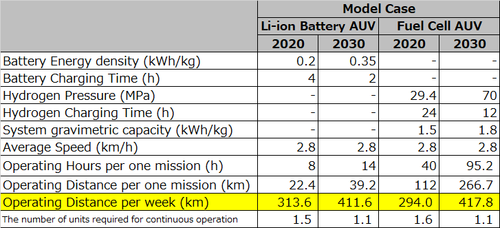
Based on the battery-powered and fuel-cell-powered AUVs that were built so far, we made model cases in 2020 and 2030 as follows.
<ref>Kawasaki Heavy Industries, https://www.khi.co.jp/stories/articles/vol99/</ref>
<ref>Toshio Maeda et al, Fuel Cell AUV "URASHIMA", Mitsubishi Heavy Industries, Ltd. Technical Review Vol.43 No.1(Jan.2006), https://www.mhi.co.jp/technology/review/pdf/e431/e431024.pdf</ref>
<ref>Reinhardt Wagner, Battery Fuel Gauges: Accurately Measuring Charge Level (2006)</ref>
<ref>DOE, Target Explanation Document: Onboard Hydrogen Storage for Light-Duty Fuel Cell Vehicles (2017), https://www.energy.gov/sites/prod/files/2017/05/f34/fcto_targets_onboard_hydro_storage_explanation.pdf</ref>
At present, the performance of battery and fuel cell are in competition (Battery (313.6(km/week)) VS Fuel Cell (294.0(km/week))). In addition, the performance improvement expected in 2030 is also in competition (Battery (411.6(km/week)) VS Fuel Cell (417.8(km/week))). Therefore, we think that narrowing down power unit candidates to either battery or fuel cell is not a good idea at this time.
However, these predictions are just model cases, so the situation may change significantly depending on future technological developments.
Therefore, we plan to keep following up on the development trends of power unit until 2025, decide which technology is suitable for our AUV in 2025, and install the power unit in 2030.
R&T schedule
The overall R&T schedule is as below. We set a stage-gate in 2025 and are going to decide whether we should expand our project or not.

Financial Model
Based on the above R&T schedule, we analyzed the financial feasibility of our project.
Our strategy has two stages. In the first stage, we conduct R&T of acoustic communication technology and start selling AUVs with this technology in 2025.
In the second stage, we conduct R&T of battery or fuel cell technology and start selling AUVs with new power units in 2031.
Based on the evaluation results about the power unit scheduled in 2025, we will be able to choose between the following two models.
1) Conservative model: We don't invest in the R&T of the power unit, and we continue to sell only AUVs with acoustic communication technology. In this case, the operation hours of this AUV remain short, so the unit price will be low and the number of sales will be small (1 million$/unit, 10 unit/year) because of the low competitiveness.
2) Optimistic model: We decide to invest in the R&T of the power unit, and we will start to sell the AUVs with new power units in 2031. In this case, the operation hours of this new AUV will be long, so the unit price and the number of sales will increase (1.2 million$/unit, 20 unit/year) based on the high competitiveness.
Based on the similar projects of AUV's communication technology, we estimated that the R&T cost of acoustic communication technology is 10 million $. This cost covers the design, 2 prototype AUVs production, field test, and improvement. The manufacturing cost of 2 prototype AUVs will be the most expensive (5 million $). In addition, we estimated that the R&T cost of the power unit is 8 million $. We plan to divert the prototype AUVs for acoustic communication technology to the R&T of the power unit, and this will lead to cost-saving of R&T. In both models, we expect a learning effect on productivity. We assume that the initial profit margin is 20%, and the profit margin improves by 1% each year. Furthermore, we assume that the discount rate is 7% that is general in the R&D project, and calculate the Net Present Value (NPV) by 2040. Based on these assumptions, we analyzed the financial forecast as follows.
Financial forecast of conservative model
Financial forecast of optimistic model
As these results show, even if we choose the conservative model, the NPV is positive (11.1 million $). This means that the conservative model is profitable. However, the optimistic model is more profitable (NPV: 16.7 million $), so it can be mentioned that the stage-gate related to the power unit scheduled in 2025 is very important for our project because this will determine whether we can maximize profits or not.
Technology Strategy Statement
As we mentioned above, our goal is the establishment of an AUV system for efficient continuous inspection of oil and gas offshore platforms in 2030. In order to achieve this goal, we will invest in two R&T projects. The first is the integration of acoustic multiplexing technology with AUVs, and we plan to succeed in the coordinated simultaneous operation of multiple AUVs until 2025. The second project is the extension of AUV's operating hours. Our strategy is to apply the technology of the automobile industry to AUVs, so we plan to assess the development trends of the automobile power unit in 2025 and integrate the selected technology into the AUVs in 2030. This will enable us to maximize the operating hours and minimize the number of AUVs which are necessary to the continuous inspection mission.
References
<references />
