Detect And Avoid Autonomous Augmentation System
1. Roadmap Overview
This is a technology roadmap for: 3PEM - Proton Exchange Membrane This is a “Level 3” roadmap, indicating that it addresses a technology at the subsystem level. Higher level roadmaps related to this subject would address technology progression at the market level (Hydrogen Supply) and product level (Water Electrolyzer). A short video summary and introduction to this roadmap follows here.
{{#evt: service=youtube |id=https://youtu.be/mfDTZW8ekyg }}
ROADMAP OVERVIEW
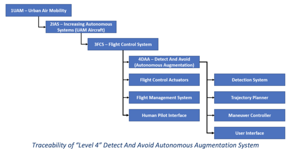
The technology selected consists of a Detect And Avoid Automated Augmentation System (DA4S). The system is intended to augment Urban Air Mobility (UAM) pilots in their responsibility to see other air traffic and maneuver to remain well clear of them [14 CFR Part 91]. As studied in this roadmap, this is a “Level 4” technology (4DAA), where “Level 1” is the market level for Urban Air Mobility (1UAM), “Level 2” are the Increasingly Autonomous System (IAS) aircraft found in UAM (2IAS), and “Level 3” is the flight control system (3FCS). Even though our roadmap targets this for the UAM market, it is noted that the technology is applicable to many General Aviation (GA) aircraft.
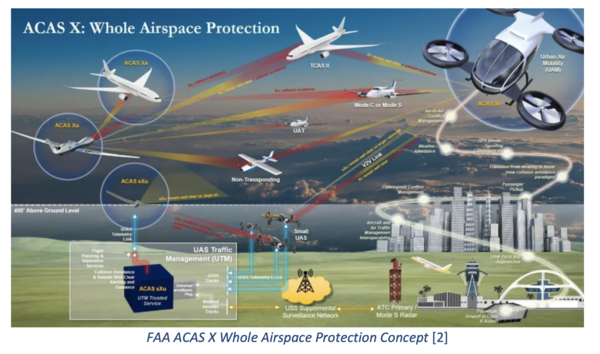
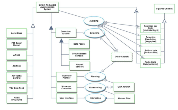
Detect And Avoid (DAA) is a significant challenge in emerging aviation markets such as integrating Unmanned Aircraft Systems into the National Airspace System, or increasing the density of air traffic as envisioned in UAM [1]. The DA4S technology is intended to support the pilot by performing four main functions: (1) help detect and track other air traffic, (2) plan trajectories to remain well clear of the traffic and satisfy other flight constraints, (3) issue control commands into the aircraft autopilot to maneuver the aircraft along the selected collision resolution trajectory, and (4) interface with the pilot. Each of these functions are enabled through a suite of integrated subsystems. The technology is intended to be aircraft agnostic, and be able to be integrated into any small piloted GA or UAM aircraft. The system augments the pilot in performing DAA, but does not replace him/her. The pilot retains the ability to visually detect, plan, and perform their own evasive maneuvers. The pilot may also work with the DA4S autonomy in any of its first three functions to improve the overall system output. For example, the pilot may input traffic they detect themselves, tune trajectory planning parameters, and assist in selecting the best resolution. The figure below shows the OV-1 diagram for the ACAS Xr system, which is one of the technologies being pursued to assist in DAA for UAM aircraft, and visually represents some of the considerations for the roadmapped DA4S technology.
DESIGN STRUCTURE MATRIX (DSM)
ROADMAP MODEL USING OPM
FIGURES OF MERIT
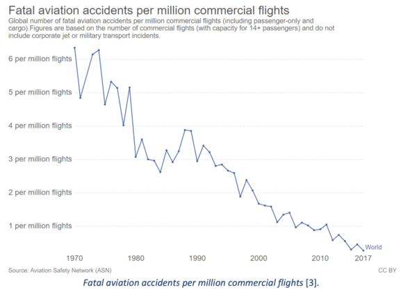
One of the critical FOMs that we are looking at are the number of fatal accidents per million flights. Ultimately what DA4S aims to accomplish is increase flight safety in a future combined environment where there will be both crewed and autonomous flight vehicles. This is also one of the most well historically documented pieces of flight data that we have and is maintained by the National Transportation Safety Board (NTSB) [3]. The absolute limit would be zero fatalities for any flight. This would likely be extremely difficult to achieve. However, there is still plenty of room for improvement as there are still numerous fatalities every year. Unlike performance FOMs which typically seek to increase their metric, safety systems tend to be inverse as the utopia point is zero. This trend more closely resembles an S-curve. As we can see in Error! Reference source not found., there was a takeoff in airline safety in the mid-1970s. Then a slowing in the 1980s which has led to somewhat of a stagnation since 2015. Since 1970 this FOM has exhibited an annual rate of progress of 0.12 reduction in fatalities per million commercial flights through 2017. In terms of technology lifecycle of flight safety, we take consider visual flight rules being first generation, instrumentation flight being second generation, electronic/computer aided flight as the third and current generation. DA4S would introduce a leap forward in the next generation of flight safety with the implementation of autonomous safety systems. A future FOM will also be derived utilizing smaller craft hazard reports from commuter and on-demand flight operations conducted under 14 Code of Federal Regulation (CFR) Part 135.
ALIGNMENT WITH COMPANY STRATEGIC DRIVERS
POSITIONING OF COMPANY VS. COMPETITION
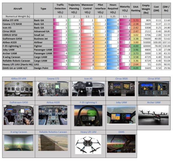
The following figure compares the DA4S system against its competitors for the following considerations: (1) traffic detection capability, (2) trajectory planning capability, (3) mechanism to control maneuvers, (4) pilot interface, (5) hours required to pilot such an aircraft, and (6) maturity of the system. The mechanism used to create this comparison is described in the technical model section. A broad variety of aircraft was included in this analysis in an effort to capture the trade with respect to the overall field of aviation. Aircraft included in the analysis include small and larger GA aircraft, a variety of business jets, an airliner, a 5th generation fighter jet, unmanned aircraft, and Urban Air Mobility concepts. A visual comparison of their flight deck technologies is shown below.
TECHNICAL MODEL
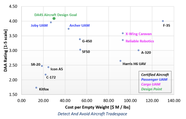
The following figure plots the tradespace of aircraft in terms of their Detect And Avoid augmentation capabilities compared to a broad variety of other aircraft. The vertical axis represents a Detect And Avoid rating systematically derived for each aircraft using the following considerations: (1) traffic detection capability, (2) trajectory planning capability, (3) mechanism to control maneuvers, (4) pilot interface, (5) hours required to pilot such an aircraft, and (6) maturity of the system. The horizontal axis represents the cost per empty weight of such aircraft. Since the DA4S is intended to augment pilots of General Aviation (GA) and Urban Air Mobility (UAM) aircraft, the design point utopia is to the top left of the chart (high DAA rating with low cost per empty weight). Unsurprisingly, this design point of DA4S is in the vicinity (but outperforms) several existing UAM prototypes.
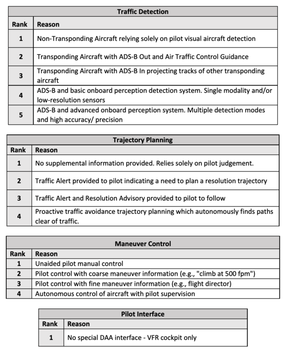
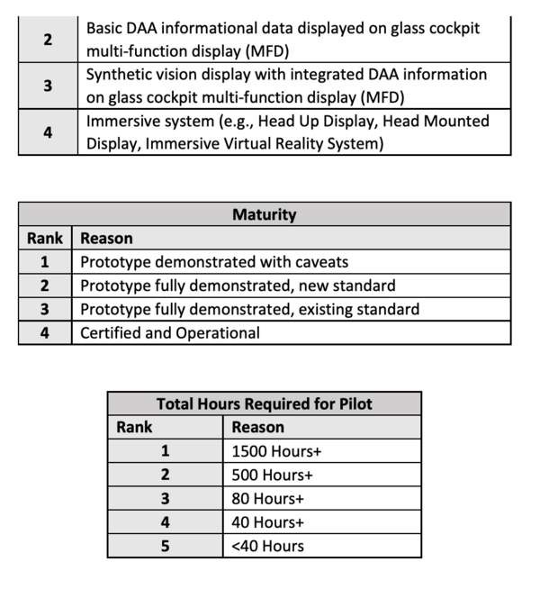
The Empty Weight and Cost data for each aircraft were obtained using internet searches. The Detect And Avoid rating was systematically derived for each aircraft to capture attributes of importance to our technology. These attributes are reflective of the four main functions of the DA4S system: (1) traffic detection capability, (2) trajectory planning capability, (3) mechanism to control maneuvers, (4) pilot interface. In addition, two attributes were included to capture aircraft complexity of operation using (5) hours required to pilot such an aircraft, and (6) maturity of the system. Performance scores for each of these ratings were obtained using the specifications listed in the 6 tables below given expert knowledge of the aircraft assessed by our team members (2 of the team members are experienced pilots). These
6 different scores were combined into a unique rating using the following Multi-Attribute Utility Analysis Equation.
where (Ji) represents each of the six attribute scores from the tables above. ki represents normalizing weights, representing the relative important of each attribute.
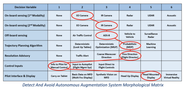
The following figure below represents the Morphological Matrix for the DA4S technology. The circled items consist of one possible configuration embodiment. The forms chosen for each function are consistent with a solution that would meet the standards of the ACAS-X standards in development for GA, UAM, and UAS aircraft (see Paper 1). On-board EO/IR sensing is provided as a supplement to ADS-B widely available today, and provides a day and night detection capability that can plug and play into the broader surveillance concept of ACAS- X. A probabilistic trajectory planning algorithm is implemented using Markov Decision Processes as done with ACAS-X. It is assumed that the GA and UAM aircraft that will seek this technology will be equipped with Multi-Function Displays (MFD) as part of a glass cockpit into which the DA4S information can be integrated. DAA information will be integrated into a Synthetic Vision application as currently available for Instrument Flying on some GA aircraft. DAA information can further be projected onto a simple head mounted unit to provide additional immersion to the pilot. Resolution Advisories will be coupled to the Flight Director on the MFD to provide the pilot with low level attitude control guidance to execute the maneuvers. In order to keep the DA4S system as a “bolt on” system that can be integrated into any aircraft, we decided to leave the control inputs to be performed by the human pilot, which will follow directions provided by our system. This too is consistent with current implementations of ACAS-X.
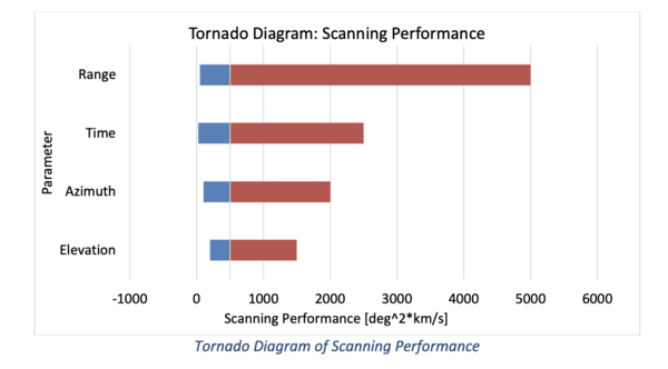
The two FOMs highlighted in the sensitivity analysis are scanning and tracking. Scanning is the ability for the DAA system to survey the environment around the aircraft. Scanning performance is influenced by the Azimuth (A, degrees), Elevation (E, degrees), Range (R, kilometers), and Time (T, seconds). These factors determine the overall scanning ability in the equation below.
For the sensitivity analysis we will use the estimated minimum and maximum expected bounds that the system will be exposed to in the table below. The higher the sensitivity performance, the better it is for DAA.
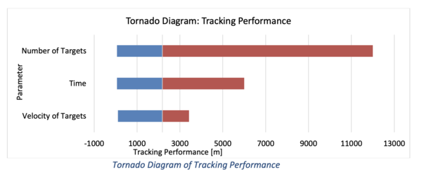
In terms of scanning performance as a FOM, range of the DAA is the most sensitive on the system. In order to achieve the greatest performance for the system. One should try to optimize DAA to achieve the greatest sensing range. This makes sense as you increase the envelope in which you have more situational awareness. The ability to detect hazards goes up tremendously. Tracking performance is determined by the number of vehicles within the same shared airspace as the aircraft DAA is equipped on. Tracking performance is dictated by the following parameters – Number of Targets (N, dimensionless), Velocity of Targets (V, m/s), and Time (T, seconds). The relationship is depicted in the equation below.
For tracking performance, the system is most sensitive to the number of targets that are being tracked. The duration of which it is being tracked is second most sensitive while the velocity of the target is less relevant. This makes intuitive sense as the most important thing to know is if another party is sharing your airspace and where it is located. The velocity of the target is supplemental information as you could avoid the targets’ general location with its initial position information.
FINANCIAL MODEL
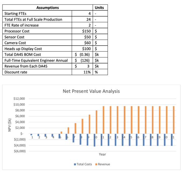
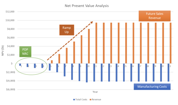
The financial model assumes an initial employment of four engineers with initial Product Development Project (PDP) period of four years from 2021-2024 as two more employees are added each year while the product is matured. This period will produce the first initial prototypes and be refined with beta testers. The first full retail product will be available in 2025 (year 5) which sets an expectation of 250 units being sold. The DA4S experiences further improvements, adoption, and enhancements with future features being integrated in 2027 and 2030. By 2031 (year 10) the product will have reached full-scale production.
LIST OF R&D PROJECTS
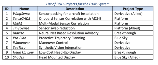
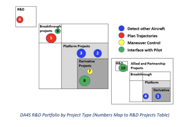
The ability to successfully develop and launch the Detect And Avoid Autonomous Augmentation System (DA4S) is dependent on its R&D Portfolio. The DA4S system supports four fundamental functions: (1) detect other aircraft, (2) plan trajectories, (3) maneuver the aircraft, and (4) interface with the pilot. As such, the R&D portfolio is diversified to span these functions at a variety of Technology Readiness Levels to support multi-generational growth of the system. The following is a list of 10 projects that are part of our portfolio. These are plotted on the R&D Portfolio framework based on their project type in the figure below.
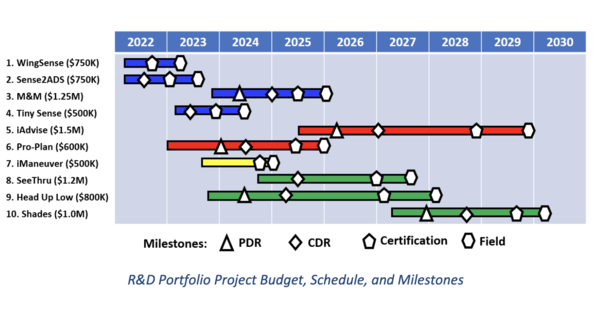
The R&D Portfolio Plan, including the budget, schedule, and milestones associated with each individual project is shown below.
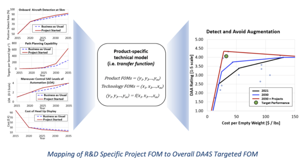
The figure below maps how the Figures of Merit (FOM) of some of the projects above transfer to the higher level FOM of the overall DA4S system based on the Technical Model previously described in the Technology Roadmap. The figure represents the current expected progress of each FOM without our R&D efforts and compares it to improvements expected from our R&D. The right side of the plot represents the overall DAA Rating FOM found in aircraft today (2021), what the expected market status is without our participation by 2030, and how our R&D projects can improve this state and achieve our targeted design point. The R&D Portfolio Plan, including the budget, schedule, and milestones associated with each individual project is shown below.
