Superconducting Cable
Technology Roadmap Sections and Deliverables
- 3SC - Superconducting Cable
Roadmap Overview
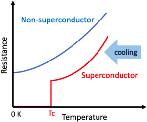
The feature of the superconductivity phenomenon, the basis of this roadmap technology (3SC - Superconducting Cable), is an unusual property of certain substances, including metals, alloys, and ceramics, in which electrical resistance drops to zero when the temperature is reduced below a critical temperature (Tc), as shown in the Right-sided graph. In contrast, in the case of the other normal materials, electrical resistance decreases as the temperature is lowered but does not disappear completely.
The roadmap technology is the superconducting cable, which is the cable incorporated by some material that can show superconducting phenomenon (i.e., superconductors or superconducting material) to be designed for conducting electricity with zero resistance. (It is classified under the "Transporting Process (2)" and the "Energy (E)" categories in 5x5 matrix.) The technology is pivotal for mitigating energy losses inherent to electrical resistance, which is crucial for efficiency and operational cost reduction, especially in the context of long-distance power transmission.
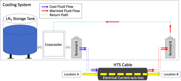
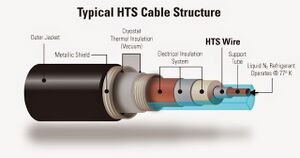
In general, there are three types of superconductors: low temperature superconductors, high temperature superconductors and room temperature superconductors. The Right-sided figure shows the typical depiction of high temperature superconducting cable, incorporating high temperature superconducting materials, which is designed to conduct electricity with zero resistance by using liquid nitrogen to cool the superconductors up to certain enough temperature(e.g., to 77k) and activate the superconductivity phenomenon. Compared with the traditional low temperature superconducting materials, which necessitate even lower temperatures, typically requiring liquid helium, high temperature superconducting cable can perform the superconductive state with relatively higher temperatures inside the cable. It means that the high temperature superconducting cable is advantageous regarding the cooling costs and the availability of coolants.
The system concept of the high temperature superconducting cable (including a cooling system) transporting electrical current without loss is as follows. Typically, High Temperature Superconducting (HTS) wires, consisting of superconducting materials, are placed in a pipe (cryostat thermal insulation) with a vacuum, which thermally isolates the superconductor from the remaining environment. Inside the pipe is the liquid nitrogen flow path. The technology requires special cable joints and specific cable termination for extreme temperature differences and a permanent cooling system for keeping the cryostat. Note: If room temperature superconductors that operate at atmospheric pressure are discovered in the future, the need for a cooling system can be eliminated. That is one of the ultimate technologies; however, they are still in the basic research stage.
Design Structure Matrix (DSM) Allocation
The 3SC-tree that we can extract from the DSM above shows us that the Superconducting Cable (3SC) is part of a larger system initiative on Superconducting Power Transmission (2SPT), and Superconducting Power Transmission is also part of a larger initiative on achieving Efficient Electric Power Supply (1EEPS).
As subsystem level of the Superconducting Power Transmission, other than Superconducting Cable, the following are required: Power Output Control (3POC), Power Generation (3PG), Power Substation (3PS) and Power Conversion (3PC).
Superconducting Cable requires the following key enabling technologies at the component level: Superconducting Wires (4SW), Cooling (4COL), Thermal Insulation (4TI), Electrical Insultation (4EI) and Magnet Field Insulation (4MFI). These five are the most common technology components to apply the phenomenon of superconductivity to the power transmission cable.
Roadmap Model using OPM
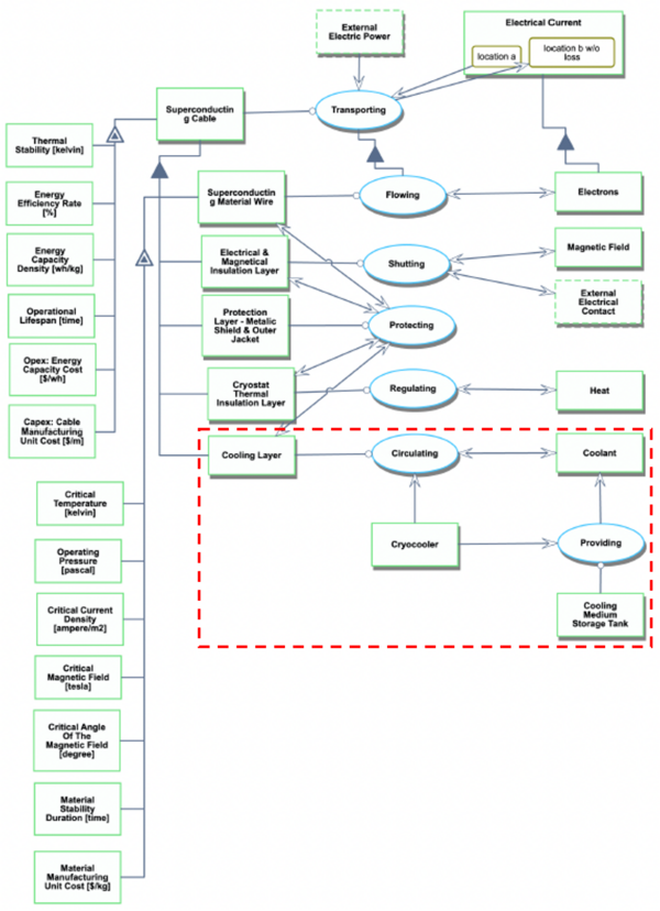
We provide an Object-Process-Diagram (OPD) of the 3SC roadmap in the figure below. This diagram captures the main object of the roadmap (Superconducting Cable), including subsystem decompositions such as superconducting material wire and cooling system, and characterizes the Figures of Merits (FOMs) as well as the main processes (transporting) and state changes (electrical current from location A to location B without loss). Note that for room-temperature superconducting cables, the area enclosed by the red dashed-line square can be deleted from the OPD because it does not require the cooling medium.
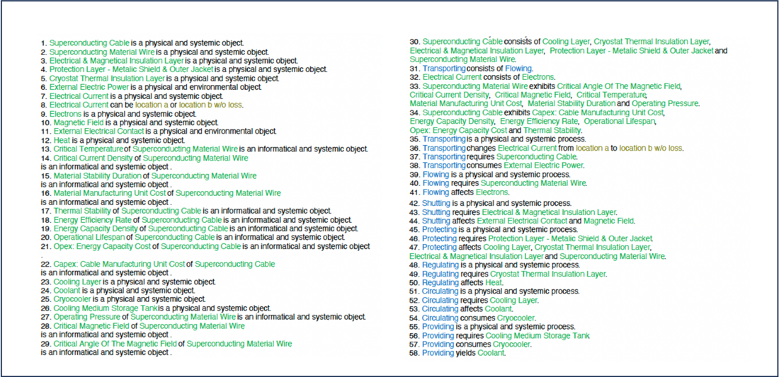
An Object-Process Language (OPL) of the roadmap scope, which corresponds with the above OPD, is shown as follows:
Figures of Merit
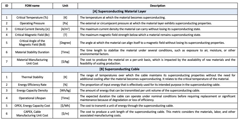
The table below shows a list of FOMs by which superconducting cable can be assessed. The FOMs are divided into two groups, compatible with the OPD. Group A shows the FOMs for the superconducting material layer, and Group B shows the FOMs for the superconducting cable, the technology itself we have chosen. To quantify how well a technology performs and how valuable the technology is for the users, it is indispensable to focus on the superconducting material layer, which is critical at the lower level of the system, as well as the cable.
The important FOM trends over time dFOM/dt as well as some of the key governing equations that underpin the technology are summarized as follows:
Critical Temperature and operating pressure
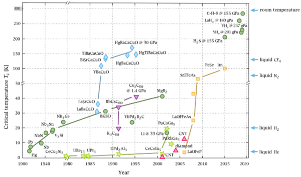
The critical temperature (Tc), the most prominent FOM, has evolved by following some stepping and rising trends. The journey of superconductors began with their discovery in 1911 by Heike Kamerlingh Onnes. Since then, the quest to elevate the critical temperature (Tc) has been relentless. Initially, the focus was on iron-based superconductors, represented by green dots in the following figure (It represents the historical trends of the critical temperature).
The then governing equation in superconductivity was assumed by BCS theory, a fundamental one based on the following equation:
A monumental shift occurred in 1986 with the emergence of high-temperature superconductors like LaBaCuO, symbolized by blue diamonds, which was beyond the BCS theory and its governing equation. While Nb-based superconductors had a Tc of 20-30K, the high-temperature variant YBCO soared beyond 100K, surpassing even the liquid nitrogen temperature (77K). This achievement held immense practical implications. The subsequent years saw the discovery of superconductors nearing room temperature, though their real-world application is constrained by the need for extremely high pressures, often exceeding 100GPa (i.e., The operating pressure is another FOM of the technology). At present, the critical temperature is found through simulations and experiments, not yet elucidated the governing equations. To summarize the trends, the critical temperature has risen by 280 Kelvin for 110 years since 1911, which means that the rate of critical temperature increase is 2.5 Kelvin per year.
Energy Efficiency Rate
The Energy Efficiency Rate follows the governing equation shown in Right, which means a higher rate indicates minimal energy losses during transmission. For superconducting cables, the efficiency should ideally be close to 100%, indicating nearly zero energy loss during transmission. While over the years, there has been a consistent effort to improve their performance by following the trends of decreasing loss, especially against challenges such as short circuit faults, the present efficiency is around 95% at best. The rate has improved by 20% for 70 years, which means that the increase in the energy efficiency rate is about 0.3% per year(Calculated based on the source: https://www.tepco.co.jp/corporateinfo/illustrated/electricity-supply/transmission-distribution-loss-j.html).
Alignment with Company Strategic Drivers
The following table shows our strategic drivers and the alignment of those drivers with this roadmap. As the table shows, the roadmap for superconducting cable technology is insufficient by itself to enable other superconducting application technologies, which lead the research and development of superconducting material itself. That is, other applications could develop our roadmap, adding different perspectives about the strategic drivers for the technology.
| # | Strategic Driver | Alignment and Targets |
|---|---|---|
| 1 | To develop a long enough superconducting material layer with mechanical strength to maintain its superconducting properties at atmospheric pressure when subjected to bending, twisting, or other physical forces by 2025. | The 3SC technology roadmap will target to make the superconducting material layer at least 1 mile (1.6km), which can transmit more than 10kA electricity at 650kV by DC power cables.
This strategic driver is aligned but not fully covered with the technology roadmap for the superconducting ”cable”, because it depends on the kinds of superconducting material applications. |
| 2 | To develop an affordable cooling system for insulating the heat of superconducting cables that will launch a profitable marketplace where we have a distinct advantage in the superconducting cable market instead of the regular electrical cable market by 2030. | The 3SC technology roadmap will develop and test the cooling system, leading to the reduction of the total operating cost compared to the regular electrical cables by 40% in total system.
This strategic driver is aligned with the technology roadmap as this target corresponds with FOM #B5. |
| 3 | To develop a superconducting cable with joints and quenching subsystem that can be safely connected with electric power substations and factories, where the technology will replace existing regular electrical cables by 2040. | The 3SC technology roadmap will help to develop the applicable quenching subsystem by detecting the predictors of quenching enough before the system’s failures and stopping the electricity flows.
This strategic driver is partially aligned with the 3SC roadmap, though different breakthroughs about quenching subsystems could impact the roadmap. |
| 4 | To develop a room-temperature superconducting material layer that can be operated at atmospheric pressure to remove the cooling system, where all existing copper cables could be replaced by 2050. | The 3SC technology roadmap could scope the discovery of the room-temperature superconducting material layer, but such materials (that are regarded as disruptive innovation) have not been discovered at all as of 2023.
This strategic driver is aligned with the 3SC roadmap as this target corresponds with FOM #A1~A7. |
Positioning of Company vs. Competition
In the competitive landscape, the “company” faces rivalry from several key players: Ampa City (Germany), Ishikari (Japan), Saint Petersburg (Russia), HYDRA (US), and Shingal (South Korea). Given that some projects are financed or managed by government or national institutes*, the superconducting cable is regarded as a technology that includes some high-level technical challenges and/or implies difficulties in profitability. Also, the technology, highly related to the electricity system flexibility, is expected to contribute to developing high-capacity transmission networks to meet the national/regional big goals about the energy balance. Therefore, for overviewing the competitive environment, it is necessary not only to compare the technological properties but also to understand each project’s background.
(*Ampa City: Funded by the German Government, Ministry of Economics and Technology, Ishikari: Sponsored by the National Institute of Advanced Industrial Science and Technology, Japan, HYDRA: Operated by Oak Ridge National Laboratory, the Department of Energy, US)
The following table summarizes the significant parameters to explain the technology development in each project. Based on the coolant, consisting of the most costly subsystem in the technology, all projects adopt the high-temperature superconducting material (HTS) like BSCCO (Bismuth Strontium Calcium Copper Oxide) and YBCO (Yttrium Barium Copper Oxide) with liquid nitrogen as a cooling medium. The cable types, AC (alternating current) or DC (direct current) are different depending on each project goal and utility scenario, as described above. In general, each project has its target about the longer length of the cable, which can transmit electricity with high operating voltage and ampere with specific stability, scoping their future applications. The longer the cable is, the more complex the cable’s stability is.
Reference
1: Ampa City
- M. Stemmle, F. Merschel, M. Noe, and A. Hobl, “Ampacity project - worldwide first superconducting cable and fault current limiter installation in a German city center,” in 22nd International Conference and Exhibition on Electricity Distribution (CIRED 2013), Institution of Engineering and Technology, 2013, pp. 0742–0742. doi: 10.1049/cp.2013.0905. (http://cired.net/publications/cired2015/papers/CIRED2015_0678_final.pdf)
- https://www.tdworld.com/overhead-distribution/article/20964180/the-ampacity-project
2: Ishikari
- S. Yamaguchi et al., “Construction and 1st Experiment of the 500-meter and 1000-meter DC Superconducting Power Cable in Ishikari,” in Physics Procedia, Elsevier B.V., 2016, pp. 182–186. doi: 10.1016/j.phpro.2016.04.046. (https://www.sciencedirect.com/science/article/pii/S1875389216300463)
- https://ieeexplore.ieee.org/document/9366972
- https://www.city.ishikari.hokkaido.jp/soshiki/kankyo/20401.html
3: Saint Petersburg
- V. Sytnikov, A. Kashcheev, M. Dubinin, V. Karpov, and T. Ryabin, “Test Results of the Full-Scale HTS Transmission Cable Line (2.4 Km) for the St. Petersburg Project,” IEEE Transactions on Applied Superconductivity, vol. 31, no. 5, Aug. 2021, doi: 10.1109/TASC.2021.3063067. (https://ieeexplore.ieee.org/stamp/stamp.jsp?tp=&arnumber=9366972)
- https://globalenergyprize.org/en/2020/04/29/saint-petersburg-will-receive-electricity-trough-the-worlds-longest-superconductor-line/#:~:text=The%20HTS%20CL%20is%20based,certain%20temperatures%2065%2D80%20K.
4: HYDRA
5: Shingal
- C. Lee et al., “Progress of the first commercial project of higherature superconducting cables by KEPCO in Korea,” Supercond Sci Technol, vol. 33, no. 4, 2020, doi: 10.1088/1361-6668/ab6ec3. (https://iopscience.iop.org/article/10.1088/1361-6668/ab6ec3/meta#:~:text=Korea%20Electric%20Power%20Corporation%20(KEPCO,operations%20are%20ready%20to%20start)
Technical Model
TBD
Financial Model
TBD
List of R&D Projects and Prototypes
TBD
Key Publications, Presentations and Patents
Our review of patents and academic papers aims to facilitate the pragmatic implementation of superconducting cables, by identifying the three technological domains as follows:
- 1. Enhancement of Critical Current Density in Superconducting Materials under High Magnetic Fields
- 2. Techniques for Lengthening and Cooling Superconducting Cables for Practical Use
- 3. Technology for Superconducting Cable Failure Modes
1. Enhancement of Critical Current Density in Superconducting Materials under High Magnetic Fields
- Key publication
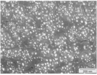
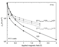
Superconducting materials experience degradation under high magnetic fields due to the generation of self-magnetic fields and exposure to external magnetic fields. T. Haugan's research revealed that introducing impurities to superconductors can mitigate this degradation. In the YBCO superconducting material, as visualized in the SEM image (upper figure), bromine (Br) impurities ranging from nanometers to tens of nanometers are present. The authors modified the typical YBCO composition, resulting in enhanced critical current densities under magnetic fields (lower figure).
Source: T. Haugan, P. N. Barnes, R. Wheeler, F. Meisenkothen, and M. Sumption, “Addition of nanoparticle dispersions to enhance flux pinning of the YBa2Cu3O7-x superconductor,” Nature, vol. 430, no. 7002, pp. 867–870, Aug. 2004, doi: 10.1038/nature02792. (https://www.nature.com/articles/nature02792)
- Key patent
Sumitomo Electric Industries patented a method (PCT/JP2017/039310) to enhance critical current density by introducing bromine (Br) to YBCO superconducting materials.
Source: T. MOTOKI, J. SHIMOYAMA, G. HONDA, T. NAGAISHI, Sumitomo Electric Industries, Ltd., Osaka-shi, Osaka (JP), Aug. 12, 2019, “OXIDE SUPERCONDUCTING THIN FILM MATERIAL, OXIDE SUPERCONDUCTING THIN FILM WIRE, AND METHOD FOR MANUFACTURING OXIDE SUPERCONDUCTING THIN FILM”, PCT/JP2017/039310
2. Techniques for Lengthening and Cooling Superconducting Cables for Practical Use
- Key publication
For superconducting cables to be practical, addressing the challenge of lengthening is vital. Factory-shipped superconducting cables have inherent length limitations due to their diameter and manufacturing constraints. S. Mukoyama's experiment showcased the potential of a 50-meter high-temperature superconducting cable, emphasizing adjustments in impedance to minimize AC transmission losses.
Source: S. Mukoyama et al., “50-m long HTS conductor for power cable,” IEEE Transactions on Applied Superconductivity, vol. 7, no. 2, pp. 1069–1072, Jun. 1997, doi: 10.1109/77.614709. (https://ieeexplore.ieee.org/document/614709)
- Key patent
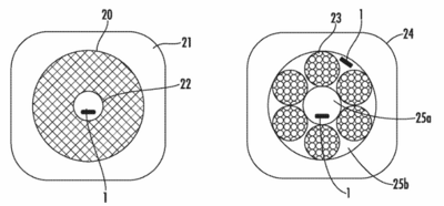
R. Fukuda's patent (H01B 12/16 (2013.01); H02G I/081(2013.01); H02G 15/34 (2013.01)) shows the invention of the cooling approach for superconducting cables. Instead of the traditional design where the core is encased within a coolant flow path, his design strategically places an external coolant channel separate from the core. This innovation not only allows for the creation of longer superconducting cores but also optimizes cooling efficiency. By ensuring uniform and effective temperature maintenance across the cable, especially for extended lengths, Fukuda's approach provides a balanced and pragmatic solution that addresses both design flexibility and operational stability in superconducting cables.
Source: R. FUKUDA, Feb. 21, 2014, SUPERCONDUCTING CABLE,SUPERCONDUCTING CABLE LINE,METHOD OF INSTALLING SUPERCONDUCTING CABLE, AND METHOD OF OPERATING SUPERCONDUCTING CABLE LINE, H01B 12/16 (2013.01); H02G I/081(2013.01); H02G 15/34 (2013.01)
3. Technology for Superconducting Cable Failure Modes
- Key publication
The "quench" phenomenon, a sudden transition from a superconducting state to a non-superconducting state, poses significant risks to the whole system's safety. Several factors, such as heat or material defects, can trigger quench. Yawei Wang's research using high-temperature superconducting REBCO thin films provides insights into predicting quench events and understanding their causes.
Source: Y. Wang, J. Zheng, Z. Zhu, M. Zhang, and W. Yuan, “Quench behavior of high-temperature superconductor (RE)Ba2Cu3Ox CORC cable,” J Phys D Appl Phys, vol. 52, no. 34, Jun. 2019, doi: 10.1088/1361-6463/ab1e2c. (https://iopscience.iop.org/article/10.1088/1361-6463/ab1e2c)
- Key patent
M. Takayasu's patent (G01K 13/006) proposes quench detection using strain measurements from multiple pressure sensors, offering a potential solution to this challenge, as shown in the right figure.
Source: M. TAKAYASU, Oct. 20 , 2020, “DISTRIBUTED-SENSOR QUENCH DETECTION METHOD FOR SUPERCONDUCTING DEVICES”, GO1K 13/006 (2013.01) ; GOIK 5/28 (2013.01) ; GOIK 5/04 (2013.01)
Technology Strategy Statement
TBD
References
TBD
