Satellite Autonomous Systems
Satellite Autonomous Systems for Rendezvous and Proximity Operations
Roadmap Overview

There is a need for satellites designed to perform a wide range of tasks in space without constant human intervention, including navigation, data collection, decision-making, rendezvous, proximity operations, docking, debris disposal, and servicing. We present a strategic plan supported by a technological pathway for the development and deployment of satellites capable of operating autonomously in space, focusing in on autonomous systems for Rendezvous and Proximity Operations (RPO).
Autonomous satellites will be equipped with advanced onboard systems that allow them to navigate and adjust their orbits, avoiding collisions with other space objects or debris, enhancing the efficacy of space missions. Advanced onboard processing is needed for real time decision making that allows for responses to dynamic situations and course correction, particularly in RPO. The ability to communicate and make decisions autonomously with information shared between satellites is valuable for many mission types including In-Space Servicing, Assembly, and Manufacturing (ISAM), Active Debris Removal (ADR), and constellations of satellites working together in formation flight.
DSM Allocation


Roadmap Model using OPM
Figures of Merit (FOM)
Autonomous systems for Rendezvous and Proximity Operations (RPO) can be utilized for a number of spacecraft missions, including inspection, capture, docking, servicing, formation flight, etc. Given this variety, it is difficult to standardize FOMs among all mission types. Some proposed FOMs are identified in the table below.

Proposed Safety-Related FOMS
A survey of missions which included elements of RPO published in 2018 and performed by the University of Southern California’s (USC) Space Engineering Research Center (SERC) in association with the Consortium for Execution of Rendezvous and Servicing Operations (CONFERS) sought to identify potential attributes for comparison in order to define safe standards for RPO [1]. The survey found that there were only a few comparable attributes with no discernable pattern other than proposed ‘safety nets’ around targets during approach, which could vary widely among mission types. However, there was agreement that these systems should perform accurately while applying the principle of ‘do not harm’ to the space environment by preventing debris creating collisions. The SERC therefore proposed three metrics to address safety within the final approach of RPO: Contact Velocity, Remote Influence, and Control Accuracy. These metrics are unitless ratios and therefore independent of scale and are assumed to be applied to two spacecraft (a chaser and target); so they are not necessarily applicable to RPO with pieces of debris.
Contact Velocity is based on the practice of maintaining a relative velocity to the target such that if no braking maneuver is executed, the collision of the spacecraft will not result in separable debris from either. It is defined as the ratio of the projected velocity of final approach over the maximum permissible velocity to prevent debris creation, accounting for the stress and momentum of the spacecraft. A CV < 1 is at low risk of critical damage while a CV > 1 is at high risk.
Remote Influence is based on the practice of maintaining a distance between the spacecraft and orientation such that forces from the chaser spacecraft (like thruster plume) don’t exert unintended torque on the target. It is defined as the ratio of the projected angular velocity from plume impingement to the maximum permissible angular velocity. An RI < 1 is not at risk of loss of target control while RI > 1 is at risk.
Control Accuracy is mainly related to mission types where connection between spacecraft is intended and is based on the practice of maintaining control of the chaser such that the worst-case offset error does not exceed the Effective Capture Distance (ECD) of the chaser’s contact/capture mechanism. It is defined as the ratio of the Maximum Capture Offset (MCO) to the ECD. A CA < 1 is at low risk of not connecting while CA > 1 is at high risk.
Using the results from the survey, the SERC calculated these metrics for three example RPO missions shown in the table below [2]. Contact Velocity was calculated for three additional missions in a subsequent paper (Note: RESTORE-L is now the OSAM-1 mission).
When graphed, these FOMs exhibit interesting characteristics related to technological development. The theoretical limit for each of them is 0 since this when no potential inadvertent force or contact would occur. Looking further at the Control Accuracy FOM, this does seem to exhibit a potential part of an inverted S-Curve, though there are too few data points to confirm. Based on this, however, we may estimate that the technology is currently in the slowing to stagnation phase of the technology development. We can also perhaps see a partial of an inverted S-Curve when looking at the Contact Velocity FOM, though it is thrown off by the newer missions. This could be a result though of the different risk tolerances of the mission types (human carrying vs. not) that lead to certain design choices which influence the FOM.


When Contact Velocity vs. Control Accuracy is graphed, one can see a possible Pareto Shift Model, with each newer system shifting lower.

In theory, there is a physical limit to the positional accuracy for autonomous systems using optical sensors, and this limit is mainly determined by the laws of physics, particularly the diffraction limit. The diffraction limit defines the smallest resolvable details or features that an optical or radio system can distinguish. This limit is a fundamental constraint on all optical systems, including space cameras, telescopes, and sensors.
The diffraction limit, which defines the minimum resolvable angle (θ) for a circular aperture, is given by the formula:

To evaluate the theoretical limit to remotely sensed location (which affects our FOM of accuracy), let's assume we have a radar system operating at a wavelength of 1 centimeter (0.01 meters) with an antenna size of 5 meters. If we are observing an object 10,000 kilometers away using a radar system with a specific wavelength and antenna size, we can use this formula to calculate the angular resolution. Using the formula:

This translates to an positional accuracy within .00244rad*10000km= 24.4km
Alignment with Company Strategic Drivers
Two strategic drivers necessary for producing an effective and trustworthy satellite autonomous system for RPO are detailed below.
While Strategic Driver #2 is well on it's way of being achieved, with some examples already of missions with at least one of the proposed safety-related FOMs < 0.01, Strategic Driver #1 has longer to go in developing an autonomous system for RPO completely free of real-time human interaction.
Positioning of Company vs. Competition
There are many companies that may equip their satellites with an autonomous system for RPO, some of which are detailed in the table below.

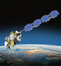
(Northrop Grumman Military ComSat)
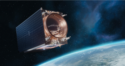
(Lockheed Martin 400)
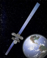
(Boeing 702)
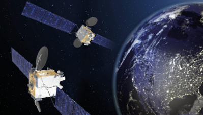
(Thales SES-22)
(Maxar Worldview)


Technical Model
Contact Velocity
The safety of autonomous systems for RPO can be modeled and measured in a variety of ways. One potential model and metric for this is that of Contact Velocity. Contact Velocity is based on the practice of maintaining a relative velocity to the target such that if no braking maneuver is executed, the collision of the chaser spacecraft with the target will not result in separable debris from either. As seen in the equation below, it is defined as the ratio of the projected velocity of final approach over the maximum permissible velocity to prevent debris creation. A CV < 1 is at low risk of critical damage while a CV > 1 is at high risk.
This maximum permissible approach velocity can be found by modeling the characteristics of the chaser and target as described below, taking into account the mass of both spacecraft, the material properties of the target, potential impact area of the chaser, estimated impulse time, a Coefficient of Restitution (CR) based on material malleability, and a Factor of Safety (FS).
The normalized tornado chart for this sensitivity analysis is shown below. Three of the variables are positive and two are negative. This makes sense because as the impact pressure the spacecraft can withstand and the area over which it occurs and the time goes up, the greater velocity the impact can be at. Whereas, as the spacecraft get closer in size to each other (the mass ratio goes up) and the CR goes up, meaning the material is more rigid, the max velocity it could take goes down. As shown in the chart, the CR is less sensitive than the rest of the variables.

Positional Accuracy
The potential positional accuracy of an autonomous system for RPO can be modeled using the diffraction limit, which defines the minimum resolvable angle for a circular aperture with the wavelength of light and the diameter of the aperture. This times the distance between objects gives the positional accuracy.
A sensitivity analysis was performed for this FOM in the same manner as discussed above. The normalized tornado chart is shown below. No variable is shown to be more sensitive than another.

Key Publications and Patents
Publications
Historically in the US, RPO has been completed manually by astronauts with the assistance of technology. In the earliest days, astronauts utilized line-of-sight guidance techniques to complete RPO maneuvers with radar ranging. This was studied in Edwin ‘Buzz’ Aldrin’s 1963 MIT Dissertation, “Line-of-Sight Guidance Techniques for Manned Orbital Rendezvous” [4]. His Dissertation explored the inertial rotation of line-of-sight through rendezvous trajectories with only angular motion tracking information of a target spacecraft known without ranging. Buzz applied the technique in simulation of the Gemini rendezvous mission as well. He also noted that the “important question” of autonomy “concerning the proper allocation of the human resources to either direct participation controlling or a mere monitoring role in the overall mission is as yet not completely settled.”
In “Navigating the Road to Autonomous Orbital Rendezvous” (2007), David Woffinden and David Geller of Utah State University explore the birth and progress of autonomous RPO [5]. It can be seen that essentially from the start, the US and Russian space programs took two different approaches to orbital rendezvous operations. The US focused on manned operations that reduced complexity and allowed for flexibility, but made each mission unique and required intensive training. The Russians, on the other hand, focused on more automated operations with astronauts in a monitoring and override role. This increased development time and cost initially, but standardized systems between missions and reduced recurring engineering work. The paper argues that the Russian’s focus on automated RPO was likely a consequence of the military’s influence in their space program and push for automatization in order to reduce redesign between manned and reconnaissance missions. The differences between national approaches are seen in the subsequent design and legacy of RPO systems as outlined by Woffinden and Geller. The paper also explores the idea that the autonomous RPO systems of the future must meet new demands that are now possible due to the development of technology and techniques across the past half century of space exploration and orbital rendezvous operations.
Patents
Patents were found through the US Patent and Trademark Office’s online Patent Public Search tool. A search was performed with combinations of key terms using the AND operator: satellite/spacecraft/space+rendezvous, satellite/spacecraft/space+autonomous/autonomy, satellite/spacecraft/space+proximity, satellite/spacecraft/space+docking. Results were categorized according to five areas: Satellite Autonomy, Satellite Navigation, Satellite Maneuvering, Rendezvous, and Docking/Capture. The CPC classification is 244 for Aeronautics and Astronautics, 701 for Vehicles, Navigation, and Relative Location, and 382 for Image Analysis.
US Patent 5,951,609 “Method and System for Autonomous Spacecraft Control”, dated Sep. 14th, 1999 by Hanson et. al. of TRW Inc., outlines a system for autonomous spacecraft control by managing onboard systems, monitoring performance with optimization, and fault detection with adaptive fault recovery [6]. A proposed “mission manager module” is utilized to analyze incoming mission objective commands and verify resourcing. These mission objective commands are then translated by a “command processor” into lower level command sequences for the subsystems to perform.

US Patent 5,734,736 “Autonomous Rendezvous and Docking System and Method Therefor”, dated Mar. 31st, 1998 by Palmer et. al. of TRW Inc., characterizes a system for performing autonomous rendezvous and docking using reflective targets to determine relative position between a chaser and target spacecraft [7]. A reflective target is attached to the target spacecraft which reflects radiation to a sensor, receiving radiation of “a first in band wavelength” and illuminating the target with “a second out of band wavelength”. The sensor system can distinguish between the two and produce a difference image which can discriminate the reflective target position from spurious light based on known target “intensity, size, shape, and location”. This can then be utilized to produce a state vector of the target spacecraft relative to the chaser.
US Patent 2002/0035419 A1 “Autonomous Navigation, Guidance and Control using LDRI”, dated Mar. 21st, 2002 by Ching-Fang Lin, describes a process for docking and formation flight utilizing a Laser Dynamic Range Imager (LDRI) [8]. The proposed system eliminates the need for unique targets on spacecraft, “which are highly dependent on illumination and orientation.” The LDRI avoids the illumination problem by using a continuous wave laser radar. Range is found through the phase shift between incident and reflected laser beams coming from each pixel. The target’s motion can then be calculated using the light intensity and range images. The relative position and attitude error is then used to produce control commands for rendezvous. A similar system was used by the US Space Shuttle program.

Financial Model (TBD)
R&D Portfolio (TBD)
Technology Strategy Statement (TBD)
Roadmap Maturity Assessment (TBD)
References
[1] https://www.isi.edu/sites/default/files/centers/serc/CONFERS_IAC_Paper_PUBLISH.PDF [2] https://www.isi.edu/sites/default/files/users/barnhart/INITIAL%20SAFETY%20POSTURE%20INVESTIGATIONS%20FOR%20EARTH%20REGIME%20RENDEZVOUS%20AND%20PROXIMITY%20OPERATIONS%20-%20IAASS%202019.pdf [3] https://pressbooks.online.ucf.edu/phy2053bc/chapter/limits-of-resolution-the-rayleigh-criterion/ [4] https://dspace.mit.edu/handle/1721.1/12652 [5] https://arc.aiaa.org/doi/pdf/10.2514/1.30734?casa_token=A5dxnyeh6v4AAAAA:5ad2z08Y35KCEuGKZj9tKGc_X_FqBx4EuofPcEHcaztVvbVrCP9G1A7x6Za06c3HW0XDaru59EFcOw [6] https://image-ppubs.uspto.gov/dirsearch-public/print/downloadPdf/5951609 [7] https://image-ppubs.uspto.gov/dirsearch-public/print/downloadPdf/5734736 [8] https://image-ppubs.uspto.gov/dirsearch-public/print/downloadPdf/20020035419