Energy Storage via Battery
Technology Roadmap Sections and Deliverables
The first point is that each technology roadmap should have a clear and unique identifier:
- 2SEA - Solar Electric Aircraft
This indicates that we are dealing with a “level 2” roadmap at the product level (see Fig. 8-5), where “level 1” would indicate a market level roadmap and “level 3” or “level 4” would indicate an individual technology roadmap.
Roadmap Overview
The working principle and architecture of an electrical battery are depicted in the below.
An electrical battery can store and use energy by chemical reaction. It is composed of an anode (-), a cathode (+), the electrolyte, and separator. The chemical reaction is a redox reaction caused by an electrical difference between the anode and the cathode. That is, electrons are expelled from the anode to the cathode via an external circuit and metal ion in the electrolyte receives the electrons on the cathode. This redox reaction lasts until
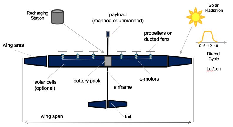
two electrodes (anode and cathode) built from light-weight materials such as wood or carbon-fiber reinforced polymers (CFRP) and harvest solar energy through the photoelectric effect by bonding thin film solar cells to the surface of the main wings, and potentially the fuselage and empennage as well. The electrical energy harvested during the day is then stored in on-board chemical batteries (e.g. Lithium-Ion, Lithium-Sulfur etc…) and used for propelling the aircraft at all times, including at night. For the system to work there needs to be an overproduction of energy during the day, so that the aircraft can use the stored energy to stay aloft at night. The flight altitude of about 60,000-70,000 feet is critical to stay above the clouds and not to interfere with commercial air traffic. Depending on the length of day, i.e. the diurnal cycle which determines the number of sunshine hours per day, which itself depends on the latitude and time-of-year (seasonality) the problem is easier or harder. The reference case in the technology roadmap is an equatorial mission (latitude = zero) with 12 hours of day and 12 hours of night.
Solar-electric aircraft are built from light-weight materials such as wood or carbon-fiber reinforced polymers (CFRP) and harvest solar energy through the photoelectric effect by bonding thin film solar cells to the surface of the main wings, and potentially the fuselage and empennage as well. The electrical energy harvested during the day is then stored in on-board chemical batteries (e.g. Lithium-Ion, Lithium-Sulfur etc…) and used for propelling the aircraft at all times, including at night. For the system to work there needs to be an overproduction of energy during the day, so that the aircraft can use the stored energy to stay aloft at night. The flight altitude of about 60,000-70,000 feet is critical to stay above the clouds and not to interfere with commercial air traffic. Depending on the length of day, i.e. the diurnal cycle which determines the number of sunshine hours per day, which itself depends on the latitude and time-of-year (seasonality) the problem is easier or harder. The reference case in the technology roadmap is an equatorial mission (latitude = zero) with 12 hours of day and 12 hours of night.
Design Structure Matrix (DSM) Allocation
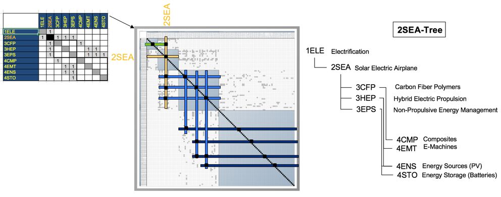
The 2-SEA tree that we can extract from the DSM above shows us that the Solar-Electric Aircraft (2SEA) is part of a larger company-wide initiative on electrification of flight (1ELE), and that it requires the following key enabling technologies at the subsystem level: 3CFP Carbon Fiber Polymers, 3HEP Hybrid Electric Propulsion and 3EPS Non-Propulsive Energy Management (e.g. this includes the management of the charge-discharge cycle of the batteries during the day-night cycle). In turn these require enabling technologies at level 4, the technology component level: 4CMP components made from CFRP (spars, wing box, fairings …), 4EMT electric machines (motors and generators), 4ENS energy sources (such as thin film photovoltaics bonded to flight surfaces) and 4STO (energy storage in the form of lithium-type batteries).
Roadmap Model using OPM
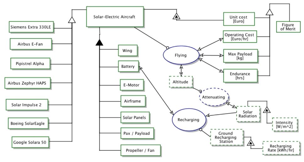
We provide an Object-Process-Diagram (OPD) of the 2SEA roadmap in the figure below. This diagram captures the main object of the roadmap (Solar-Electric Aircraft), its various instances including main competitors, its decomposition into subsystems (wing, battery, e-motor …), its characterization by Figures of Merit (FOMs) as well as the main processes (Flying, Recharging).
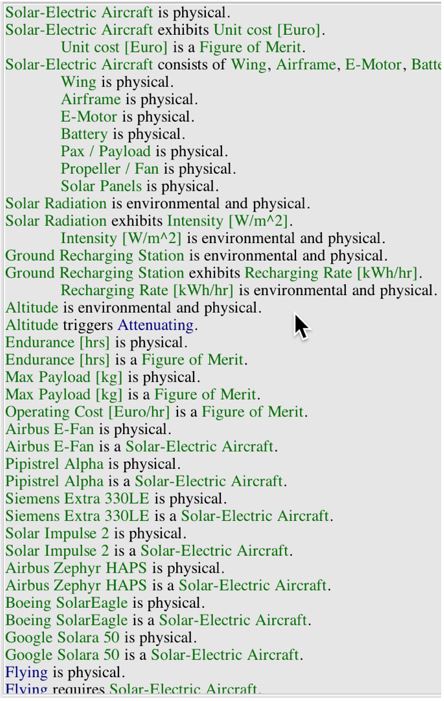
An Object-Process-Language (OPL) description of the roadmap scope is auto-generated and given below. It reflects the same content as the previous figure, but in a formal natural language.
Figures of Merit
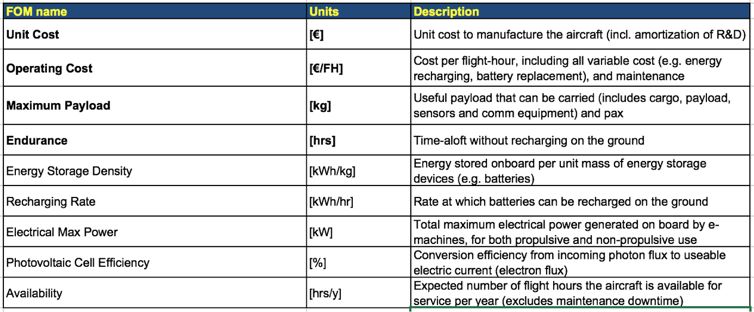
The table below show a list of FOMs by which solar electric aircraft can be assessed. The first four (shown in bold) are used to assess the aircraft itself. They are very similar to the FOMs that are used to compare traditional aircraft which are propelled by fossil fuels, the big difference being that 2SEA is essentially emissions free during flight operations. The other rows represent subordinated FOMs which impact the performance and cost of solar electric aircraft but are provided as outputs (primary FOMs) from lower level roadmaps at level 3 or level 4, see the DSM above.
Besides defining what the FOMs are, this section of the roadmap should also contain the FOM trends over time dFOM/dt as well as some of the key governing equations that underpin the technology. These governing equations can be derived from physics (or chemistry, biology ..) or they can be empirically derived from a multivariate regression model. The table below shows an example of a key governing equation governing (solar-) electric aircraft.
