Optical Payload for Space Situational Awareness in Geosynchronous Orbit
Technology Roadmap Sections and Deliverables
This is a technology roadmap for:
- 3HSSA - Space Situational Awareness for the Hungarian Space Office
Roadmap Overview
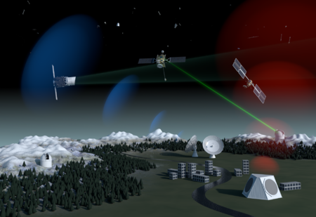
Artist's impression of various SSA systems comprising a full SSA architecture.<ref>“Space Surveillance and Tracking - SST Segment.” Accessed October 1, 2020. https://www.esa.int/Safety_Security/Space_Surveillance_and_Tracking_-_SST_Segment. </ref>
Our technology roadmap concept—a low-cost space situational awareness sensor that could be integrated into a geostationary (GEO) satellite bus—was motivated by one particular research question:
How can an emerging space actor contribute to space situational awareness in the geosynchronous region by launching just one satellite to GEO?
Space situational awareness (SSA)—detecting, identifying, and tracking resident space objects (RSOs) as they orbit the Earth—requires observing many RSOs, using the measurements deduced from those observations to determine the orbit of each object, and then using those determined orbits to identify objects again in the future, while further improving their orbital parameters. Comprehensive SSA results in knowing where all RSOs of some minimum size are at a given time and where they’re going, which results in a reasonably accurate assessment of the likelihood of collision between two RSOs. The collision of two satellites typically results in catastrophic damage to both RSOs involved and the creation of thousands of pieces of space debris, uniformly unfavorable results for all space actors in the orbital regime in which the collision occurred.
SSA systems generate RSO observations using a variety of sensors: including ground- and space-based optical telescopes and radar systems. SSA in GEO, specifically, has historically been pursued using optical, ground-based telescopes, as part of broader systems maintained by the space actors that have contributed the most number of RSOs to the near-Earth space environment: the United States and Russia. Since SSA is critical to maintaining a sustainable GEO environment, improving SSA in GEO is the interest of all space actors, even those in their earliest stages.
A relatively nascent space actor—one in the early stages of planning its first GEO launch—may not find it feasible to develop a new ground-based optical telescope to contribute to global space situational awareness. They could, however, contribute excellent SSA observations for the sliver of the GEO belt that they intend to occupy with their satellite upon successful launch. The new space actor could plan to add a small, optical sensor to its GEO satellite designed to monitor the satellite’s vicinity during its operational lifetime and report its observations either to the public or an international space object catalog.
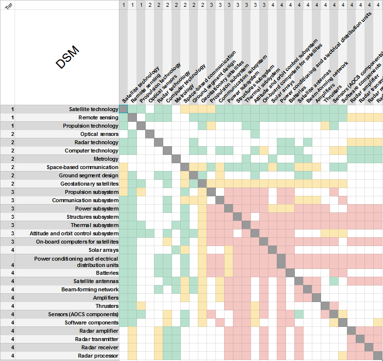
Design Structure Matrix (DSM) Allocation
The detailed DSM shows connections between the various technologies comprising the radar-based SSA (marked with green), as well as hierarchical relationships between technologies and objects (yellow), and physical relationships between components or subsystems (red).
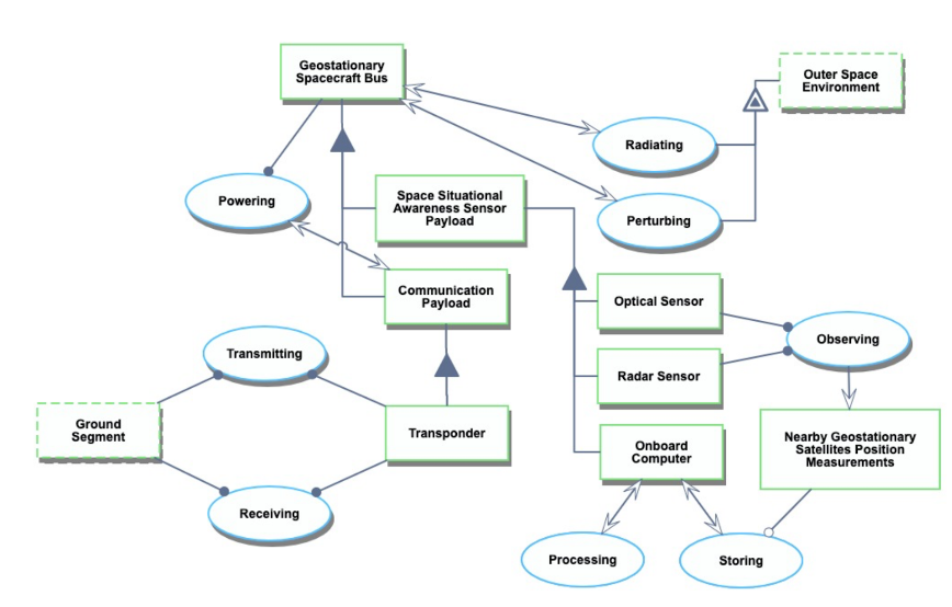
Roadmap Model using OPM
The Object-Process-Diagram (OPD) of a space-based SST-system flown on a GEO satellite is shown below.
Figures of Merit
Although there are standard Figures of Merit (FOMs) for optical sensors and radar systems in general, such as objective lens aperture [m] and signal-to-noise ratio, this specific technology—detecting nearby satellites in GEO—could be better measured by others. The table below describes several of these potential FOMs in greater detail, including their appropriate units.
| Figure of Merit | Units | Description |
|---|---|---|
| Spatial resolution at GEO | m | The physical distance that corresponds to one pixel of an optical image for GEO object observations; that is, the minimum separation distance between objects in GEO such that the sensor can detect two unique objects |
| Unit cost | $ | The cost of producing one on-orbit SSA sensor that could be integrated into a GEO satellite bus |
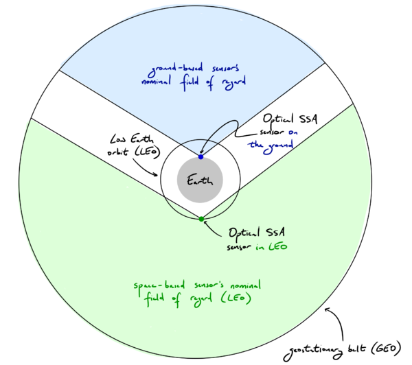
| Nominal GEO Field of Regard | # of orbital slots in view | The portion of the geostationary belt that the sensor could possibly observe (i.e. the GEO region, measured number of orbital slots) that aren't blocked by the Earth or its atmosphere from the perspective of the sensor); see Figure 4 |
| Minimum object size for detection | cm | The smallest object that the sensor could detect at GEO; directly related to spatial resolution |
| Exposure time | s | How long the space object must be observed before a measurement is taken |
| Readout time | s | How long it takes the on-board computer to report a detected satellite |
| CCD resolution | px | The number of pixels in each image created by the sensor |
| Field of view | sq. degrees | The angular size of the sensor's instantaneous field of view; not to be confused with the field of regard (the field of regard is limited by masking effects, the field of view is limited by telescope properties such as aperture and focal length) |
| Number of sensors required for full coverage | # | How many sensors are required to observe the entire geostationary belt instantaneously |
| Latency | s | The delay between when a nearby satellite is detected and when that information is communicated to the ground segment |
Let’s consider two FOMs from the table above in greater detail.
The nominal GEO field of regard, measured in number of orbital slots, describes the portion of the geostationary belt that the sensor could possibly observe from its vantage point. The top of Figure 4 shows the nominal field of regard for a ground-based optical SSA sensor and a space-based optical SSA sensor placed in equatorial LEO. Due to masking limitations (a masking angle of roughly 30 degrees is shown for illustrative purposes), a ground-based optical SSA sensor can only observe a minority of the 3,600 orbital slots in GEO. Due to the nature of the geostationary belt—in which each orbital slot’s position stays fixed relative to the Earth’s surface—a ground-based optical SSA sensor observes the same orbital slots over time. Although a space-based optical SSA sensor placed in LEO can observe a greater portion of the GEO belt, more than half of it, it too is limited due to masking constraints from the Earth and its atmosphere. Unlike a ground-based sensor, a LEO-based sensor observes different orbital slots over time, since their positions are not fixed with respect to the LEO sensor’s inertial reference frame. The bottom of Figure 4 shows the nominal field of regard for a space-based optical SSA sensor placed in GEO. Although an SSA sensor in GEO can observe a much greater fraction of the 3,600 orbital slots, it observes the GEO belt at vastly different distances, ranging from 0 m to nearly twice the geostationary radius. To account for the distance between the sensor and the satellites it’s observing, let’s consider the spatial resolution, a different figure of merit.
References
<references />


