Spacesuit Helmet Roadmap
¶ Spacesuit Helmet
¶ 1. Roadmap Overview
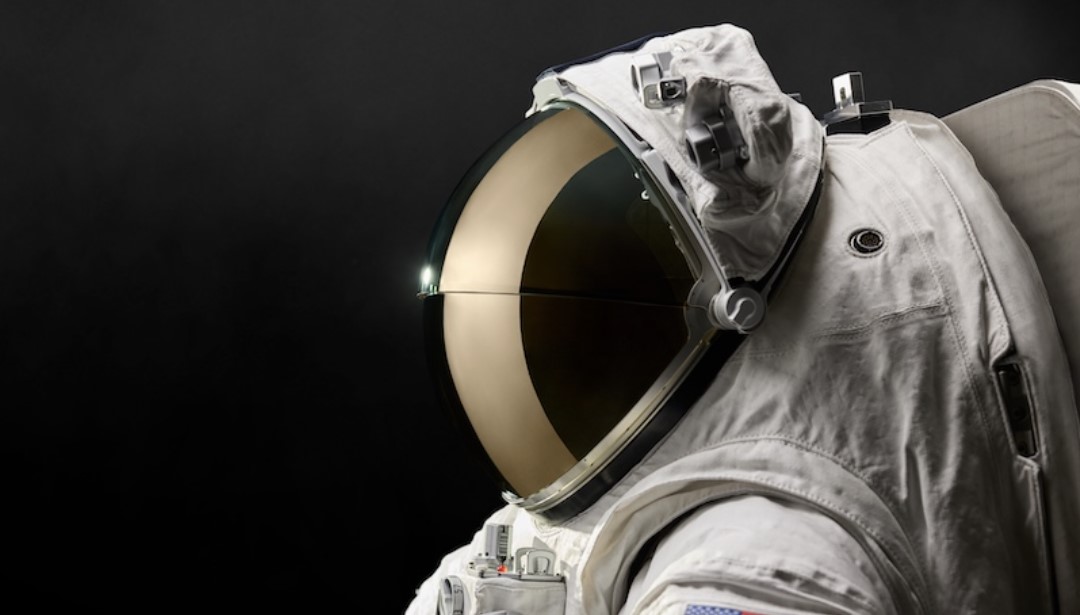
Spacesuit helmet designs were based on and adapted from high-altitude pressure suits developed since the 1930s. To meet the required protection from the harsh environment of outer space, the helmet has a critical role in providing shielding protection, life support, communication and visibility during spacewalks. The helmet provides breathable air circulation and features a suit interface with a locking mechanism to prevent pressure loss and ensure a secure connection to the spacesuit. The shell is typically made from polycarbonate or similar high-strength plastics, offering excellent impact resistance and optical clarity.
Over the years, advancements in space suit helmets have evolved to meet changing mission requirements, incorporating new technologies through innovations in materials, rigorous testing, and improved life support systems.
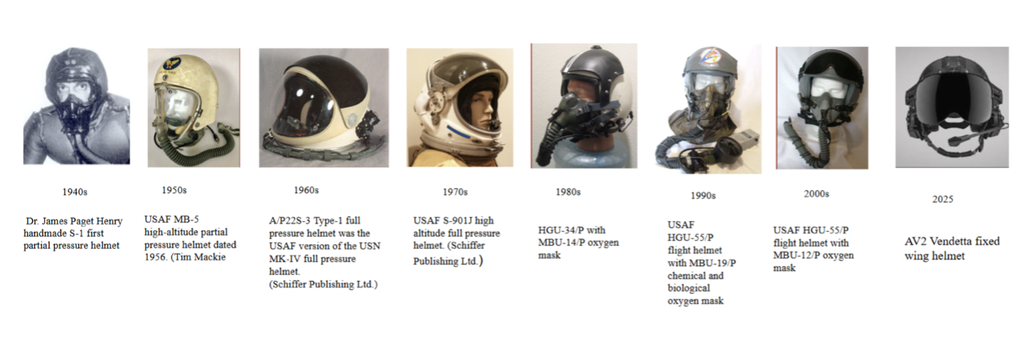
During the 1960s Gemini program, helmet design evolved beyond the basic, military-style helmets used in the earlier Mercury missions. New visor materials were introduced to shield astronauts from intense sunlight, and communication systems were upgraded to support extravehicular activities. Apollo era helmets during 1970s, added more protection materials, such as fireproof outer layer, and provided micrometeoroid shielding. From the 1980s to 2000s, improved communication and modular designs were introduced, enhancing better vision, safety, and customization. Modern helmets such as SpaceX’s models uses advancements in 3D printing technology and lightweight materials. communication advancements includes heads-up displays and cameras integrated life support, and overall safety systems.
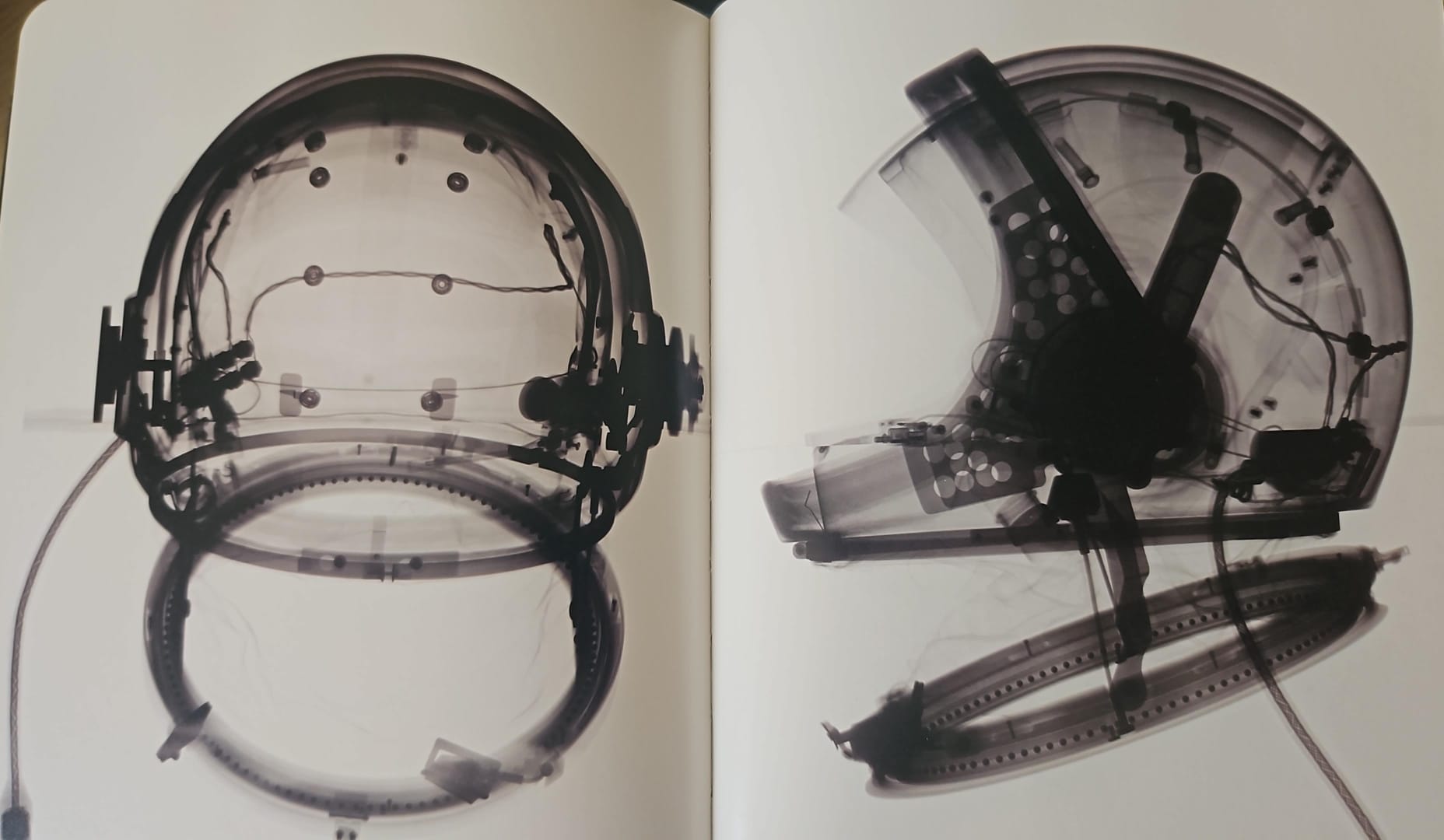
Spacesuits: The Smithsonian National Air and Space Museum Collection. Book by Amanda Young [2]
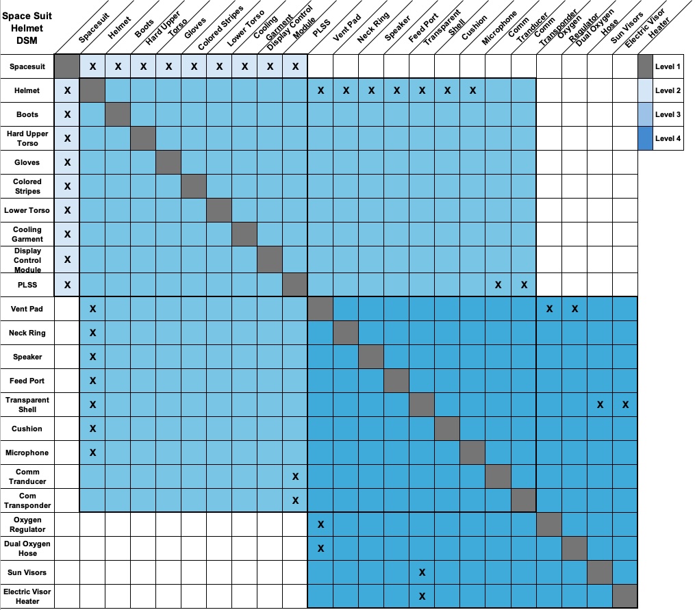
¶ 2. Design Structure Matrix (DSM) Allocation Matrix
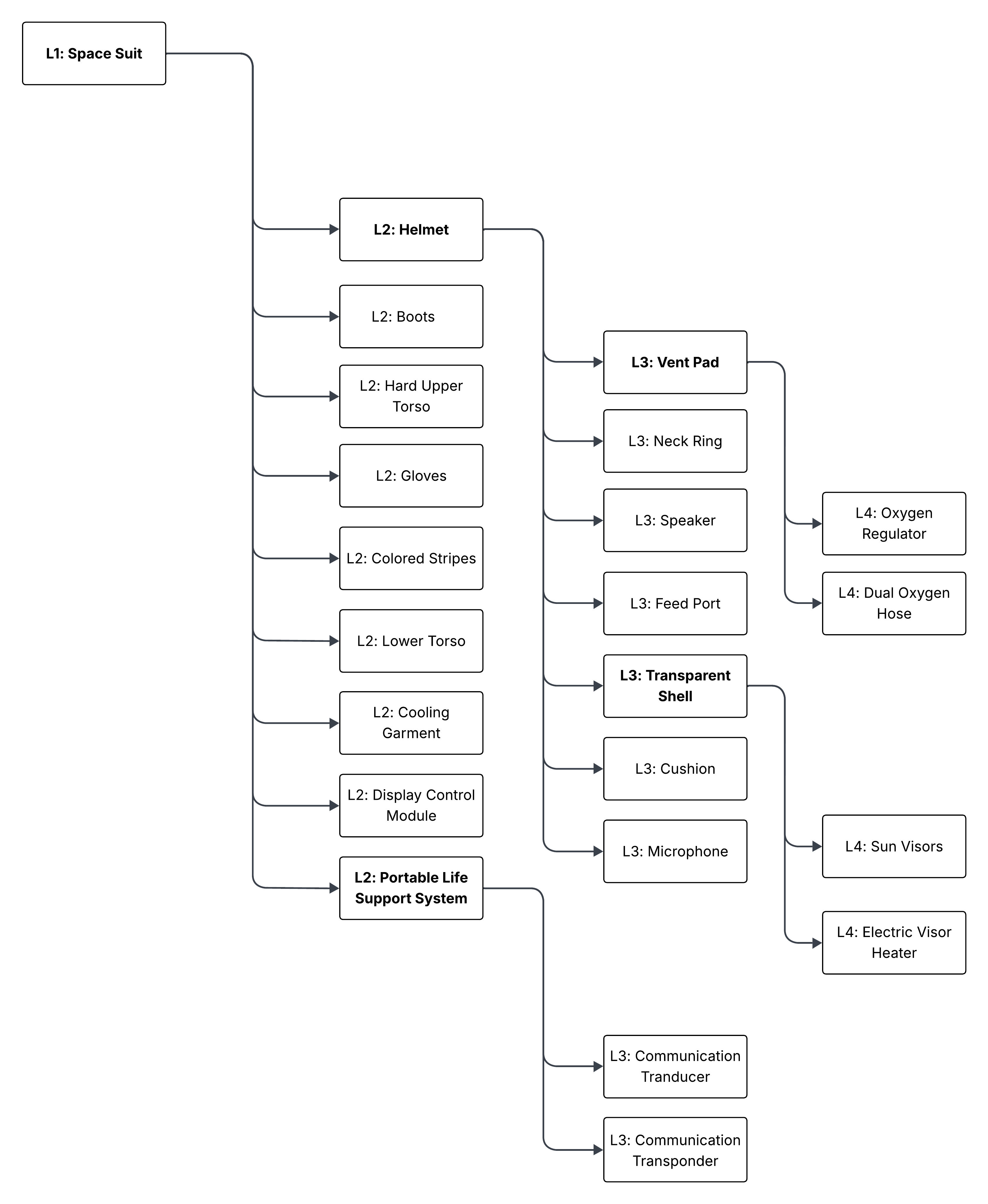
When viewing the spacesuit helmet through the lens of a DSM breakdown and allocation we can identify that the helmet is a level 2 product of the overall level 1 spacesuit. The spacesuit when decomposed can be broken down into the following main nine subcomponents below with additional subcomponent levels within those main components. Ultimately based on our DSM allocation matrix the spacesuit helmet is designed to support the overall goal and mission of the spacesuit working in tandem with other components such as the portable life support system (PLSS). Since we are focusing on the level 2 component spacesuit helmet we continue to decompose the helmet into its individual components which leads us to level 3 and 4 components such as the level 3 vent pad decomposing into the level 4 oxygen regulator and dual oxygen hose. DSM matrix allows complex systems such as the spacesuit and its helmet to be viewed in a less complex visual. It showcases relationships, interactions, and which elements are dependent on one another. Additionally, it is important to mention that this technology of the spacesuit helmet does not stand alone and it built upon the foundation of previous work done on the “Lunar EVA Space Suit" which is the level 1 system. Connections to level 2 and 3 components are also shown below to show the interdependencies of spacesuit helmet technology and its connection to existing roadmaps.
Table 1. DSM Allocation Interdependencies with other Roadmaps
| Level 1 Connection | [2SUIT] - Lunar EVA Space Suit |
| Level 2 Connection |
[2PBOGS] - Plasma-based Oxygen Generation in Space [2WHFWT] - Wearable Health Fitness Watches |
| Level 3 Connection | [2FSOC] - Free Space Optical Communications |
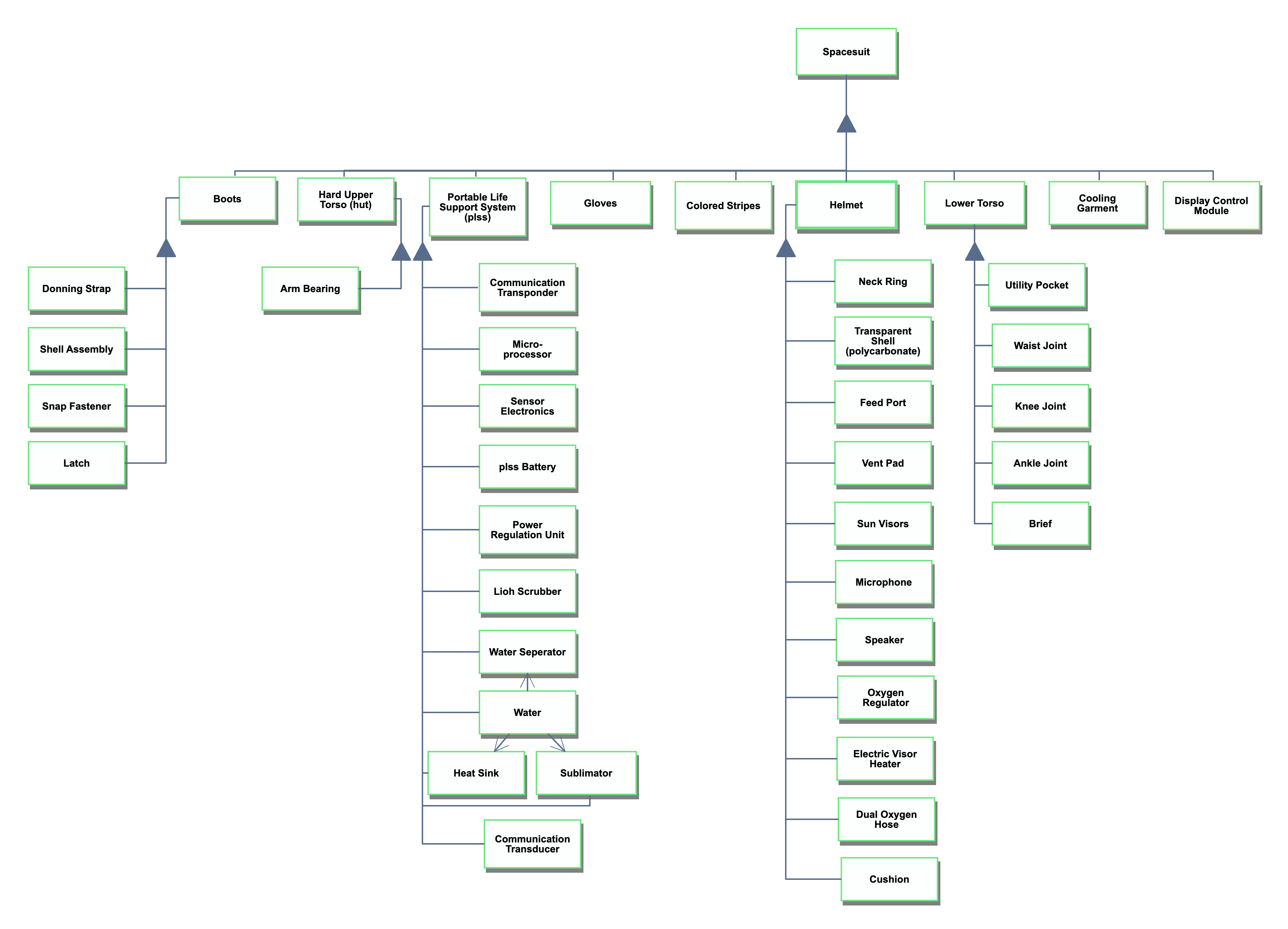
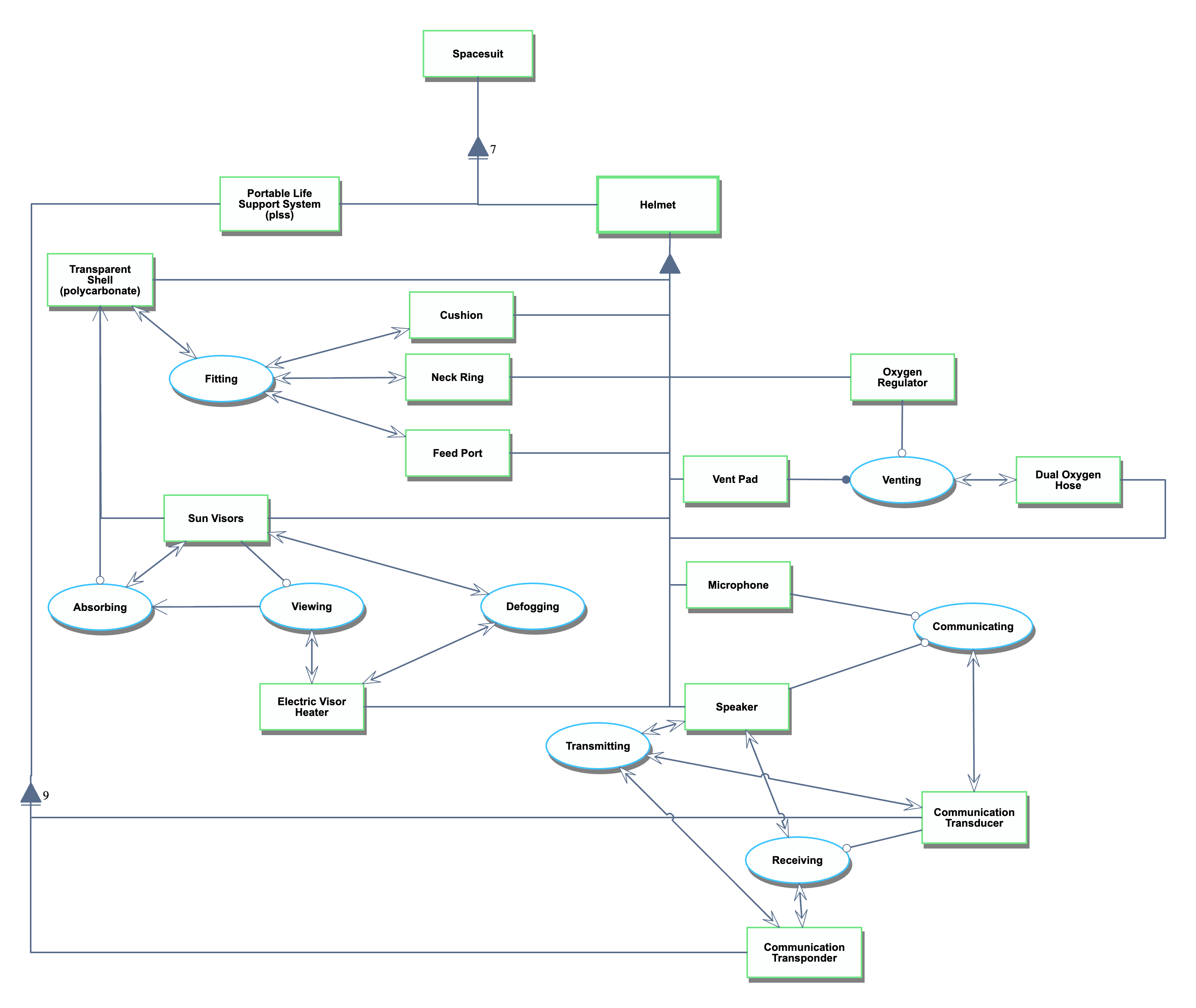
¶ 3. Roadmap Model using Object-Process Methodology (OPM)
Below are two OPM models starting with the level 1 space suit which focuses on the physical connections of the spacesuit purely to showcase that the spacesuit helmet is a component of a larger system with a greater purpose of protecting an astronaut. The level 2 or unfolded spacesuit helmet provides a more comprehensive OPM model showcasing not only the physical connections but the processes that occur between those components. In the decomposed OPM of the spacesuit helmet it the PLSS is included as components of the PLSS interact with the helmet with the main interactions showcased being the communication transponder and transducer.
¶ 4. Space Suit OPL
¶ 4.1 SD: Spacesuit OPL
1. Hard Upper Torso is a physical and systemic object.
2. Spacesuit is a physical and systemic object.
3. Gloves is a physical and systemic object.
4. Portable Life Support System is a physical and systemic object.
5. Colored Stripes is a physical and systemic object.
6. Helmet is a physical and systemic object.
7. Display Control Module is a physical and systemic object.
8. Lower Torso is a physical and systemic object.
9. Cooling Garment is a physical and systemic object.
10. Communication Transponder is a physical and systemic object.
11. Micro-processor is a physical and systemic object.
12. Sensor Electronics is a physical and systemic object.
13. plss Battery is a physical and systemic object.
14. Power Regulation Unit is a physical and systemic object.
15. Lioh Scrubber is a physical and systemic object.
16. Water Separator is a physical and systemic object.
17. Water is a physical and systemic object.
18. Sublimator is a physical and systemic object.
19. Heat Sink is a physical and systemic object.
20. Boots is a physical and systemic object.
21. Neck Ring is a physical and systemic object.
22. Transparent Shell is a physical and systemic object.
23. Feed Port is a physical and systemic object.
24. Vent Pad is a physical and systemic object.
25. Sun Visors is a physical and systemic object.
26. Utility Pocket is a physical and systemic object.
27. Donning Strap is a physical and systemic object.
28. Shell Assembly is a physical and systemic object.
29. Snap Fastener is a physical and systemic object.
30. Latch is a physical and systemic object.
31. Waist Joint is a physical and systemic object.
32. Knee Joint is a physical and systemic object.
33. Ankle Joint is a physical and systemic object.
34. Brief is a physical and systemic object.
35. Arm Bearing is a physical and systemic object.
36. Microphone is a physical and systemic object.
37. Speaker is a physical and systemic object.
38. Oxygen Regulator is a physical and systemic object.
39. Electric Visor Heater is a physical and systemic object.
40. Dual Oxygen Hose is a physical and systemic object.
41. Cushion is a physical and systemic object.
42. Communication Transducer is a physical and systemic object.
43. Spacesuit consists of Boots,Colored Stripes,Cooling Garment,Display Control Module,Gloves,Hard Upper Torso,Helmet,Lower Torso, and Portable Life Support System.
44. Portable Life Support System consists of Communication Transducer,Communication Transponder,Heat Sink,Lioh Scrubber,Micro-processor,Power Regulation Unit,Sensor Electronics,Sublimator,Water,Water Seperator, and plss Battery.
45. Water relates to Water Seperator.
46. Water relates to Sublimator.
47. Water relates to Heat Sink.
48. Helmet consists of Cushion,Dual Oxygen Hose,Electric Visor Heater,Feed Port,Microphone,Neck Ring,Oxygen Regulator,Speaker,Sun Visors,Transparent Shell, and Vent Pad.
49. Lower Torso consists of Ankle Joint,Brief,Knee Joint,Utility Pocket, and Waist Joint.
50. Boots consists of Donning Strap,Latch,Shell Assembly, and Snap Fastener.
51. Hard Upper Torso consists of Arm Bearing.
¶ 4.2 SD1: Spacesuit Helmet Unfolded OPL
1. Helmet from SD part-unfolds in SD1 into Cushion,Dual Oxygen Hose,Electric Visor Heater,Feed Port,Microphone,Neck Ring,Oxygen Regulator,Speaker,Sun Visors,Transparent Shell, and Vent Pad.
2. Helmet is a physical and systemic object.
3. Neck Ring is a physical and systemic object.
4. Transparent Shell is a physical and systemic object.
5. Feed Port is a physical and systemic object.
6. Vent Pad is a physical and systemic object.
7. Sun Visors is a physical and systemic object.
8. Microphone is a physical and systemic object.
9. Speaker is a physical and systemic object.
10. Oxygen Regulator is a physical and systemic object.
11. Electric Visor Heater is a physical and systemic object.
12. Dual Oxygen Hose is a physical and systemic object.
13. Cushion is a physical and systemic object.
14. Spacesuit is a physical and systemic object.
15. Portable Life Support System is a physical and systemic object.
16. Communication Transducer is a physical and systemic object.
17. Communication Transponder is a physical and systemic object.
18. Helmet consists of Cushion,Dual Oxygen Hose,Electric Visor Heater,Feed Port,Microphone,Neck Ring,Oxygen Regulator,Speaker,Sun Visors,Transparent Shell, and Vent Pad.
19. Spacesuit consists of Helmet and Portable Life Support System and seven more parts.
20. Portable Life Support System consists of Communication Transducer and Communication Transponder and 9 more parts.
21. Viewing relates to Absorbing.
22. Sun Visors relates to Transparent Shell.
23. Communicating is a physical and systemic process.
24. Communicating requires Microphone and Speaker.
25. Communicating affects Communication Transducer.
26. Viewing is a physical and systemic process.
27. Viewing requires Sun Visors.
28. Viewing affects Electric Visor Heater.
29. Fitting is a physical and systemic process.
30. Fitting affects Cushion,Feed Port,Neck Ring, and Transparent Shell.
31. Venting is a physical and systemic process.
32. Vent Pad handles Venting.
33. Venting requires Oxygen Regulator.
34. Venting affects Dual Oxygen Hose.
35. Transmitting is a physical and systemic process.
36. Transmitting affects Communication Transducer,Communication Transponder, and Speaker.
37. Absorbing is a physical and systemic process.
38. Absorbing requires Transparent Shell.
39. Absorbing affects Sun Visors.
40. Receiving is a physical and systemic process.
41. Receiving requires Communication Transducer.
42. Receiving affects Communication Transponder and Speaker.
43. Defogging is a physical and systemic process.
44. Defogging affects Electric Visor Heater and Sun Visors.
¶ 4.3 OPL Specifications
1. Hard Upper Torso is a physical and systemic object.
2. Spacesuit is a physical and systemic object.
3. Gloves is a physical and systemic object.
4. Portable Life Support System is a physical and systemic object.
5. Colored Stripes is a physical and systemic object.
6. Helmet is a physical and systemic object.
7. Display Control Module is a physical and systemic object.
8. Lower Torso is a physical and systemic object.
9. Cooling Garment is a physical and systemic object.
10. Communication Transponder is a physical and systemic object.
11. Micro-processor is a physical and systemic object.
12. Sensor Electronics is a physical and systemic object.
13. plss Battery is a physical and systemic object.
14. Power Regulation Unit is a physical and systemic object.
15. Lioh Scrubber is a physical and systemic object.
16. Water Separator is a physical and systemic object.
17. Water is a physical and systemic object.
18. Sublimator is a physical and systemic object.
19. Heat Sink is a physical and systemic object.
20. Boots is a physical and systemic object.
21. Neck Ring is a physical and systemic object.
22. Transparent Shell is a physical and systemic object.
23. Feed Port is a physical and systemic object.
24. Vent Pad is a physical and systemic object.
25. Sun Visors is a physical and systemic object.
26. Utility Pocket is a physical and systemic object.
27. Donning Strap is a physical and systemic object.
28. Shell Assembly is a physical and systemic object.
29. Snap Fastener is a physical and systemic object.
30. Latch is a physical and systemic object.
31. Waist Joint is a physical and systemic object.
32. Knee Joint is a physical and systemic object.
33. Ankle Joint is a physical and systemic object.
34. Brief is a physical and systemic object.
35. Arm Bearing is a physical and systemic object.
36. Microphone is a physical and systemic object.
37. Speaker is a physical and systemic object.
38. Oxygen Regulator is a physical and systemic object.
39. Electric Visor Heater is a physical and systemic object.
40. Dual Oxygen Hose is a physical and systemic object.
41. Cushion is a physical and systemic object.
42. Communication Transducer is a physical and systemic object.
43. Spacesuit consists of Boots,Colored Stripes,Cooling Garment,Display Control Module,Gloves,Hard Upper Torso,Helmet,Lower Torso, and Portable Life Support System.
44. Portable Life Support System consists of Communication Transducer,Communication Transponder,Heat Sink,Lioh Scrubber,Micro-processor,Power Regulation Unit,Sensor Electronics, Sublimator, Water, Water Separator, and plss Battery.
45. Water relates to Water Separator.
46. Water relates to Sublimator.
47. Water relates to Heat Sink.
48. Helmet consists of Cushion,Dual Oxygen Hose,Electric Visor Heater,Feed Port,Microphone,Neck Ring,Oxygen Regulator,Speaker,Sun Visors,Transparent Shell, and Vent Pad.
49. Lower Torso consists of Ankle Joint,Brief,Knee Joint,Utility Pocket, and Waist Joint.
50. Boots consists of Donning Strap,Latch,Shell Assembly, and Snap Fastener.
51. Hard Upper Torso consists of Arm Bearing.
52. Helmet from SD part-unfolds in SD1 into Cushion,Dual Oxygen Hose,Electric Visor Heater,Feed Port,Microphone,Neck Ring,Oxygen Regulator,Speaker,Sun Visors,Transparent Shell, and Vent Pad.
53. Helmet is a physical and systemic object.
54. Neck Ring is a physical and systemic object.
55. Transparent Shell is a physical and systemic object.
56. Feed Port is a physical and systemic object.
57. Vent Pad is a physical and systemic object.
58. Sun Visors is a physical and systemic object.
59. Microphone is a physical and systemic object.
60. Speaker is a physical and systemic object.
61. Oxygen Regulator is a physical and systemic object.
62. Electric Visor Heater is a physical and systemic object.
63. Dual Oxygen Hose is a physical and systemic object.
64. Cushion is a physical and systemic object.
65. Spacesuit is a physical and systemic object.
66. Portable Life Support System is a physical and systemic object.
67. Communication Transducer is a physical and systemic object.
68. Communication Transponder is a physical and systemic object.
69. Helmet consists of Cushion,Dual Oxygen Hose,Electric Visor Heater,Feed Port,Microphone,Neck Ring,Oxygen Regulator,Speaker,Sun Visors,Transparent Shell, and Vent Pad.
70. Spacesuit consists of Helmet and Portable Life Support System and seven more parts.
71. Portable Life Support System consists of Communication Transducer and Communication Transponder and 9 more parts.
72. Viewing relates to Absorbing.
73. Sun Visors relates to Transparent Shell.
74. Communicating is a physical and systemic process.
75. Communicating requires Microphone and Speaker.
76. Communicating affects Communication Transducer.
77. Viewing is a physical and systemic process.
78. Viewing requires Sun Visors.
79. Viewing affects Electric Visor Heater.
80. Fitting is a physical and systemic process.
81. Fitting affects Cushion,Feed Port,Neck Ring, and Transparent Shell.
82. Venting is a physical and systemic process.
83. Vent Pad handles Venting.
84. Venting requires Oxygen Regulator.
85. Venting affects Dual Oxygen Hose.
86. Transmitting is a physical and systemic process.
87. Transmitting affects Communication Transducer,Communication Transponder, and Speaker.
88. Absorbing is a physical and systemic process.
89. Absorbing requires Transparent Shell.
90. Absorbing affects Sun Visors.
91. Receiving is a physical and systemic process.
92. Receiving requires Communication Transducer.
93. Receiving affects Communication Transponder and Speaker.
94. Defogging is a physical and systemic process.
95. Defogging affects Electric Visor Heater and Sun Visors.
¶ 5. Figures of Merit (FOM)
¶ Helmet: EVA Life-Support
We focus on the helmet ↔ portable life support subsystem loop: how air is moved and conditioned, how CO₂ is removed and O₂ is managed, and how heat and humidity are controlled so the astronaut can think clearly, see clearly, and work safely for the full task duration.
Goals:
1) keep CO₂ low (safety/cognition), 2) avoid visor fog and overheating (comfort/visibility), 3) deliver enough mission time for the planned workload (endurance).
System pieces:
helmet volume (breathing zone), blower/valves, CO₂ scrubber, O₂ supply, water-cooling loop + heat exchanger/radiator, battery, sensors, and a controller tying it all together.
Table 2. FOM Breakdown
| # | FOM | Units | Rationale |
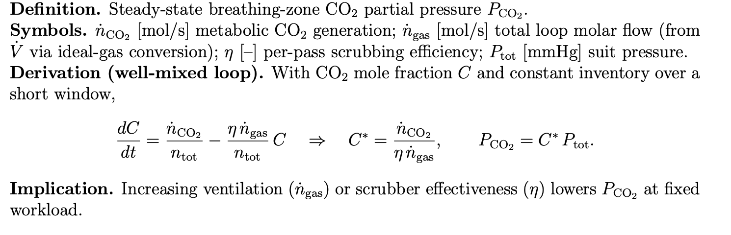
| 1 | Steady-state CO₂ partial pressure at mouth | mmHg | Primary safety/physiology outcome; limits cognitive/medical risk. |
| 2 | Thermal regulation authority | W | Can the system remove metabolic + environmental heat at setpoint? |
| 3 | EVA endurance per mass | hr/kg (hardware mass) | Clean efficiency/productivity metric for cross-design comparisons. |
| 4 | Pressure regulation (setpoint & stability) | kPa (±, dP/dt) | Maintains safe suit pressure and prevents barotrauma/ebullism; critical for all subsystems. |
| 5 | O₂ fraction control accuracy | %O₂ (±%) oxygen volume fraction | Ensures adequate oxygenation without waste or hypoxia risk. |
| 6 | Fault detection-to-mitigation time | seconds (s) | How fast the system recovers from dangerous transients. |
| 7 | CO₂ removal capacity | mmol/min (or L CO₂/min) | Core scrubbing performance; sets allowable metabolic rate and duration. |
| 8 | Airflow delivery range (continuous) | L/min | Guarantees breathing comfort across workloads; ties to blower capacity. |
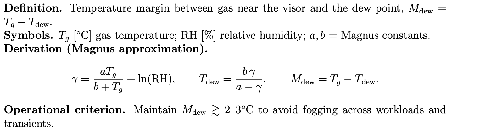
| 9 | Dew point margin at visor | °C | Anti-fog visibility; integrates humidity and temperature control. |
| 10 | Helmet air-velocity uniformity | m/s (min/mean/max) | Prevents hot spots and fogging; improves comfort and visibility. |
| 11 | Humidity control | %RH (±%) | Comfort, heat-transfer efficiency, and fogging risk. |
| 12 | Visual field & clarity | deg (H/V FOV), % transmittance (haze %) | Situational awareness and task performance inside/outside the suit. |
| 13 | Reliability (blower/pump MTBF) | EVA-hours | Directly tied to risk, spares, and logistics planning. |
| 14 | Dust robustness | % capacity loss or ΔP/g dust | Lunar/Martian operations resilience; protects performance margins. |
| 15 | Specific power draw for ventilation | W per (L/min) | Electrical efficiency; key for battery sizing and mission duration. |
| 16 | Cooling specific energy (COP-like) | Wh per W | Thermal-loop efficiency; impacts battery and radiator sizing. |
¶ Theoretical Limit
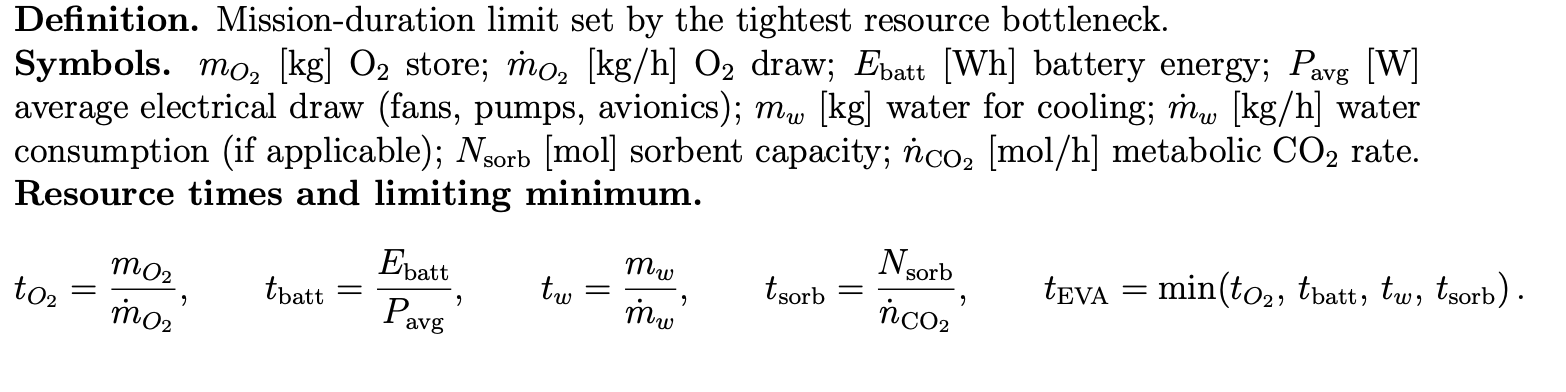
We analyze the spacesuit helmet + life-support system via a single, widely reported outcome FOM: Nominal EVA duration (hours). This integrates constraints from O2 storage, CO₂ scrubbing, battery energy, and thermal rejection, and cleanly aligns with operations documentation
Table 3. EVA duration over time
| Year | Duration [hr] | Tech note | Source / note |
| 1969 | 2.53 | Apollo | Apollo 11 EVA‚Äë1 (first lunar EVA) |
| 1972 | 7.62 | Apollo | Apollo 17 EVA‚Äë2 (longest Apollo EVA) |
| 1984 | 7 | Shuttle/ISS | Shuttle EMU planning max |
| 2001 | 8.93 | Shuttle/ISS | ISS record EVA (Helms & Voss) |
| 2005 | 7 | Shuttle/ISS | ISS EMU reference planning |
| 2013 | 8 | Shuttle/ISS | ISS ops upper cases (6–8 h typical) |
| 2020 | 8 | Exploration | Exploration xEVA ConOps (supports 6±2 h) |
| 2024 | 8 | Exploration | Exploration target (planning) |
| 2024 | 9.5 | Not operational (chamber) | xEMU thermal‚Äëvac endurance (test) |
| 1969 | 2.53 | Apollo | Apollo 11 EVA‚Äë1 (first lunar EVA) |
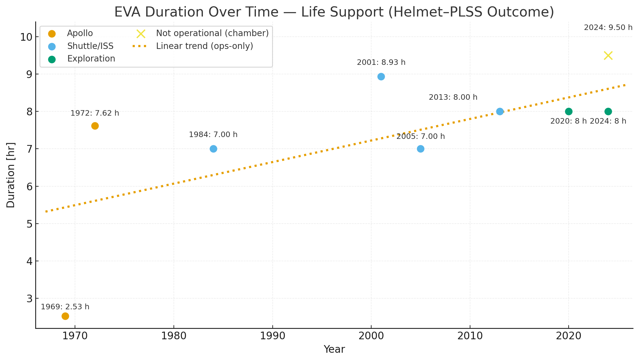
Figure 8. EVA duration vs. year for fielded operations, framed as a life-support (helmet–PLSS outcome) FOM. Ops points plateau near 7–8 h; the yellow ✕ shows a not-operational chamber endurance (~9.5 h). Dotted line is a linear trend on ops-only points.
We collected nominal EVA duration for previously fielded suits and recent exploration configurations. Durations were plotted by year of operational use/planning, with chamber endurance shown separately as “not operational.” This timeline captures how long a suited crew member can safely and productively remain outside the vehicle under nominal conditions. For our technology of choice, a helmet–PLSS life-support system, we analyzed the figure of merit EVA duration. We selected duration because it is (i) user-relevant to mission planners and crew, (ii) unit-clean and consistently reported across eras, and (iii) integrative of the coupled subsystems and human limits that determine EVA feasibility. In practice, longer duration generally implies that several subsystems (and the human) are all performing within bounds:
- Life Support Consumables: More O₂ storage/flow and CO₂ removal capacity enable longer time aloft; shortages here directly cap EVA length.
- Power & Thermal: Sufficient battery energy and heat rejection are required to maintain avionics, pumps, fans, and crew thermal balance over the full sortie.
- Helmet–Crew Factors: Work of breathing (pressure drop/vent path), comfort/thermal load, visibility/communications, hydration, and fatigue determine how much of the consumables envelope is actually usable in operations.
While longer EVA windows can increase task coverage and schedule flexibility, they come with trade-offs: carrying more consumables or thermal capacity can drive mass/volume, complexity, and risk; human fatigue and hydration logistics also become more challenging. Therefore, even if hardware demonstrates longer endurance in chambers, nominal operations still plan within a conservative 6–8 hour band.
Results. The data show a rapid rise from early Apollo (~2.5 h) to Shuttle/ISS capability (~7–8 h), followed by a long plateau. An early-era exponential fit indicates ~7%/yr improvement during takeoff, but the trajectory since the mid-1980s behaves like a saturating S-curve as multiple bottlenecks bind. A ~9.5 h chamber endurance demonstrates hardware headroom, yet it has not been adopted as a nominal ops duration.
Implication for design. EVA duration sits in the Slowing into Stagnation phase of the lifecycle (Fig. 4-15). Near-term gains are most likely from efficiency improvements (lower work of breathing, better thermal rejection per kg, smarter tasking/hydration) rather than simply adding more consumables. The practical asymptote for operational EVA duration is ~8–10 hours, with current planning anchored around ~7–8 hours [4, 5].
¶ 6. Alignment of Strategic Drivers: FOM Targets
This section links our company strategic drivers to the Helmet ↔ PLSS interface and the specific FOMS we will track on the roadmap. Each row states, in plain language, how the roadmap aligns and which way the FOMs should move to create value (↑ increase is good, ↓ decrease is good).
| Number | Strategic Driver | Alignment and Targets |
|---|---|---|
| 1 | Protect crew physiology: stable breathing environment (O₂/CO₂/pressure). | The roadmap strongly aligns. We prioritize closed-loop control that holds breathing gases and suit pressure within safe bands. Targets (dir.): ↓ steady-state pCO₂ at mouth; ↑ O₂ fraction control accuracy (↓ error); ↑ pressure regulation stability(low dP/dt overshoot); ↑ airflow delivery range to cover rest→peak workloads. |
| 2 | Keep the visor clear and the crew thermally comfortable. | Aligns. Helmet airflow and heat-/moisture management are shaped to prevent fogging while avoiding hot/cold spots. Targets (dir.): ↑ dew-point margin at visor; ↓ humidity excursions (%RH within band); ↑ helmet air-velocity uniformity (min↑, max peaks↓); ↑ visual field & clarity (FOV↑, haze↓). |
| 3 | Provide thermal authority for high-workload EVAs without over-sizing. | Aligns. We co-design the interface and cooling loop to reject metabolic + environmental heat efficiently. Targets (dir.): ↑ thermal regulation authority (W); ↓ cooling specific energy (Wh per W); ↓ specific power draw for ventilation (W per L/min); ↑ EVA endurance per mass (hr/kg) for an efficiency win. |
| 4 | Reliability and graceful fault management. | Aligns. Sensing, controls, and mechanicals are architected for predictable behavior under faults and quick recovery. Targets (dir.): ↑ reliability (blower/pump MTBF); ↓ fault detection-to-mitigation time; ↑ pressure setpoint stability after disturbances. |
| 5 | Dust-tolerant, serviceable interfaces for lunar ops. | Aligns. Interfaces, seals, and ducts are designed for regolith abrasion and quick turnaround between EVAs. Targets (dir.): ↓ capacity loss or ΔP per g dust (↑ dust robustness); ↓ haze/optical scatter from contamination; maintain airflow spec post-cleaning. |
| 6 | Minimize PLSS burden: power, mass, and integration impacts. | Partially aligns now (bench data) with full alignment after enclosure/firmware iterations. Targets (dir.): ↓ specific ventilation power; ↓ cooling specific energy; ↑ EVA endurance per mass so capability grows faster than hardware burden; maintain EMI/EMC headroom while logging key parameters to ops DB. |
| 7 | Operational simplicity | Aligns. Self-tests and guided procedures cut pre-EVA friction and reduce cognitive load. Targets (dir.): ↓ time to recover from transients (proxy: fault detection-to-mitigation); ↑ pressure/flow stability during mode switches; maintain visual clarityand uniform airflow during don/pressurize. |
| 8 | Mission assurance and schedule realism via modular upgrades. | Aligns. The interface stays modular so thermal, scrubbing, or sensor modules can be upgraded without full redesign. Targets (dir.): maintain or ↑ all reliability and clarity/comfort FOMs across module swaps; hold or ↓ power per performance when capabilities are added. |
Directionality (↑/↓) reflects the causal physics and operations we care about—for example, lowering steady-state pCO₂ at the mouth (↓) and raising visor dew-point margin (↑) both improve safety and performance. Because FOMs differ in units and ranges, we set targets per FOM on the timeline rather than forcing a single scale. Traceability from each driver to its supporting FOMs is maintained in the roadmap so design choices, test results, and risks roll up cleanly to mission value.
¶ 7. Positioning of Organization vs. Competition: FOM charts
The competition in space suit helmet development involves several leading aerospace and defense companies advancing diverse design strategies and the implementation of innovative material and communication technologies. David Clark and ILC Dover have long-standing legacies in aviation and astronaut equipment, supplying NASA with early helmet systems while continuously innovating in pressure garment design. Axiom Space is emerging as a new commercial competitor, developing integrated helmet architectures for future exploration missions. SpaceX’s space suit helmets are designed and manufactured entirely in-house , using additive manufacturing to embed electronics and life-support interfaces with built-in heads-up displays.
Competitive analysis of space suit helmet technology fundamentally revolves around key Figures of Merit that directly impact astronaut safety, performance, and mission success. These include pressure integrity to ensure life-supporting pressurization in the vacuum of space, optical quality for unobstructed and distortion-free vision, and advanced radiation protection against solar and cosmic rays [6].
Table 4.Competitive Analysis Table
| Developer | Year founded | Product name | Material | Product Innovation | System integration | Connected missions |
| Gentex (previously Gentex Corporation) | 1958 | HGU-56/P | Advanced composites, ballistic materials | Lightweight ballistic protection, modular integration | Communications, NVG, oxygen systems | U.S. Military Aviation, various Rotary Wing operations |
| David Clark | 1935 | Series K-10 | Impact-resistant plastics, aluminum, integrated audio | Pilot comfort, hearing protection, integrated headset | Integrated intercom/communication | U.S. Military Aviation, NASA flight deck support |
| ILC Dover | 1969 | EMU Helmet | Polycarbonate shell, Anodized aluminum | Pressure bubble design, thermal and radiation protection | Life support and communication | Space Shuttle missions, International Space Station EVAs |
| SpaceX | 2002 | SpaceX EVA Spacesuit helmet | 3D-printed parts, a polycarbonate visor coated with copper and indium tin oxide | Integrated heads-up display | Telemetry, suit sensors | Polaris Dawn private spacewalk, Crew Dragon missions |
| Axiom Space | 2016 | AxEMU Visor System | High-Definition Optics materials by Oakley | Oakley’s HDO visor | 4G/LTE communications, LED lights | Artemis program lunar missions, Axiom Mission 1 and plans for lunar EVAs |
¶ 8. Technical Model: Morphological Matrix and Tradespace
¶ Technical Models
This section formalizes the technical models behind our Helmet ↔ PLSS FOMs and the sensitivity study that feeds the tornado charts. For each FOM, we state the definition, symbols, and a compact derivation so the causal path from design choices → physics → mission outcomes is explicit. Assumptions (steady-state vs. transient windows, well-mixed control volumes, ideal-gas conversions, and component efficiencies) are chosen to keep models identifiable with data we can collect this term [7].
FOM 1: CO2 partial pressure at the mouth [mmHg]
FOM 2: Visor dew-point margin [◦C]
FOM 3: EVA endurance (nominal) [hr]
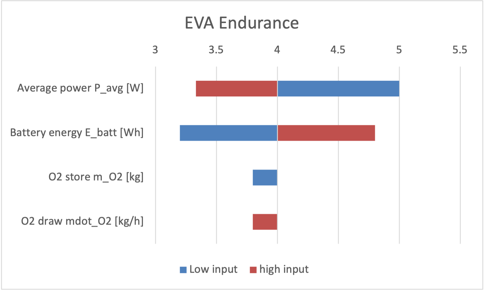
¶ Sensitivity Analysis Calculations using Finite Difference Gradients
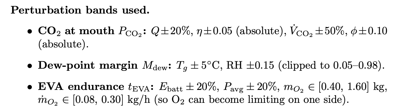
We compute local baseline sensitivities to see which design parameters most influence each FOM and in what direction. Using central finite differences with the same Low/High bands as the tornado charts, we report normalized elasticities.
Methods — finite differences. For each Figure of Merit (FOM) and parameter xi, we computed central finite-difference gradients and reported normalized sensitivities (elasticities):
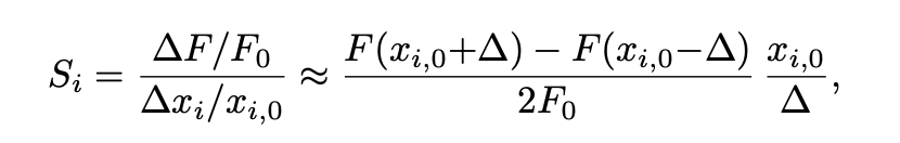
with F0 = F(x0) at the baseline x0. One parameter was perturbed at a time using the same Low/High bands as in the tornado charts; all other inputs were held at baseline. Positive Si indicates that the FOM increases when the parameter increases. For each Figure of Merit (FOM) and parameter xi, we computed a central finite-difference gradient and reported the normalized sensitivity. One parameter was perturbed at a time (others held at baseline). Positive Si means the FOM increases when that parameter increases. The same Low/High bands were used to generate the tornado charts.
Normalized sensitivities
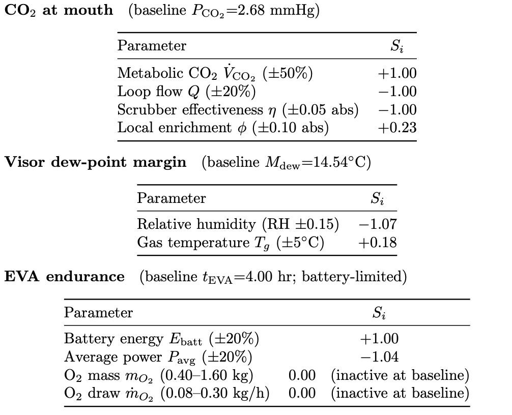
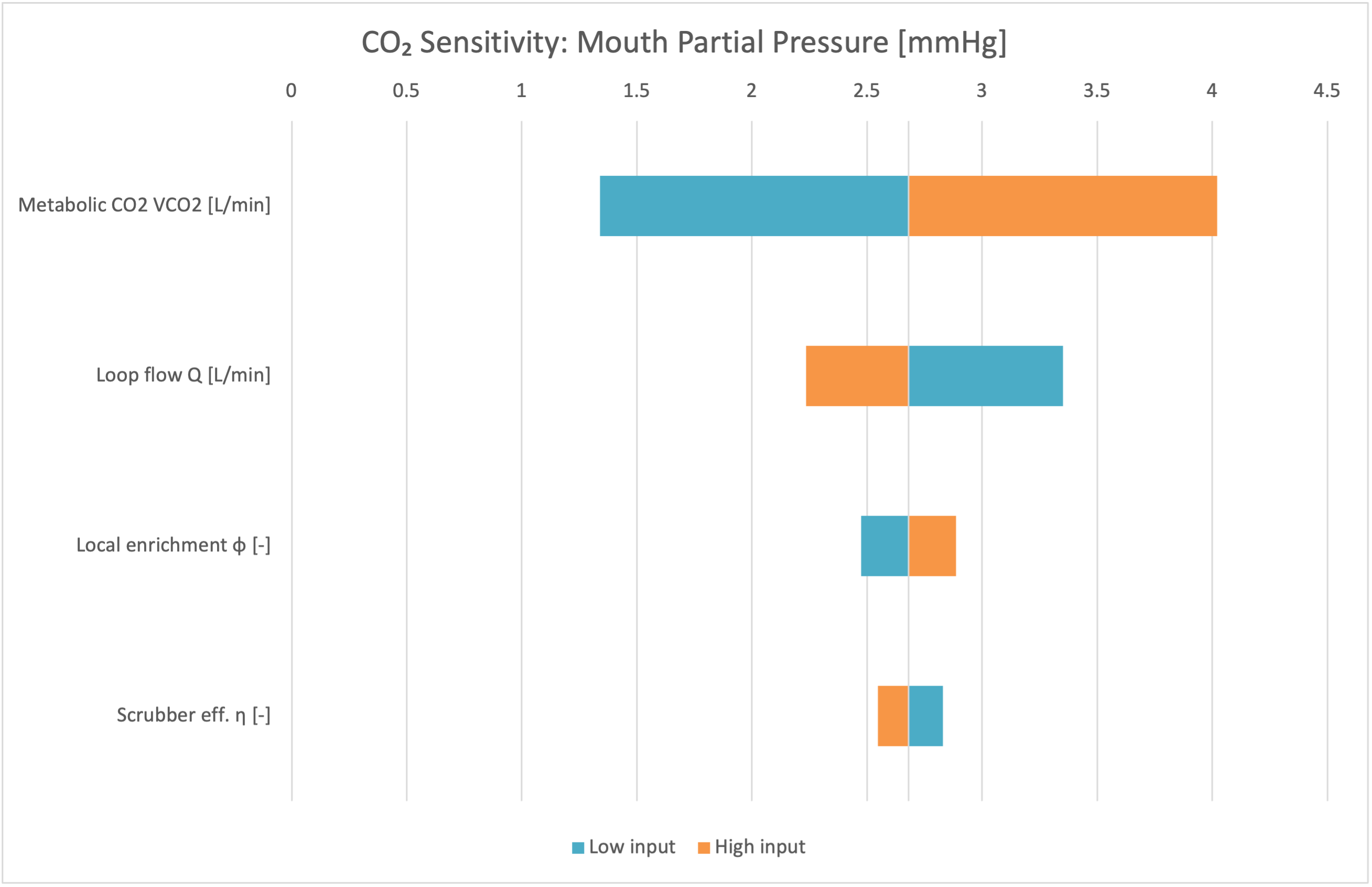
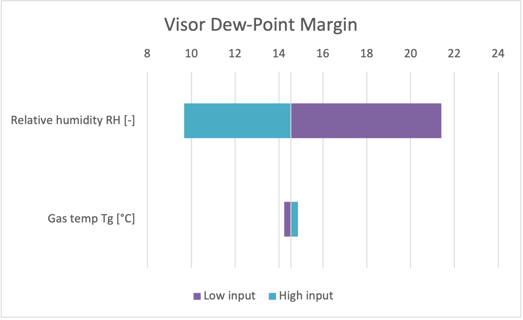
For each parameter xi we evaluated F(xi,0−∆) and F(xi,0+∆) and plotted those two FOM values as the left/right bars, with the baseline marked by a vertical line. Categories are ordered by F(xi,0+∆)−F(xi,0−∆) to form the tornado shape; the signed, normalized Si above correspond to the same perturbation [8]
¶ Tornado Charts
We have created the following tornado charts based off of the sensitivity analysis. We use different technical models and therefore have different input variables because each FOM is governed by different physics and constraints rather than being influenced by each other.
¶ Morphological Matrix
| Subsystem | Option A | Option B | Option C | Option D |
| CO2 removal | LiOH canister | Solid amine bed | Vacuum-swing amine (VSA) | Amine + booster micro-bed |
| Ventilation architecture | Single loop, helmet return | Dual loop (torso+helmet) | Dual loop + mouth jet | Recirc + localized extraction (chin) |
| Fan / blower | Centrifugal fan | Axial blower (low ΔP) | Dual redundant fans | Variable-speed BLDC + PID |
| Thermal rejection | Sublimator only | LCVG + sublimator | LCVG + radiator panel | LCVG + sub + PCM buffer |
| Coolant loop | Fixed flow | Valved variable flow | Micro-channel garment | Heat-pump assist (COP>1) |
| Water management | Open-loop sub (high m_dot_w) | Pulsed sub (moderate m_dot_w) | Regenerative radiator (low m_dot_w) | Evaporative wick (backup) |
| O2 supply & control | Fixed-orifice regulator | Servo regulator + PPO2 control | O2 pulse-demand | O2+N2 mix (testbed) |
| Gas sensing | NDIR CO2 + galvanic O2 | Paramagnetic O2 + NDIR | TDLAS CO2 + paramag O2 | Redundant dual-sensor |
| Helmet / visor | Standard visor | Hydrophilic anti-fog coat | Heated visor rim | Air knife over visor |
| Seals / leaks | Standard neck ring | Improved seal geometry | Active leak trim | Purge slot + quick-seal |
| Power module | Li-ion (baseline Wh/kg) | Li-ion high-energy (+15% Wh) | Li-ion + swap pack | Li-metal test (+30% Wh) |
| Comms / acoustics | Standard mic + fan | Noise-isolating mic | Ducted fan (–dBA) | Helmet baffles (−φ side-effect) |
Figure 12: Morphological Matrix (Helmet–PLSS Options): with qualitative options for each subsystem (in rows). Selecting one option per row defines a complete concept for analysis.
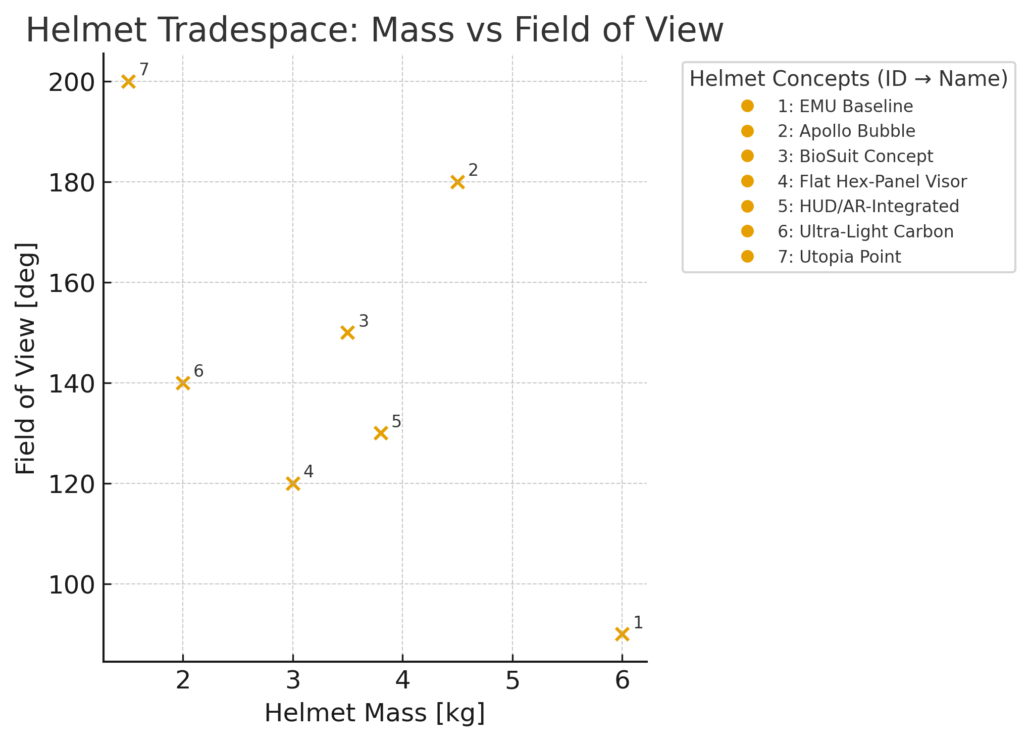
Tradespace
¶ 9. Financial Model: Technology Value (𝛥NPV)
To evaluate the feasibility of the proposed advanced EVA Helmet and PLSS subsystem, we developed a 20-year financial model incorporating projected revenues, operating costs, capital expenditures, working capital requirements, taxes, and discounting.
Revenue is assumed to begin in Year 5, reflecting the time required to reach TRL 6–7 through prototype development, vacuum chamber testing, PLSS interface integration, and human-rating evaluations. Revenue growth over time is driven by four sources, government contracts, commercial space partnerships, services and maintenance, and licensing with a balanced mix reflecting the evolving Artemis and commercial LEO ecosystem.
Operating costs are dominated by engineering labor, manufacturing, and subsystem testing. Capital expenditures are highest in the early years due to helmet fabrication, environmental chamber testing, sensor integration, reliability assessments, and PLSS compatibility verification. Working capital increases proportionally with revenue to account for inventory, production tooling, and testing capacity.
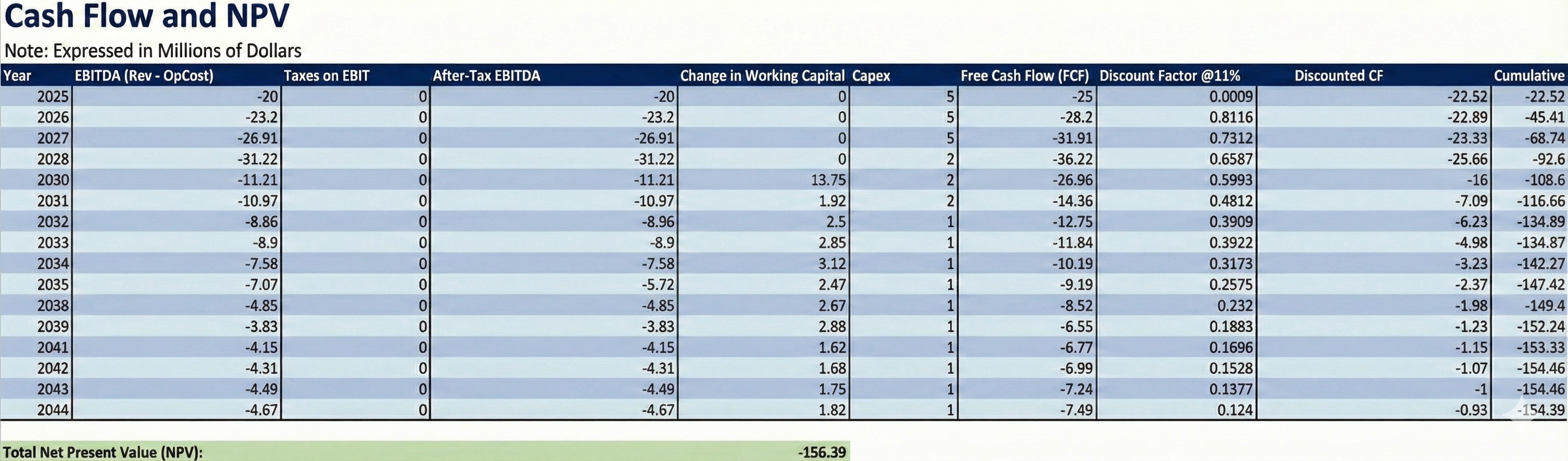
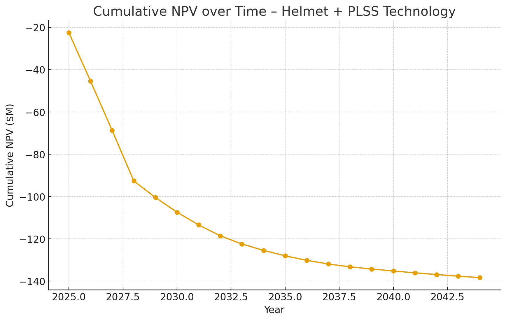
The cash-flow results, discounted at 11% to reflect the technical and programmatic risks of EVA life-support subsystems, show that cumulative NPV remains negative across the 20-year horizon. This behavior is expected: EVA hardware is extremely expensive to develop, has long certification timelines, and is produced in very low volumes. As a result, even moderate revenues are insufficient to overcome early development costs under conservative assumptions. This outcome is consistent with real-world EVA system economics, where strategic mission value, crew safety, performance, and reduced risk drive investment more than direct profitability.
Overall, the model highlights that while the technology is mission-enabling, it is not financially self-sustaining as a standalone commercial product. The results reinforce the importance of government support, long-term partnerships, and cost-sharing strategies for critical human-spaceflight subsystems [9, 10].
capital expenditures, working capital, and discounted cash flows used to compute cumulative NPV.
Table 5. Twenty-year Revenue Projection for the Helmet + PLSS subsystem
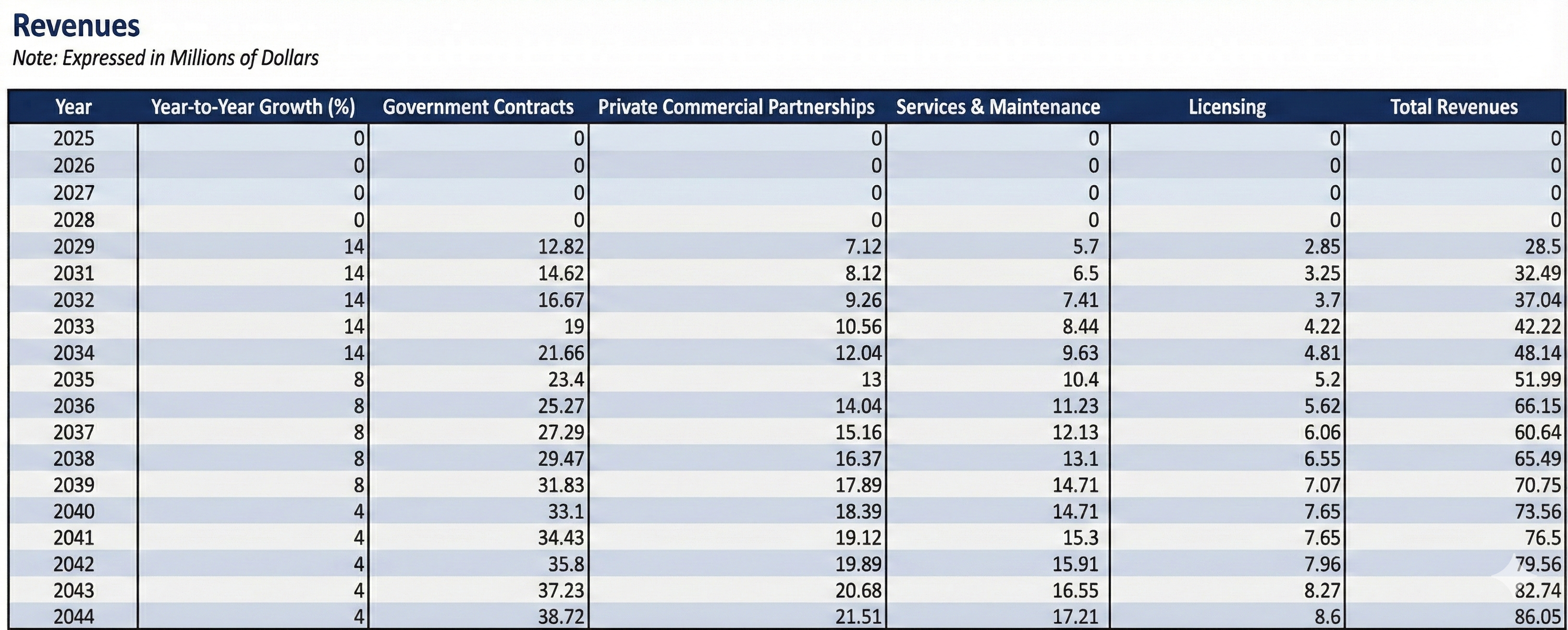
Table 6. Twenty-year Operating Cost Projection for the Helmet + PLSS subsystem
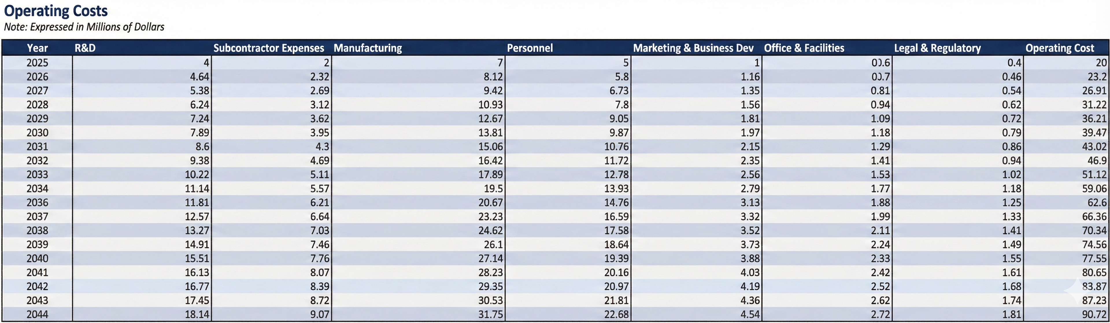
Table 7. Twenty-year Working Capital and Capital Expenditures Projection for the Helmet + PLSS subsystem
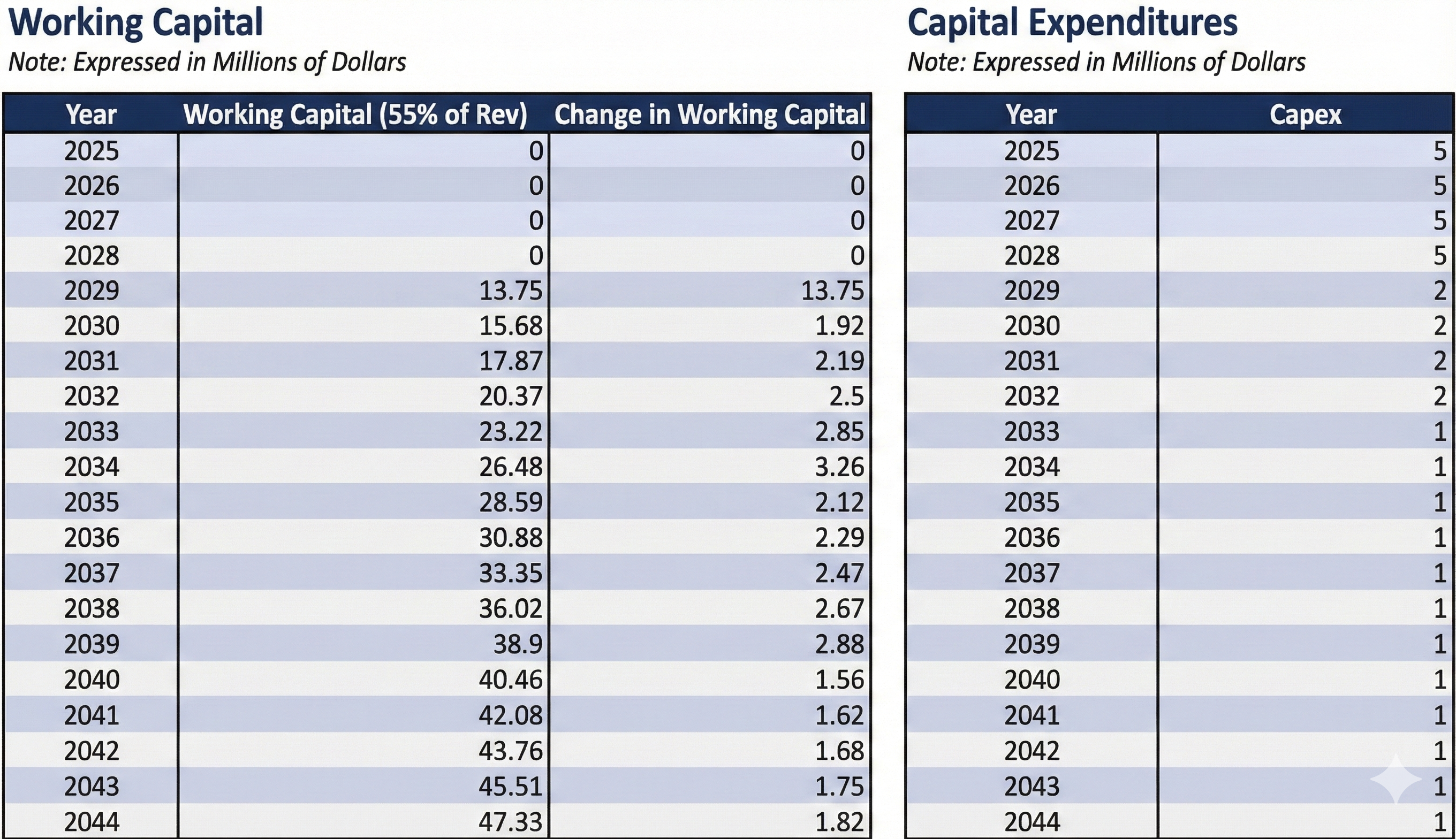
Table 8. Twenty-year Cash Flow and NPV Projection for the Helmet + PLSS subsystem
¶ 10. List of R&D Projects and Prototypes
1. Advanced Extravehicular Helmet Assembly (AEHA)
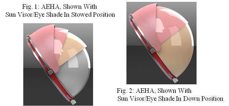
NASA’s AEHA R&D project develops a 13-inch hemispherical EVA helmet architecture, which is a demonstrated advantages in field of view, CO₂ washout, durability, and service life through the MK-III and Z-1 testbed suits. Air-Lock, Inc. advances this architecture from prototype to a flight-ready configuration by integrating a fully functional Extravehicular Visor Assembly (EVVA) and preparing the system for operational acceptability [11].
Organizational Responsibility:
- Mission Directorate: Space Technology Mission Directorate (STMD)
- Program: Small Business Innovation Research (SBIR/STTR)
- Lead Organization: Air-Lock, Inc.
- NASA Partner Center: Johnson Space Center
Objectives:
- Develop a complete Extravehicular Visor Assembly integrated into the hemispherical dome structure.
- Create a Verification and Validation (V&V) Test Plan that aligns with the current EMU Safety/Acceptance Documentation (S/AD) and Corrective Action Requests and Deficiencies (CARD) standards.
Benefits: - Delivery of a validated, flight-ready EVA helmet for integration into government spacesuits.
- Improved manufacturing methods for forming and coating large polycarbonate domes, enabling next-generation EVA visibility and protection.
- Advanced radiation-attenuating coatings applicable to windows on rovers, habitats, and pressurized stations.
Manufacturing processes capable of producing large, stress-free optical structures suitable for high-radiation environments.
2. EDS Technology (Helmet Visor and Stereo Camera) FY20 IRTD NextSTEP
NASA’s Electrodynamic Dust Shield (EDS) project explores the application of an electrostatic dust removal technology on curved, transparent surfaces like astronaut helmet visors and camera lenses for lunar and planetary missions. This setup generates electric field gradients that effectively clear dust particles, enhancing durability by shifting electrical breakdown from the surface into the more robust dielectric material, and improving overall system resilience and reliability.
Organizational Responsibility:
- Mission Directorate: Mission Support Directorate (MSD)
- Program: Center Independent Research & Development (KSC IRAD)
- Lead Organization: NASA Kennedy Space Center (KSC)
- NASA Partner Center: Johnson Space Center (JSC)
Objectives:
- Implement the EDS technology on transparent curved substrates such as helmet visors to validate applicability for astronaut EVA helmets.
- Integrate the EDS system on RASSOR camera lenses to reduce dust accumulation during regolith handling operations.
- Develop a single-phase, spatially dependent electric field design that improves electrode durability, maintains functionality despite partial damage, and provides a protective "safe zone" to shield astronauts from high electric fields.
Benefits:
- Effective dust removal from critical surfaces, reducing hazards associated with abrasive and electrostatically charged lunar and Martian dust.
- Enhanced system reliability through robust electrode design mitigating surface breakdown failures.
- Protection of astronauts from electric field exposure by a grounded safe zone embedded within the design.
- Extended applicability to other extravehicular suit components and equipment, helping sustain long-duration surface missions by maintaining clear visibility and operational reliability [12].
3. Joint Augmented Reality Visual Informatics System (JARVIS): xEMU Spacesuit Heads-In Display Visual Aid to Enable Crew EVA Autonomy (JARVIS)
NASA’s Joint Augmented Reality Visual Informatics System (JARVIS) project develops an augmented reality (AR) heads-in display (HID) integrated with the Exploration Extravehicular Mobility Unit (xEMU) spacesuit to enhance crew autonomy and performance during extravehicular activities (EVAs). In support of Artemis lunar surface missions, JARVIS aims to provide astronauts with a dynamic visual aid that improves communication, situational awareness, and workload management while enabling interaction with mission control and surface payloads via innovative optics and user interfaces [13].
Organizational Responsibility:
- Mission Directorate: Space Technology Mission Directorate (STMD)
- Program: Early Career Initiative (ECI)
- Lead Organization: Johnson Space Center (JSC)
- Partner Organizations: Collins Aerospace (industry)
Objectives:
- Design heads-in display hardware optimized for the unique optical characteristics of the xEMU spacesuit helmet.
- Develop user interfaces (UIs) introducing novel control and interaction concepts for both crew and mission control.
- Integrate display hardware into the xEMU and validate UI performance through analog testing in hybrid reality environments.
- Advance the technology readiness level of JARVIS from TRL 3 to TRL 5 to accelerate operational maturity.
Benefits:
- Enhanced EVA operational efficiency through real-time visual support reducing attentional loss and crew time.
- Improved crew-to-crew and crew-to-mission control communication and mission task coordination.
- Increased situational awareness and autonomy in extreme terrestrial and lunar surface environments.
- Foundation for future human-centric augmented reality applications in space exploration suits and systems.
4. SpaceX Advanced Extravehicular Activity (EVA) Spacesuit with Heads-Up Display (HUD)
SpaceX has developed an innovative EVA spacesuit designed for upcoming space tourist missions, such as the Polaris Dawn mission. This suit incorporates state-of-the-art technology, including 3D-printed helmet components, a visor with integrated Heads-Up Display (HUD), and an advanced camera system.
Organizational Responsibility:
- Mission Directorate: Commercial Spaceflight (Industry-led)
- Program: Polaris Dawn Private Space Tourism Mission
- Lead Organization: SpaceX
- NASA Partner Center: N/A (Commercial development)
Objectives:
- Design and develop a next-generation EVA spacesuit with enhanced mobility through advanced materials and helmet ergonomics.
- Integrate a HUD and camera system inside the helmet to provide real-time data visualization for mission monitoring.
- Utilize 3D printing technology for lightweight, customized helmet and visor components.
- Enhance ease of use with features like spiral zippers and ergonomically designed boots, borrowed from Falcon rocket materials.'
Anticipated Benefits:
- Increased situational awareness and safety for space tourists and astronauts during extravehicular activities.
- Improved wearer comfort and mobility
- Streamlined life support reliance, enabling a better integrated suit architecture.
TRL 8 to 9: The system has been tested extensively, including on the Polaris Dawn mission, which involved actual commercial spacewalks, demonstrating operational readiness in space environments.
5. Axiom Extravehicular Mobility Unit (AxEMU) for Artemis III
The AxEMU helmet for Artemis III features advanced coatings to enhance visibility and protect against harsh lunar lighting. It includes integrated helmet lights and an HD camera for navigation and recording. The visor system, developed with Oakley, offers deployable layers for light management, shielding against UV radiation, lunar dust, and impacts, with a gold coating providing solar protection at the lunar south pole. These features optimize optical clarity, radiation shielding, and physical protection for lunar surface operations.
Organizational Responsibility:
- Mission Directorate: Exploration Systems Development Mission Directorate (ESDMD)
- Program: Artemis III Mission
- Lead Organization: Axiom Space
- NASA Partner Center: Johnson Space Center (JSC)
Objectives
- Enhance astronaut visibility and protection with advanced coatings and integrated helmet lights.
- Accommodate a wide range of astronaut sizes and shapes
- Incorporate multiple redundant safety systems and onboard diagnostics for real-time health monitoring.
- Utilize regenerable carbon dioxide scrubbing and robust cooling within the helmet system.
- Continuously refine helmet design through underwater, thermal vacuum, and integrated tests.
Benefits:
- Improved visibility, safety, and comfort for extended lunar EVAs, including operations in extreme temperature conditions.
- Enhanced protection against lunar dust, solar radiation, and impacts through advanced visor and helmet architecture.
- Support of NASA’s Artemis III mission goals with a flight-ready, astronaut-tested helmet system integrated into the AxEMU spacesuit.
TRL 7 and 8: The suit is forecasted to enter its critical design review phase and undergo further integrated tests leading up to the Artemis III launch around 2026-2027.
¶ 11. Key Publications, Presentations and Patents
¶ 11.1 Publications & Presentations
Development of a Novel Helmet Support Assembly for NASA Orion Crew Survival Suit:
This publication focuses on the support assembly for the NASAs Orion crew survival suit which requires a unique helmet support system due to the unique environments of the mission. One of the main challenges the helmet support assembly (HSA) attempts to address is the water landings and countermeasures for when the helmet experiences dynamic loading. Another challenge this publication addresses is the balance between mobility, flexibility, safety, and range of motion. This is relevant to our EVA spacesuit helmet as the balance between restraint with mobility is a key challenge for any pressurized spacesuit helmet. Additionally, the publication compares designs that are both rigid and flexible ultimately showcasing that a balance between both improves both safety and comfort for the astronaut. Continued testing will occur in order to ensure the spacesuit helmet and HAS are ready for the lunar and Mars surface. Our team can take the unique countermeasure concept introduced and incorporate it into our EVA spacesuit helmet [15].
Space Suit Design: A Review of Current State and Perspectives on Requirements and Challenges
This paper reviews the current state of perspectives and challenges regarding spacesuit designs. It goes over the basic requirements and challenges astronauts face and the technology which allows them to survive the harsh conditions to perform EVA. The paper mentions the top requirement for EVA as the ability to be used in space and other celestial bodies mainly referencing the moon and Mars. Some of the major requirements for the spacesuit include radiation shielding, thermal regulation, micrometeoroid and orbital debris protection, hydration and waste management, and mobility. The next part of the paper which is more relevant to our EVA spacesuit helmet is the descriptions of the components of the spacesuit. The publication describes the helmet as a component that provides visibility in space. It is made to protect the astronaut from the sun and fogging from inside the helmet. The paper also mentions the use of communication devices mounted on the spacesuit helmet. This paper breakdowns each component of a spacesuit which our team will use to ensure that our DSM and OPM models are accurate [16].
¶ 11.2 Patents
Patent one: Spacesuit helmet display system G02B27/0172 – Head mounted, characterized by optical features
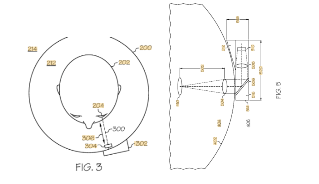
Figure 18. Description of patent one: This patent focuses on the future demands of vision required for EVA. This display system is mounted to the helmet and can generate images and redirect assembly orientation within the helmet. This display system which is mounted allows for the astronaut to command and generate images for display. Unique to this patent is the method for redirecting an image that is generated on the mounted display. The method will reflect the image toward a predetermined location using a mirror, which than adjusts the images based on the valid eye location volume [17].
Relevancy of patent one: This patent was specifically designed for future EVA suits as described in the abstract but also by NASA. Future EVA will require astronauts to conduct missions that may require assistance or could be enhanced by an overlay display showcasing steps or cautions that could be life threatening if not followed. Additionally, we believe this type of system will be valuable for the astronaut to have in order to keep track of their biometrics such as oxygen level, hydration, and blood pressure to name a few. The idea that astronauts can also command this display with their voice is powerful as it will provide another avenue of information that does not require the use of their hands or buttons.
Patent two: LED information cueing apparatus for spacesuit helmet G02B27/017 – Head mounted
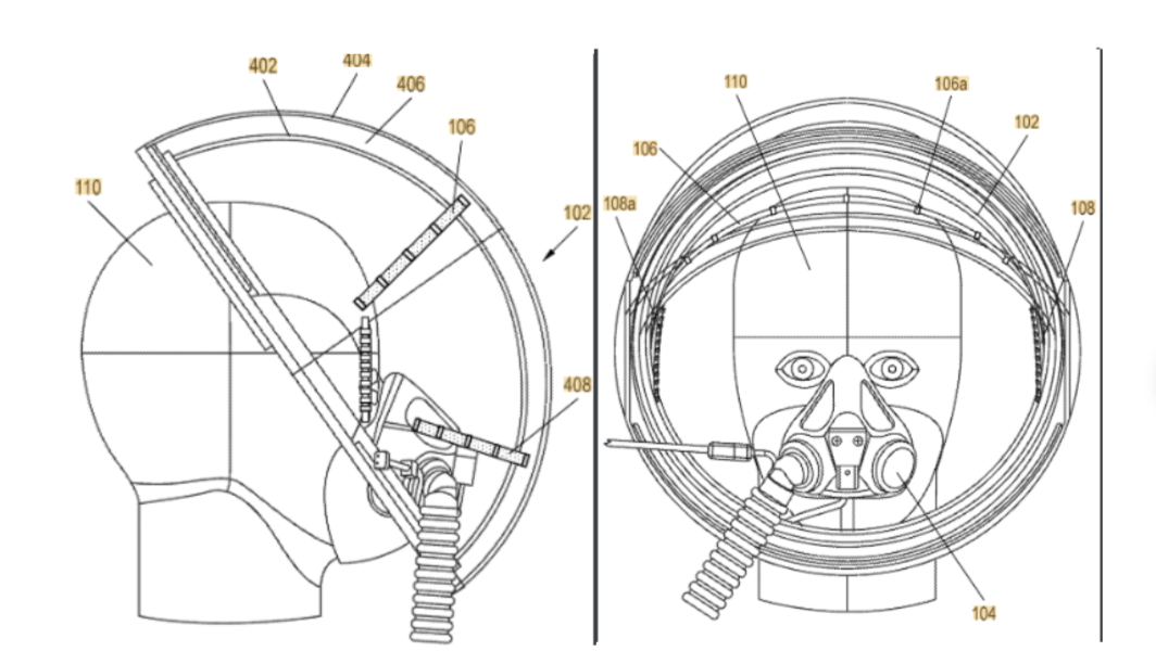
Figure 19. Description of patent two: This patent starts off describing the challenges of a single line crystal display (LCD) which is externally mounted to the astronaut’s chest and/or possibly on their arm requiring them to look outside their field of view. The actual patent is based on a LED array system that will communicate with other astronauts and the astronaut wearing the suit my emitting information through the LEDs. The information the LED arrays will provide will include the performance, consumable level, and position data of the astronaut. The LEDs will be placed within the peripheral field of view of the astronauts. Dimming of the LEDs and adjustments in brightness will indicate the status condition of the suit [18].
Relevancy of patent two: This patent is relevant not only to the spacesuit helmet but the spacesuit itself. While the patent describes that most of the LEDs will be placed in the peripheral field of view of the astronaut some of the external LEDs will also provide information important to other astronauts. It is important that communication is maintained on EVAs and by having biomarkers/information displayed in a manner where it is easy to see it will provide less guessing and introduction of error for the astronauts. In regards to the future EVA spacesuit we are developing the introduction of external attachments are important as future helmets are expect to provide more information to the astronaut. We believe that LEDs are an example of simple but redundant measure of providing this information that does not require much more time or energy to include. This simple but clever addition could provide valuable information to both the astronaut wearing the suit and the one looking at their fellow astronaut.
Patent three: Venting device for pressurized spacesuit helmet A62B18/04 – Gas Helmets
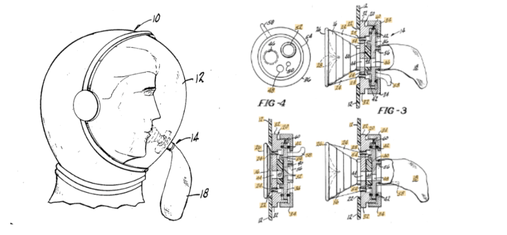
Figure 20. Description of patent three: This patent is a venting device port equipped with an external disposable pouch in order to manage vomit removal. Additionally, it also allows for purging, feeding, and close modes and has a seal near the O-rings around the neck. This patent provides a method for eliminating harmful waste in the helmet while simultaneously introducing as little obstruction as possible to the astronaut. While this patent is quite old it is the precursor to many design improvements which introduce a mechanism for the astronaut to manage and handle waste in the helmet [19].
Relevancy of patent three: As mentioned above this patent was one of the first inventions regarding waste disposal in spacesuit helmets. While the exact design of a pouch may be outdated the principles and underlying mechanism remain very relevant today. The idea of keeping the suit pressurized and not obstructing the view of the astronaut are still principles and FOMS focused today by spacesuit developers and NASA. What is probably more relevant is the mechanism in which the vent was sealed as that is a problem in all spacesuits, leaking of oxygen. What our team can take away from this patent is the idea of a vent mechanism that could ultimately serve multiple functions. While this patent focuses on waste removal there are other applications such as tools or helpful fixtures that could instead be mounted on the helmet to assist an astronaut.
¶ 12. Technology Strategy Statement
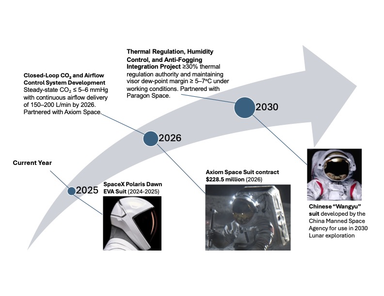
Our target is to develop a new EVA Spacesuit helmet with an Entry-into-Service (EIS) date of 2027. To achieve the target performance of continuous airflow of 150-2300 L/min and >30% thermal regulation we will invest in two core R&D projects.
The first R&D project is Closed-Loop CO₂ and Airflow Control System Development with a key milestone of demonstrating stable steady-state CO₂ ≤ 5–6 mmHg with continuous airflow delivery of 150–200 L/min by 2026. This milestone demonstrates safe CO₂ removal, uniform helmet air-velocity, and rapid fault detection-to-mitigation response, and enables longer EVA endurance per mass and improved cognitive/physiological safety margins.
The second R&D project is Thermal Regulation, Humidity Control, and Anti-Fogging Integration, with a target of achieving ≥30% thermal regulation authority and maintaining visor dew-point margin ≥ 5–7°C under lunar workloads by 2026. This capability is an essential enabling technology to achieve our technical and business goals for clear visual field & clarity, stable temperature control, and reliable cooling power.
Together, these R&D investments support our vision of a high-reliability EVA helmet that ensures breathable air quality, thermal comfort, fog-free visibility, and efficient power use by the year 2027 and position our organization for long-term capability, competitiveness, and operational impact.
¶ 13. References
[1] Smith, W. (2025). Axiom Space, Oakley partner on spacesuit visor for Artemis missions – Spaceflight Now. Spaceflightnow.com. https://spaceflightnow.com/2025/07/12/axiom-space-oakley-partner-on-spacesuit-visor-for-artemis-missions/
[2] Young, A., & And, A. (2009). Spacesuits within the collections of the Smithsonian National Air and Space Museum. Powerhouse Books.
[3] US Military Aviation - Flight Helmets. (2025). Salimbeti.com. https://www.salimbeti.com/aviation/helmets.htm
[4] Jones, E. (2018, June). Apollo Lunar Surface Journal. Www.nasa.gov. https://www.nasa.gov/history/alsj/
[5] NASA. (2025). International Space Station Spacewalks - NASA. Station Spacewalks. https://www.nasa.gov/international-space-station/space-station-spacewalks/
[6] Clark, D. (2024). Aviation | David Clark Company | Worcester, MA. Davidclarkcompany.com. https://www.davidclarkcompany.com/aviation/
[7] Bean, J., Schiller, N. H., & Fuller, C. (2017, May 24). Full Gradient Solution to Adaptive Hybrid Control. Nasa.gov. https://ntrs.nasa.gov/citations/20170005679
[8] Zhu, D., & Robinson, C. (2017, April 6). Advanced Thermal Barrier and Environmental Barrier Coating Development at NASA GRC. Nasa.gov. https://ntrs.nasa.gov/citations/20170005680
[9] NASA. (2017). NASA Office of Inspector General Office of Audits NASA’S MANAGEMENT AND DEVELOPMENT OF SPACESUITS. https://oig.nasa.gov/wp-content/uploads/2024/02/IG-17-018.pdf
[10] NASA. (2021). Office of Inspector General Office of Audits NASA’S MANAGEMENT OF THE ARTEMIS MISSIONS. https://oig.nasa.gov/wp-content/uploads/2024/02/IG-22-003.pdf
[11] Walters, D. (2025). NASA TechPort. Nasa.gov. https://techport.nasa.gov/projects/16571
[12] Walters, D. (2025b). NASA TechPort. Nasa.gov. https://techport.nasa.gov/projects/105643
[13] Walters , D. (2025). NASA TechPort. Nasa.gov. https://techport.nasa.gov/projects/154842
[14] Tangermann, V. (2024, May 7). SpaceX Reveals Spacesuit With Heads-Up Display Inside Helmet. Futurism. https://futurism.com/the-byte/spacex-reveals-spacesuit-heads-up-display
[15] François-Régis Bastide. (1977). Saint-Simon. International Conference on Environmental Systems.
[16] Bengi Bayar, Gülce Tuzcu, & Kaya, G. (2023, September 13). Space Suit Design: A Review of Current State and Perspectives on Requirements and Challenges. ResearchGate; unknown. https://www.researchgate.net/publication/373897543_Space_Suit_Design_A_Review_of_Current_State_and_Perspectives_on_Requirements_and_Challenges
[17] Dopilka, D., & Schuck, D. (2014, July 10). US9500868B2 - Space suit helmet display system - Google Patents. Google.com. https://patents.google.com/patent/US9500868B2/en
[18] Keith, C. (2021, April 14). US11910864B2 - LED information cueing apparatus for spacesuit helmet - Google Patents. Google.com. https://patents.google.com/patent/US11910864B2/en
[19] Gran, A., & Lang, R. (1967, February 27). US3473165A - Venting device for pressurized space suit helmet - Google Patents. Google.com. https://patents.google.com/patent/US3473165A/en
[20] Jones, A. (2025, February 14). Meet “Tansuo” and “Wangyu,” China’s next moon rover and astronaut spacesuit (video). Space. https://www.space.com/china-names-spacesuit-moon-rover-wangyu-tansuo
[21] Dinner, J. (2024, May 6). SpaceX reveals new EVA suit for 1st private spacewalk on upcoming Polaris Dawn spaceflight (video). Space.com. https://www.space.com/spacex-polaris-dawn-eva-spacesuit-reveal-video
[22] NASA. (2023, June). Extravehicular Activity and Human Surface Mobility - NASA. NASA. https://www.nasa.gov/suits-and-rovers/
[23] Generative AI (ChatGPT, Gemini) were used throughout the document primarily in support of the voice of the video and updating our revenue and cost graphs. The video was not made using AI but was edited by Ganit.
[24] Jonathan Stoppani provided HTML support to imbed the youtube video to the top of our website.