¶ Integrated Motors and Generators for Hybrid-Electric Aircraft
This is the technology roadmap for:
- 3IMG: Integrated Motors and Generators for Hybrid-Electric Aircraft
This technology falls under the “transforming energy” (1E) section of the 5x5 technology matrixThis is a “level 3” roadmap, indicating it is at the subsystem level. A “level 1” roadmap would indicate a market-level roadmap, “level 2” a system-level roadmap, and “level 4” a component-level roadmap.
¶ 1. Roadmap Overview
The integrated motor or generator system of a hybrid-electric aircraft is responsible for converting mechanical energy from the gas generator into electrical energy to be used by the propulsion system. The system boundary of this technology excludes the gas generator and propulsion system, only including components that are needed for converting energy. However, these systems are “integrated” into the higher-level aircraft system, meaning they interface mechanically with the gas generator and electrically with the propulsion system.
Electrical machines are the most critical component of the IMG system. Electrical machines are bidirectional machines that convert between mechanical and electrical energy. In generation mode, electrical machines extract shaft power and deliver electrical energy. In motor mode, they perform the opposite function, providing mechanical power to the shaft they are connected to. Traditionally, electrical machines have been used in industrial applications such as power plants, marine propulsion, and stationary power systems. However, with the demonstrated benefits of hybrid-electric propulsion systems for aircraft that enable designs with distributed propulsion, boundary layer ingestion, and unconventional fuselage designs, motors and generators have gained traction have gained traction for use in hybrid-electric aircraft. High-power and lightweight electrical machines can potentially enable aircraft noise and emissions reductions while mitigating the low energy density challenges of battery electric platforms.
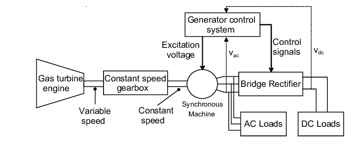
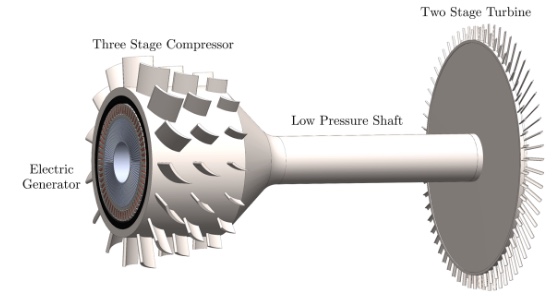
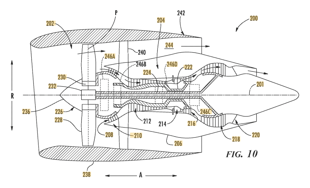
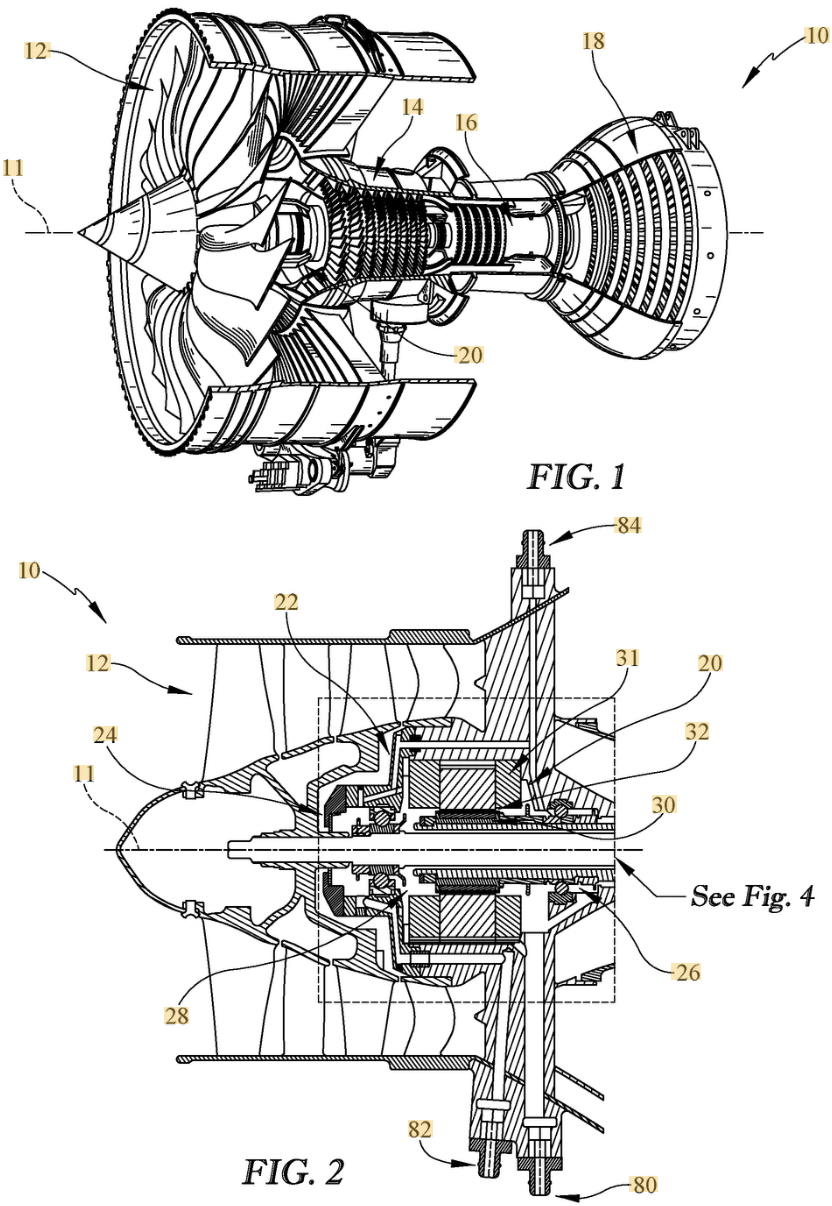
In most current systems, electrical motors and generators are separate from a power generation machine such as a gas turbine. The electrical machine is integrated into the system by connecting to the gas turbine through a shaft and gearbox, as shown in Figure 1. However, the shaft and gearbox add weight to the system and introduce additional lubrication, thermal management, and rotordynamic challenges, reducing the benefit of the hybrid-electric propulsion system. A more advantageous integration of a motor or generator is shown in Figure 2, where the electrical machine is embedded in the gas generator. This configuration reduces the weight required for integration and mitigates cooling and rotordynamic challenges.
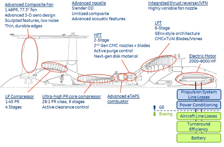
An important attribute of integrated motors and generators is their potential impact in a wide range of aircraft types and markets. A key area is the regional hybrid-electric aircraft market. In this area, Electra.aero [3] is developing a 9-passenger vehicle that uses a 600 kW turbogenerator connected to an electrical machine and in parallel with a battery to power a series of distributed propulsors on the wing. This enables the use of blown lift for short takeoff and landing capabilities with mechanically fixed propulsor mounting. Additionally, electrical machines have been proposed for use in turbo-electric concepts such as the NASA STARC-ABL [4] and in parallel-hybrid concepts such as the Boeing SUGAR Volt [5], shown in Figure 3.
¶ 2. Design Structure Matrix (DSM) Allocation
The Design Structure Matrix for this roadmap is shown in Figure 4.
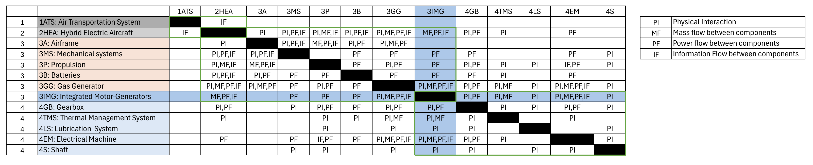
The technology hierarchy tree is as follows:
- 1ATS: Air Transportation System
- 2HEA: Hybrid Electric Aircraft
- 3A: Airframe
- 3MS: Mechanical systems
- 3P: Propulsion
- 3PS: Power Source
- 3B: Batteries
- 3GG: Gas Generator
- 3IMG: Integrated Motor-Generators
- 4GB: Gearbox
- 4TMS: Thermal Management System
- 4LS: Lubrication System
- 4EM: Electrical Machine
- 4S: Shaft
¶ 3. Roadmap Model using OPM
An Object Process Diagram (OPD) of this technology is shown in Figure 5.
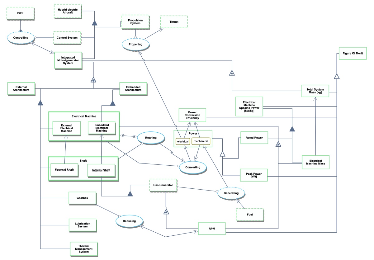
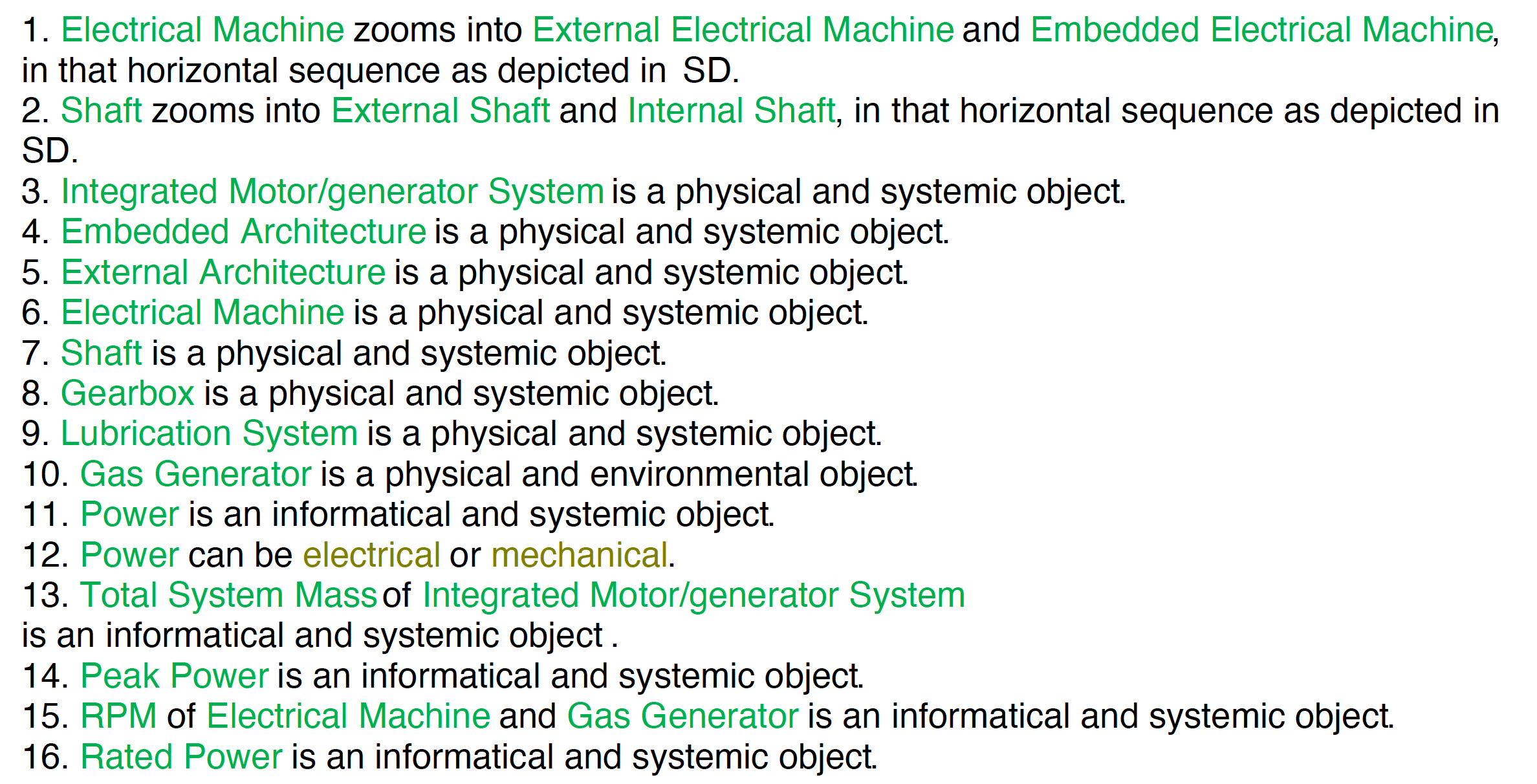
The list of components and links is as follows:

¶ 4. Figures of Merit (FOM)
Key figures of merit for integrated motors and generators are listed in the following table.
| Figure of Merit | Units | Definition |
|---|---|---|
| Electrical Machine Specific Power | [kW/kg] | Maximum continuous power of the electrical machine divided by its mass. The continuous power, or rated power, is the maximum power that can be supplied to the electrical machine indefinitely without failure. |
| Total System Mass | [kg] | Total mass of all components within the integrated motor or generator system. This includes the electrical machine as well as mechanical connections to a gas generator, such as a shaft and gearbox. Note that the full system mass is distinct from the electrical machine mass used in the electrical machine specific power definition. |
| Peak Power | [kW] | Maximum electrical power produced by or used by the generator or motor, respectively. Note that this is different from the maximum continuous power. The peak power is the maximum power that can be supplied to the electrical machine in short bursts. |
| Power Conversion Efficiency | [-] | A dimensionless quantity that is the ratio between output power and input power. In the case of a generator, input power is the shaft power out of the gas turbine and output power is the electrical power out of the electrical machine. |
| Rotational Speed | [RPM] | Rotation of the electrical machine per unit time. The rotation of the electrical machine may be measured in full rotations (such as rotations per minute) or in angle (such as radians per second). |
Each figure of merit listed above has its own significance in the larger system:
- Electrical Machine Specific Power: The electrical machine is the most important and most limiting component of the integrated system and holds the greatest opportunity for improvement. High power is desired from the machine, but low weight enables integration into an aircraft system. Therefore, the maximizing the specific power of the electrical machine is of primary importance for this technology.
- Total System Mass: Total mass of the system determines the benefit on the overall aircraft system. Incurring a large weight penalty can negate the benefit provided by electric propulsion.
- Peak Power: In modern aircraft, maximum engine power is typically set by required takeoff distance. Therefore, in the case of an integrated motor, the peak power determines takeoff performance.
- Power Conversion Efficiency: Power conversion efficiency quantifies lost energy, which translates to increased fuel burn for a given propulsive power.
- Rotational Speed: The required rotational speed of an electrical machine determines its ability to be embedded into the gas generator. The electrical machine must operate in a range consistent with the gas turbine, otherwise a gearbox is required.
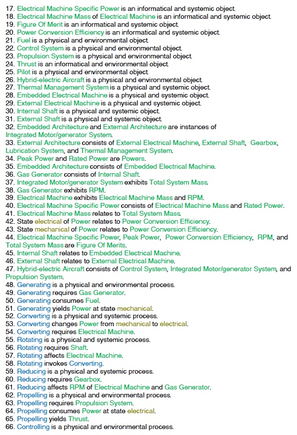
The performance of the electrical machine, and the system as a whole, is best described by the electrical machine specific power. This figure of merit has seen considerable investment and research recently, especially in the area of high-power “megawatt-class” machines. Examples of electrical machines that represent the state-of-the-art over time are plotted in Figure 6.
Listed from earliest to latest along the presented timeline, the electrical machines determined to represent the state-of-the-art are:
- Lange Antares Motor [6]
- Remy HVH250 [7]
- U.S. Navy Electric Ship Drive [8]
- Siemens SP260D [9]
- UIUC/NASA 1MW Machine [10]
- MIT GTL 1MW Machine [11]
Figure 6 indicates that the specific power of electrical machines is exhibiting exponential growth over time. The growth rate of the specific power is approximately 13.1% per year. While individual components of electrical machines have limits (maximum temperature, yield strength for example), there is no clear theoretical limit of the system. The subsystems comprising the machine can always theoretically be improved to prevent failure of specific components and therefore improve the performance of the entire machine.
¶ 5. Alignment of Strategic Drivers: FOM Targets
Key strategic drivers are listed in the following table. Most of these drivers relate to specific FOM targets that enable the potential fuel burn benefits of hybrid-electric propulsion.
| Strategic Driver | FOM Target | Current State-of-the-art |
|---|---|---|
| NASA's STARC-ABL hybrid-electric transport aircraft design predicts a 15% fuel savings [12]. To accomplish this, a target megawatt-class electrical machine specific power must be achieved by the year 2030. |
Electrical Machine Specific Power: 13 kW/kg by 2030 |
17.1 kW/kg (MIT 1 MW Machine [11]) |
| Integration of electrical machines into current civil aviation propulsion systems requires high shaft power to be produced or absorbed by the machines. Megawatt-class systems will be required for electric aircraft designs [11]. |
Peak Power: 1000 kW |
Continuous Power of 1000 kW for high-SP |
| High efficiencies are required to unlock the benefits of hybrid-electric aircraft. The NASA STARC-ABL design sets a benchmark assumption for power conversion efficiency for integrated generators by 2030 [12]. |
Power Conversion Efficiency: 96% by 2030 |
>96% Electrical Machine Efficiency, but embedded architecture necessary to achieve full system target |
| Embedding the electrical machine into a gas generator can provide significant weight advantages. However, to accomplish this, the electrical machine must be efficient at the operating RPM of the gas generator. |
Rotational Speed: matching available gas generators |
Not a common focus of electrical machine designs. |
As shown, both the specific power and peak power targets have been achieved by the MIT and University of Illinois megawatt-class projects. However, more effort must be directed to targets related to embedding the electrical machine in the gas generator. Current electrical machines achieve high efficiency, but the elimination of a gearbox is likely necessary to achieve this efficiency for the entire power conversion system. Likewise, matching the speed of the electrical machine and gas generator has not been a focus of past research. A brief amount of embedded design was performed by the MIT 1 MW team [11], but this is limited to conceptual design and does not feature in the assembled demonstrator.
¶ 6. Positioning of Organization vs. Competition: FOM charts
|
OEM |
Electric Machine Specific Power (kW/kg) |
Total System Mass (kg) |
Peak Power (MW) |
Power Conversion Efficiency |
Rotational Speed (RPM) |
Sources |
|---|---|---|---|---|---|---|
| Our Organization | 17.1 | - | 3.6 | 0.98 | max 5,000 | [11] |
|
Pratt & Whitney + Collins (RTX) |
9 |
110 |
1 |
0.98 |
2,000 |
[13,14] |
|
Safran |
3.5 - 4 |
250 – 286 |
0.5 - 1 |
0.94 |
15,00-4,500 |
[15] |
|
Honeywell |
7.9 |
127 |
1 |
0.97 |
19,000 |
[16] |
The commercial turbofan engine sector is a duopoly dominated by General Electric (GE) and Pratt & Whitney (P&W), with Rolls-Royce competing more strongly in the wide-body segment. Both GE and P&W develop and manufacture high bypass turbofan engines for narrow and wide body aircraft, competing head-to-head for long term supply positions on aircraft produced by Boeing and Airbus. A clear example is the Airbus A320neo, which can be powered by either the P&W Geared Turbofan or by the CFM LEAP-1A from the GE-Safran joint venture. In such oligopolistic markets, firms often compete through strategic technological commitments rather than price wars, forming a Bertrand duopoly with differentiated products focused on high performance and meeting certification standards.
However, when looking ahead, adjacent players such as Safran and Honeywell, which are traditionally focused on turboshaft and turboprop markets, are now investing in electrified turbomachinery and turbogenerators for hybrid-electric aircraft, partnering with startups like Electra.aero and emerging eVTOL companies. In contrast, GE and P&W may internally conduct research on future aircraft concepts, but primary remain strategically aligned with Boeing and Airbus, doubling down on the high-volume mid-haul market where demand exceeds supply. Their near-term strategy is focused on incremental efficiency improvements: R&D on next generation unducted fans and improved cooling technologies rather than investing in smaller, higher-risk hybrid propulsion systems. This is why established leaders like Rolls Royce and GE are not included in the table above, as they do not currently include electric machines in their portfolio or report associated performance metrics.
This strategic choice exemplifies the short-term and long-term progression of innovation. Currently, the duopolists are acting as defenders, defending the existing technology through continuous improvement to retaintheir market position. Whereas niche players pursue revolutionary architectures in smaller markets. Together, they behave in accordance with the game-theory patterns of technology competition in an oligopoly.
¶ 7. Technical Model: Morphological Matrix and Tradespace
In this section, the sensitivities of 2 figures of merit--electrical machine specific power and total system mass--are assessed. Additionally, the main trade space of integrated motors and generators is presented.
Morphological Matrix
The morphological matrix for integrated motors and generators is shown in the following table. Key design decisions include the electrical machine topology, the electrical machine flux type, cooling type, and installation architecture. The design selected by the MIT GTL 1 MW team, shown in green, is a permanent magnet (high SP), radial flux (high SP), air-cooled (compatible with aircraft engine installation) machine designed to be embedded (lower weight, fewer components) in the low-pressure compressor.
|
Electrical Machine Topology |
Wound-Field Synchronous |
Reluctance |
Induction |
Permanent Magnet |
|---|---|---|---|---|
|
Flux Type |
Axial |
Radial |
|
|
|
Cooling Type |
Air |
Water |
Oil |
|
|
Installation Architecture |
External |
Embedded |
|
|
Specific Power
The PhD research conducted by Dowdle [2] discusses the design of a high-specific-power, air-cooled electrical machine for aerospace propulsion applications. Dowdle presents a technical model that relates the power per unit volume of a simplified electrical machine to several design parameters. Adapting Dowdle's model to electrical machine gives specific power as a function of the electromagnetic shear stress (tau bar), length to radius ratio (l/r), and rotor tip speed U:
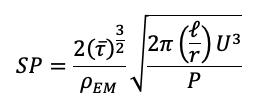
Dowdle proposes the design of a 3.6 MW electrical machine embedded into the low-pressure compressor of a gas generator. The design has the following parameters:
| Specifications [unit] | Design Value |
|---|---|
| Specific Power [kW/kg] | 14.8 |
| Electromagnetic Shear Stress [kPa] | 55.4 |
| Length-to-Radius Ratio | 1.51 |
| Tip Speed [m/s] | 230.28 |
| Rated Power [MW] | 3.6 |
Suppose we wanted to achieve a specific power of 17.1 kW/kg with this 3.6MW machine, the same achieved by the MIT GTL 1MW machine. Using the idealized specific power formula, the required increases to design parameters are given in the tornado chart Figure 7.
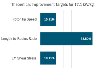
This reveals that increasing the rotor tip speed and electromagnetic shear stress are the most effective ways to increase specific power. However, this comes with material challenges.
Specific Power Trade Space
The major trade space in the design of an electrical machine is between power and specific power. The idealized specific power formula asserts that specific power is proportional to power to the negative-one-half power. However, this neglects the fact that the optimal or achievable EM shear stress, length-to-radius ratio, and tip speed change with the power of the machine. In a sequence of optimizations performed by Dowdle, it was determined that a more realistic law is specific power scaling with power to the negative-one-fourth power, which is more favorable for creating high-specific power, high-power machines. This scaling law effectively describes the shape of a Pareto front in the power-specific power trade space. The Pareto front can be placed on Dowdle’s survey of currently available electrical machines, as in Figure 8.
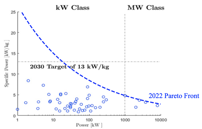
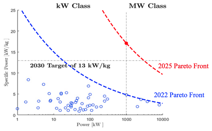
The Pareto front represents the practical limit of performance, and was therefore drawn such that all technology examples are on or below the front (lower SP or power). The achievement of a 1 MW machine with a specific power of 17.1 kW/kg by the MIT GTL in 2025 can be seen as a shift in this Pareto front, as in Figure 9.
Total System Mass
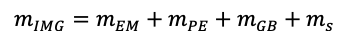
The total system mass of an integrated motor or generator system is the sum of the masses of the electrical machine, power electronics, gearbox, and shaft:
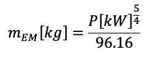
As shown previously, the state-of-the-art pareto front for electrical machines gives the specific power as a function of the rated power. Given the definition of specific power and this Pareto front, we have:
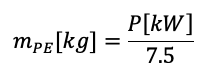
For the specific power of power electronics, the 2030 goal set by NASA for the STARC-ABL electrified aircraft design is 7.5 kW/kg [12]. Therefore:
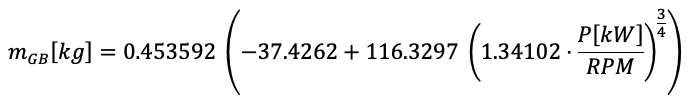
To conduct mission analysis on a hybrid-electric aircraft, Antcliff et al. [17] constructed a regression model that relates gearbox weight to power. Assuming a gear ratio of unity and a power input in kW, the regression model gives:
The amount of material necessary for the shaft is set by the torque on the shaft. The required shaft diameter for a given torque T is given by:
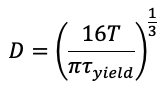
where tau_yield is the yield shear stress of the material. Since torque is power divided by angular velocity, the weight of the shaft as a function of the material density rho and an assumed constant length-to-diameter ratio and safety factor is:
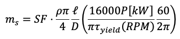
This yields a model for total system mass as a function of 3 design parameters: power, RPM, and yield strength to weight ratio. Assuming a safety factor of 2 and a length-to-diameter ratio of 4 for the shaft, the following design parameters are representative of the integration of the MIT GTL 1 MW electrical machine design:
| Specifications [unit] | Design Value |
|---|---|
| Total System Mass [kg] | 184.93 |
| Power [kW] | 1000 |
| RPM | 12500 |
| Yield strength to weight ratio [m^2/s^2] | 60727.04 |
To achieve just a 0.1% mass reduction, improvements to these parameters shown by Figure 10 are required:
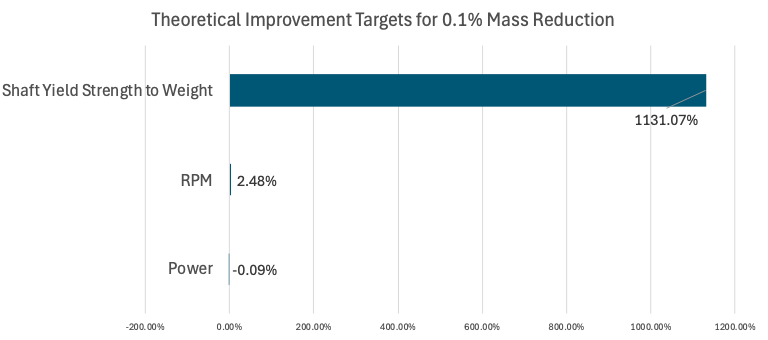
Note that a higher magnitude indicates a reduced sensitivity, as the parameter must change by a greater percentage to achieve the FOM goal. This tornado chart is dominated by the fact that the total system mass is extremely insensitive to the structural efficiency, and therefore the material, of the shaft. The root cause of this is that the mass of the shaft is a very small fraction of the total system mass compared to the electrical machine and gearbox. The mass of the system is by far the most sensitive to the power, which affects the mass of the electrical machine, gearbox, and shaft.
Note that for brevity, some parts of the analysis are omitted. A slightly more detailed version of the analysis can be found here: /2025_team_11/technical_model.pdf
¶ 8. Financial Model: Technology Value (𝛥NPV)
For this NPV analysis, we use United Airlines as the reference operator for cash flow scaling, while allowing several assumptions to be informed by broader industry trends. The financial perspective is intentionally taken from the perspective of an airline rather than an OEM, since the NPV ultimately reflects the incentives an airline would have to adopt integrated generators and motors. In practice, the key drivers behind such investment are the performance improvements and fuel-cost reductions the technology delivers, which translate directly into operational savings.
We assume that the airline begins investing in integrated generators six years before entry into service. This timeline is comparable to Alaska Airlines’ 2024 investment in JetZero, which is targeting a 2030 EIS [18]. This NPV is assuming a 2050 EIS based on the NASA AACES roadmap targeting a 2050 deployment. The investment United is assumed to make is distributed across six years prior to EIS:
- 2044: $100 million
- 2045: $150 million
- 2046: $200 million (increased R&D share)
- 2047: $250 million (testing, integration, early procurement)
- 2048: $150 million (certification and installation preparation)
- 2049: $100 million (pre-production and launch commitments)
This results in a total pre-EIS investment of $950 million, equivalent to approximately 15% of United’s 2024 annual capital expenditures [19].
Once the technology enters fleet service in 2050, we assume a baseline gearbox efficiency of 95% for the conventional turbofans (per NASA cycle-model references) [20]. When transitioned into a hybrid-electric aircraft with an integrated generator, the conversion efficiency is now 98% [13,14]. The resulting improvement yields a 3% reduction in annual fuel expenditure, corresponding to approximately $381 million in annual savings (based on United’s typical $12.7 billion annual fuel cost) [21].
Because more advanced propulsion components typically increase the maintenance burden, we assume a 5% increase in maintenance cost. Based on United’s 2024 Q3 statement (maintenance expenses of $866 million per quarter) [22], the annual maintenance cost is approximately $3.363 billion, implying an incremental cost of $173 million if applied across the full fleet (if hybridized). For this analysis, we assume only a portion of the fleet adopts the integrated motor generator starting in 2050. With an estimated fleet size of 1,000 aircraft [23], the maintenance delta per equipped aircraft is $173,000. Adoption ramps as follows:
- 2050: 50 aircraft
- 2051: 150 aircraft
- 2052: 300 aircraft
- 2053-2060: 500 aircraft
In addition to the fuel savings, we assume a further $40 million annual benefit for the first five years of service representing a modest discount on the power by the hour contract, equivalent to only 0.032% of the annual fuel cost, a conservative estimate.
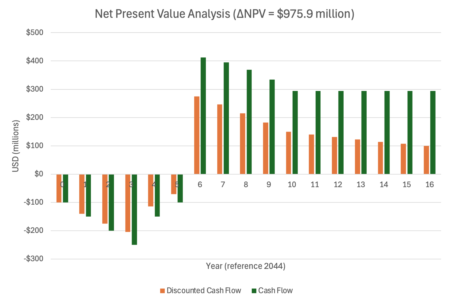
Therefore, in the first year of service (2050), the net operational benefit is approximately $395 million. Routine airline operating costs are excluded to keep this analysis focused on the incremental cash-flow change attributable to adopting the integrated generator technology. Accordingly, the NPV represents the delta relative to business-as-usual iterations rather than absolute cash flow. The result of this analysis is that investment will result in a positive NPV of $975.94 million and the discounting is taken with respect to year 0 = 2044 with a discount rate of 7%. This positive change in NPV indicates that the discounted future fuel savings and operational benefits outweigh the upfront development costs, supporting the case for investment in the technology. Figure 11 shows the net cash flow for each period (sum of fuel savings ( > 0) + increased maintenance cost ( < 0) + engine part by the hour discount ( > 0) + investment ( < 0)), as well as the discounted cash flows, with respect to time.
|
Year |
Period |
Discount Factor |
Net Cash Flow (millions) |
Discounted Net Cash Flow (millions) |
|---|---|---|---|---|
|
2044 |
0 |
1.0000 |
-$100.00 |
-$100.00 |
|
2045 |
1 |
0.9346 |
-$150.00 |
-$140.19 |
|
2046 |
2 |
0.8734 |
-$200.00 |
-$174.69 |
|
2047 |
3 |
0.8163 |
-$250.00 |
-$204.07 |
|
2048 |
4 |
0.7629 |
-$150.00 |
-$114.43 |
|
2049 |
5 |
0.7130 |
-$100.00 |
-$71.30 |
|
2050 |
6 |
0.6663 |
$412.00 |
$274.53 |
|
2051 |
7 |
0.6227 |
$395.05 |
$246.02 |
|
2052 |
8 |
0.5820 |
$369.10 |
$214.82 |
|
2053 |
9 |
0.5439 |
$334.50 |
$181.95 |
|
2054 |
10 |
0.5083 |
$294.50 |
$149.71 |
|
2055 |
11 |
0.4751 |
$294.50 |
$139.91 |
|
2056 |
12 |
0.4440 |
$294.50 |
$130.76 |
|
2057 |
13 |
0.4150 |
$294.50 |
$122.21 |
|
2058 |
14 |
0.3878 |
$294.50 |
$114.21 |
|
2059 |
15 |
0.3624 |
$294.50 |
$106.74 |
|
2060 |
16 |
0.3387 |
$294.50 |
$99.76 |
¶ 9. List of R&D Projects and Prototypes
Recent initiatives have been underway to produce high-specific-power, megawatt-class electrical machines for aircraft propulsion systems. This section lists a few of these projects.
The Ohio State University 1 MW Induction Motor [24]: In 2020, in collaboration with NASA, Dr. Codrin-Gruie Cantemir from The Ohio State University demonstrated a 1 MW electrical machine that uses an induction topology. This demonstrator set the record for megawatt-class induction machine power density at 4.7 kW/kg. It also set the absolute record for normalized power density among electrical machines at 2.6 W/(kg-RPM). As a next step in the project, a 2.7 MW demonstrator and eventually a 10 MW demonstrator will be developed. However, later in 2020, the demonstrator suffered a motor support failure which required a rebuild [25].
University of Illinois Urbana-Champaign 1 MW Permanent Magnet Machine [10, 26]: In 2016, in collaboration with NASA and Collins Aerospace, the University of Illinois began an effort to design and build a 1 MW electrical machine with a design specific power of 13 kW/kg, aligned with the NASA 2030 target for the STARC-ABL concept. In 2021, UIUC demonstrated the machine at a specific power of 15 kW/kg and over 96% efficiency, achieving their project goals.
NASA High Efficiency Megawatt Motor (HEMM) [27]: NASA Glenn Research Center is designing a 1.4 MW electrical machine with superconducting coils for electric aircraft applications. The concept has gone through preliminary design, but a demonstrator has not yet been built and tested. Certain components, such as the superconducting coils, have undergone risk reduction testing.
MIT Gas Turbine Lab 1 MW Machine [11]: The MIT Gas Turbine Lab, in collaboration with Mitsubishi Heavy Industries, is designing and testing a 1 MW permanent magnet electrical machine demonstrator. The machine has a design specific power of 17.1 kW/kg and represents the state-of-the-art in high-power electrical machine research. The GTL has conducted full speed tests of the machine and will begin adding load in late 2025 and 2026.
¶ 10. Key Publications, Presentations and Patents
¶ 10.1 Publications & Presentations
Research activity in electric, turboelectric, and hybrid-electric propulsion has increased significantly in the past decade, and the literature now reflects a shift in how propulsion systems are enabled. Across these publications, a consistent theme emerges: electric machines, motors, and generators, are no longer ancillary industrial hardware, but foundational elements of future propulsion architectures. By supplying electrical power rather than directly producing thrust, integrated machines create new design freedoms and motivate alternative configurations such as distributed propulsion, boundary-layer ingestion, and more.
The publications also highlight the broad application space for electric propulsion, spanning regional air mobility concepts to single-aisle demonstrators. Examples include Electra.aero’s blown-lift STOL aircraft powered by a 600 kW turbogenerator-battery system [3], and NASA’s SUSAN Electrofan concepts [28], which distributes power from an aft-mounted propulsor to multiple electric fans. These works collectively underscore why hybrid-electric architectures, given current battery energy density limits, are viewed as the most viable path for near-to mid-term aircraft electrification.
At the component level, recent work documents advancements in embedding electric machines with gas turbine cores, in comparison to traditional gearbox-coupled machines. Publications from MIT’s Gas Turbine Lab [11] demonstrate a low-pressure spool integrated machine achieving 17.1 kW/kg specific power and using engine bleed air for cooling, thereby exceeding prior state of the art benchmarks and surpassing NASA’s 2030 targets for aircraft electrical machines.
Across the literature, electric-machine specific power has risen at roughly 13% annually for two decades. Early demonstrators such as Siemens’ SP260D (5.2 kW/kg) [9] have been surpassed by megawatt-class machines from Honeywell [16], UIUC [10], and MIT [11], many now exceeding 15 kW/kg. Recent research programs reinforce this trajectory: Ohio State’s 1 MW induction machine established new RPM-normalized power density benchmarks [24], UIUC permanent magnet demonstrator reached its 15 kW/kg goal with over 96% efficiency, NASA’s HEMM studies outline progress in superconducting designs [27], and the MIT-MHI 1 MW demonstrator represents the current frontier in integrated machine testing [11].
Taken together, these publications depict a rapidly advancing field where integrated electric machines are reshaping propulsion design. The literature also identifies the remaining challenges: thermal management, rotor dynamics, and materials, while emphasizing the growing maturity and relevance of high-specific power motor/generator technology for next-generation aircraft [11].
¶ 10.2 Patents
Patent 1: US 1038366B2 [29]
Title: Embedded Electric Machine
Assignee: General Electric Classification
CPC Classification: F01D 15/10 Adaptations for driving, or combinations with electric generators. H02K 1/27: Rotor cores with permanent magnets. Y02T50/60 Efficient propulsion technologies, e.g. for aircraft
Description: This patent describes an electric machine integrated within a gas turbine core and embedded radially inward of the low pressure or high-pressure compressor (main gas path). The electric machine consists of a rotor and a stator. Specifically, the rotor lies on the shaft, and the stator is attached radially inward of the core flow path, which is separated by an insulated thermal buffer cavity which thermally insulates the electric machine from the hot gas temperatures. This patent supports the conversion of thermal energy into electrical power without using an external gearbox, accessory drive, and its supporting lubrication system.
Relevance: This source, in addition to the MIT 1MW design, serves as the reference architecture for embedded generators and motors in the context of hybrid-electric propulsion. This patent addresses most design solutions to key challenges like thermal management, shaft coupling, and volume/integration. These solutions are not limited to turbofan architectures, instead it should be recognized that this design is versatile and the embedded configuration can be applied to most types of gas turbine cores – no matter if the core is coupled to a fan, propeller, or just acting independently as a turbogenerator.
Patent 2: US11661856B2 [30]
Title: Gas Turbine Engine with Embedded Generator
Assignee: Rolls Royce North American Technologies
CPC Classification: F01D 15/10 Adaptations for driving, or combinations with electric generators, F01D25/16 - Arrangement of bearings; Supporting or mounting bearings in casings, F05D2220/76 - Application in combination with an electrical generator
Description: In comparison to the first patent, where the electric machine is mounted on the rotating shaft, this electric machine is embedded within the existing bearing sump cavity, near the front frame, where oil lubrication fluid and air used in the gas turbine engine are collected. This oil-rich sump environment provides efficient cooling for the electric machine’s stator windings and magnets, mitigating thermal limits that constrain embedded machines that intrude into the flow path. Also, using a sump cavity also provides compact coupling to the shaft and leverages the struts as electrical feedthroughs.
Relevance: This approach leverages existing engine architectures (sump housing, struts), and existing pathways (oil), to operate and cool the electric machine, respectively. As a result, this patent provides a high-power integrated starter/generator that remains maintainable, thermally protected, all without redesigning the core. Given the high level of investment required by innovation in the aerospace industry, a retrofit solution that can provide increased performance and revenue, at a lower cost, will result in a faster time to market and higher profits.
Patent 3: US12378933B2 [31]
Title: System for converting and transporting electrical energy for the internal hybridization of an aircraft turbomachine
Assignee: Safran Aircraft Engine, Safran Electrical and Power
CPC Classification: F02K5/00 - Plants including an engine, other than a gas turbine, driving a compressor or a ducted fan, B64D27/357 - Arrangements for on-board electric energy production, distribution, recovery or storage using batteries, B64D27/33 - Hybrid electric aircraft
Description: This patent describes the power management architecture for a hybrid electric aircraft that would integrate a turbomachine with an embedded or semi-embedded electric machines with internal converters, rectifiers, and a DC distribution to propulsors or other on-board aircraft systems. The focus is more on the aircraft system-level design on electrical conversion, routing, and controls necessary for hybridization rather than the individual generator/motor design itself. A distinguishing feature of the patent is that the converters are integrated inside or around the turbomachine casing (frame, nacelle, accessory gearbox), rather than being located remotely in the avionics bays. As a result, this reduces cables (which are heavy) and minimizes conversion losses.
Relevance: High-level perspective on how machine-level integration translates to system-level integration. Gives context on how the electrical power that will be extracted from the generator – gas turbine system will be distributed and supplied across the aircraft. This patent by Safran complements the other two patents from GE and Rolls Royce by giving insight into the larger framework one might have to plug into.
¶ 11. Technology Strategy Statement
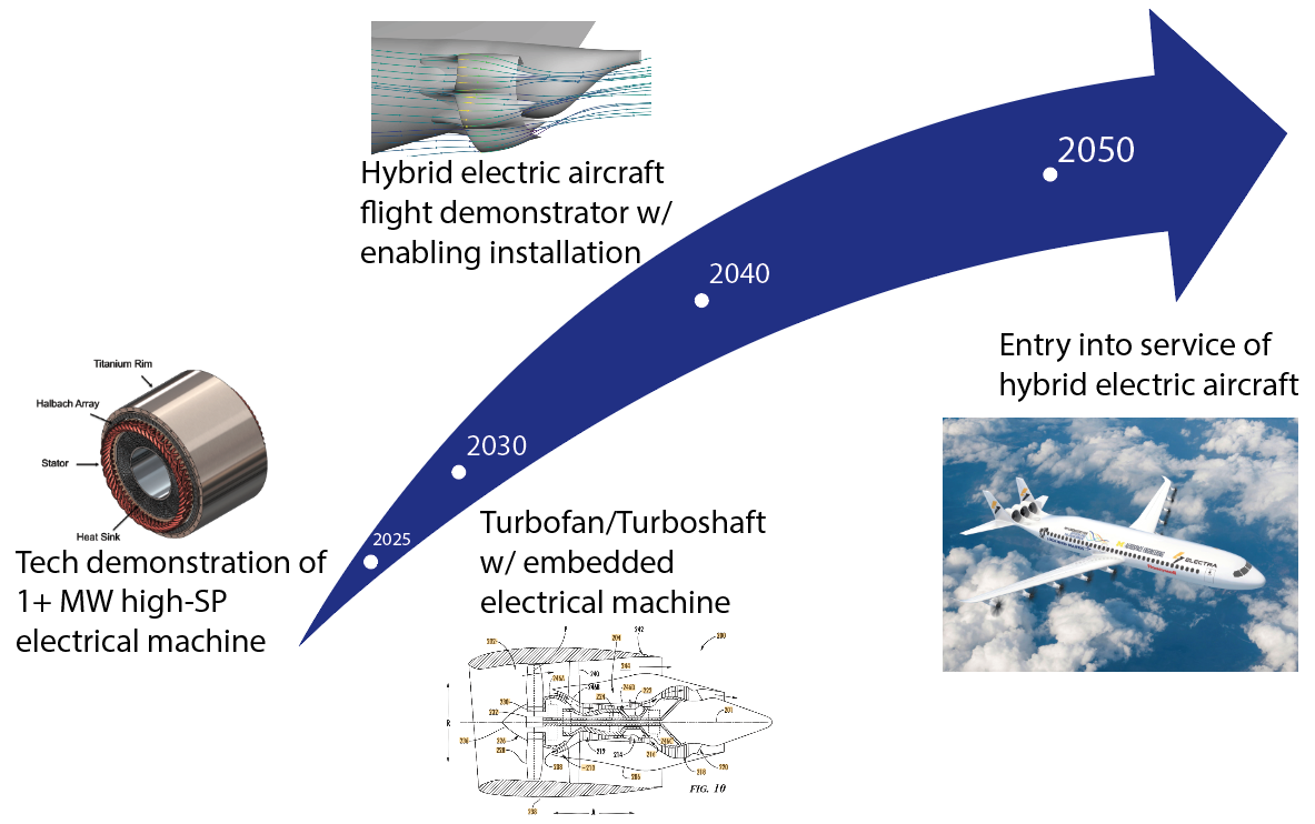
Integrated motor-generator technology is a critical pathway towards the goal of sustainable aviation. This goal is embodied by NASA's Advanced Aircraft Concepts for Environmental Sustainability (AACES) initiative [32], which aims to enter new sustainable aircraft into service by 2050. Close collaboration with NASA and the industry and academic partners working on this initiative is necessary to achieve this goal. To integrate electric motors and generators into new aircraft, a parallel approach should be taken which includes 1) investment in research and development of embedded electrical machine architectures, and 2) investment in novel propulsion-airframe integration technologies, such as distributed electric propulsion and boundary layer ingestion. Both of these investments will enable hybrid electric aircraft to be demonstrated by 2040 and entered into service by 2050.
1. Investment in research and development of embedded electrical machine architectures
As of 2025, megawatt-class, high specific power electrical machines have been demonstrated, most notably by the University of Illinois [10,26] and MIT [11]. These demonstrators are a giant step towards the feasibility of electrified aircraft, as they exceed NASA's 2030 target for electrical machine specific power [12]. The next step is to invest in research on architectures that embed the electrical machine in a turbofan or turboshaft. This results in a more compact power generation system with lower weight.
2. Investment in novel propulsion-airframe integration technologies, such as distributed electric propulsion and boundary layer ingestion.
Although not within the immediate scope of this roadmap, novel propulsion-airframe integration technologies enable electric propulsion systems to have a net benefit on energy consumption. This is because they provide a direct improvement of propulsive efficiency, weight, or drag, therefore resulting in reduced energy consumption throughout the mission. On its own, integrated motors and generators do not provide these benefits. However, they are required in order to achieve new propulsion-airframe integration strategies.
¶ 12. Roadmap Maturity Assessment (optional)
¶ 13. References
[1] N. Fernando, M. Barnes, and O. Marjanovic, “Direct drive permanent magnet generator fed AC-DC active rectification and control for more-electric aircraft engines,” Electric Power Applications, IET, vol. 5, pp. 14–27, Feb. 2011, doi: 10.1049/iet-epa.2009.0280.
[2] A. P. Dowdle, “Design of a High Specific Power Electric Machine for Turboelectric Propulsion,” Thesis, Massachusetts Institute of Technology, 2022. Accessed: Sept. 28, 2025. [Online]. Available: https://dspace.mit.edu/handle/1721.1/148615
[3] “Electra Technology,” Electra.aero. Accessed: Oct. 03, 2025. [Online]. Available: https://www.electra.aero/technology
[4] J. L. Felder et al., “Updated Assessment of Turboelectric Boundary Layer Ingestion Propulsion Applied to a Single-Aisle Commercial Transport,” E-19660, Oct. 2022. Accessed: Oct. 03, 2025. [Online]. Available: https://ntrs.nasa.gov/citations/20210016661
[5] M. K. Bradley and C. K. Droney, “Subsonic Ultra Green Aircraft Research: Phase 2: Hybrid Electric Design Exploration - Volume 2,” NF1676L-21005, Apr. 2015. Accessed: Sept. 25, 2025. [Online]. Available: https://ntrs.nasa.gov/citations/20150017039
[6] “EASA.E.015 - Lange EA42 series engines.” Accessed: Sept. 28, 2025. [Online]. Available: https://www.easa.europa.eu/en/document-library/type-certificates/engine-cs-e/easae015-lange-ea42-series-engines
[7] “HVH250 Series Electric Motors.” Remy. [Online]. Available: https://www.evwest.com/support/remy250.pdf?srsltid=AfmBOooHJ1ayNNcXtqhmMKhWjUjnsbupXugoPm-THAn5Iz5N_7VprWaL
[8] S. Kuznetsov, “Machine design and configuration of a 7000 HP hybrid electric drive for naval ship propulsion,” in 2011 IEEE International Electric Machines & Drives Conference (IEMDC), May 2011, pp. 1625–1628. doi: 10.1109/IEMDC.2011.5994605.
[9] “Electric Flight,” Siemens. Accessed: Oct. 03, 2025. [Online]. Available: https://press.siemens.com/global/en/feature/electric-flight
[10] L. Gipson, “NASA Tests Machine to Power the Future of Aviation Propulsion,” NASA. Accessed: Nov. 14, 2025. [Online]. Available: https://www.nasa.gov/aeronautics/nasa-tests-machine-to-power-the-future-of-aviation-propulsion/
[11] Y. Chen, “Technology Demonstration of a Megawatt-Class Integrated Motor Drive for Aircraft Propulsion,” Thesis, Massachusetts Institute of Technology, 2023. Accessed: Sept. 28, 2025. [Online]. Available: https://dspace.mit.edu/handle/1721.1/154196
[12] J. Welstead et al., “Overview of the NASA STARC-ABL (Rev. B) Advanced Concept,” Mar. 22, 2017. Accessed: Oct. 28, 2025. [Online]. Available: https://ntrs.nasa.gov/citations/20170005612
[13] RTX, “RTX advances hybrid-electric propulsion demonstrator with 1 MW motor rated power milestone test,” RTX News Center, 19 June 2023. [Online]. Available: https://www.rtx.com/news/news-center/2023/06/19/rtx-advances-hybrid-electric-propulsion-demonstrator-with-1mw-motor-rated-power-m
[14] RTX, “Collins Aerospace pushes e-aviation technology to new heights with family of powerful PM motors & generators,” Magnetics Magazine, Jan. 2 2024. [Online]. Available: https://magneticsmag.com/collins-aerospace-pushes-e-aviation-technology-to-new-heights-with-family-of-powerful-pm-motors-generators
[15] Safran Group, “ENGINeUS™ Smart Electric Motors — Product Page,” Safran Group, accessed Oct. 28, 2025. [Online]. Available: https://www.safran-group.com/products-services/engineustm
[16] Honeywell International Inc., “1 Megawatt (MW) Power Generator—Brochure,” Honeywell Aerospace, N61-2229-000-001, Jun. 2020. [Online]. Available: https://prod-edam.honeywell.com/content/dam/honeywell-edam/aero/en-us/products/power-and-propulsion/electric-power/honeywell-1-megawatt-mw-turbogenerator/documents/hon-aero-n61-2229-000-000-1mw-generator-brochure-en.pdf?download=false
[17] K. R. Antcliff, M. D. Guynn, T. Marien, D. P. Wells, S. J. Schneider, and M. J. Tong, “Mission Analysis and Aircraft Sizing of a Hybrid-Electric Regional Aircraft,” in 54th AIAA Aerospace Sciences Meeting, in AIAA SciTech Forum. , American Institute of Aeronautics and Astronautics, 2016. doi: 10.2514/6.2016-1028.
[18] GreenAir Communications. “EPA issues endangerment finding that paves the way for aircraft GHG regulation in the US.” GreenAir Online, 25 Jul. 2016. [Online]. Available: https://www.greenairnews.com/?p=6001.
[19] “UAL—Capital Expenditures (CAPX) Growth Rates,” CSIMarket. Available: https://www.csimarket.com/stocks/single_growth_rates.php?capx&code=UAL
[20] E. H. Davison and M. C. Stalla. Turboprop-engine design considerations 2: design requirements and performance of turboprop engines with a single-spool high-pressure-ratio compressor. NACA Research Memorandum NACA-RM-E55B18, Lewis Flight Propulsion Lab., National Advisory Committee for Aeronautics (now NASA), May 23, 1955. (Accession No. 19930088712) [Online]. Available: https://ntrs.nasa.gov/api/citations/19930088712/downloads/19930088712.pdf.
[21] United Airlines Holdings Inc., “Form 10-K for the year ended December 31, 2023,” U.S. Securities and Exchange Commission, EDGAR Document No. 0000100517-24-000027. Available: https://www.sec.gov/Archives/edgar/data/100517/000010051724000027/ual-20231231.htm
[22] United Airlines Holdings, Inc.. “Quarterly Report on Form 10-Q for the Quarterly Period Ended September 30, 2024.” United Airlines Holdings, Inc., Oct. 2024. [Online]. Available: https://www.sec.gov/Archives/edgar/data/319687/000010051724000136/ual-20240930.htm.
[23] B. Ewing. “Approaching 1000 Aircraft! United Airlines’ Fleet in 2024.” SimpleFlying, 3 Mar. 2024. [Online]. Available: https://simpleflying.com/the-united-airlines-fleet-in-2024/.
[24] M. Jacobson, “Record-setting 1MW ring motor,” Aerospace Manufacturing and Design. Accessed: Nov. 14, 2025. [Online]. Available: https://www.aerospacemanufacturinganddesign.com/article/record-setting-1mw-ring-motor/
[25] R. Dyson, “Current Status and Future Plans for Electric Motors and Drives at NASA,” 2021 IEEE International Electric Motors and Drives Conference, May 17, 2021.
[26] A. Yoon, Xuan Yi, J. Martin, Yuanshan Chen, and K. Haran, “A high-speed, high-frequency, air-core PM machine for aircraft application,” in 2016 IEEE Power and Energy Conference at Illinois (PECI), Urbana, IL, USA: IEEE, Feb. 2016, pp. 1–4. doi: 10.1109/PECI.2016.7459221.
[27] R. H. Jansen et al., “High Efficiency Megawatt Motor Preliminary Design,” presented at the AIAA/IEEE Electric Aircraft Technologies Symposium (EATS), Reston, VA, United States, Aug. 2019. Accessed: Nov. 14, 2025. [Online]. Available: https://ntrs.nasa.gov/citations/20190029589
[28] R. H. Jansen et al., “Subsonic Single Aft Engine (SUSAN) Transport Aircraft Concept and Trade Space Exploration,” presented at the 2022 SciTech Forum, San Diego, California. Accessed: Dec. 01, 2025. [Online]. Available: https://ntrs.nasa.gov/citations/20210025324
[29] Kupiszewski, T.; Miller, B. W.; Niergarth, D. A.; Vondrell, R. M., “Embedded electric machine”, U.S. Patent 10,308,366 B2, 4 June 2019.
[30] Lighty, K. J., “Gas turbine engine with embedded generator,” U.S. Patent 11,661,856 B2, May 30 2023.
[31] Fefermann, Y.; Reigner, P-A. J. P.; Naneix, P.; Delbosc, P., “System for converting and transporting electrical energy for the internal hybridisation of an aircraft turbomachine,” U.S. Patent 12378933 B2, 5 Aug. 2025.
[32] R. Margetta, “NASA Funds New Studies Looking at Future of Sustainable Aircraft.” Accessed: Nov. 17, 2025. [Online]. Available: https://www.nasa.gov/directorates/armd/nasa-funds-new-studies-looking-at-future-of-sustainable-aircraft/