¶ Two-Stage Cryogenic Cooler
This is the technology roadmap for “3TCC: Two-Stage Cryogenic Cooler” used in quantum computing. This technology falls under the Transforming–Energy (1E) section of the 5x5 technology matrix. This is a level 3 roadmap, indicating it is a subsystem of the Quantum Computer (level 1) Environmental Control System (level 2).
A quick introduction to the present roadmap is provided by the following video, also available on YouTube:
VIDEO Introductory video of the Two-Stage Cryogenic Cooler roadmap.
¶ 1. Roadmap Overview
Cryogenic cooling systems support a broad spectrum of applications, with the selection of a specific cryocooler driven by the performance needs of the host system. Across industry, eight primary cryocooler types are in routine use. Distinct patterns have emerged: Gifford–McMahon (GM) coolers dominate healthcare settings such as MRI systems, Stirling engines are widely adopted in defense for infrared sensing, and mixed-refrigerant coolers enable large-scale industrial processes including LNG production. In research environments, closed-loop helium-isotope systems have become increasingly prominent due to their enhanced reliability, operational stability, and substantially reduced maintenance requirements.
Within this broader cryogenic landscape, the dilution refrigerator (DR) remains the benchmark technology for reaching millikelvin temperatures. Early DRs relied on immersion in liquid-helium baths for precooling, a configuration that imposed significant operational complexity and consumable costs. The introduction of the pulse-tube cryocooler in the 1980s—and its subsequent integration with DRs in the early 2000s—enabled the transition to modern “dry” systems. This multistage architecture, referred to in this roadmap as the two-stage cryocooler system (3TCC) and comprising a pulse-tube precooler coupled to a dilution refrigerator is illustrated in Figure 1.1, and has since become the preferred platform for quantum technologies [47].
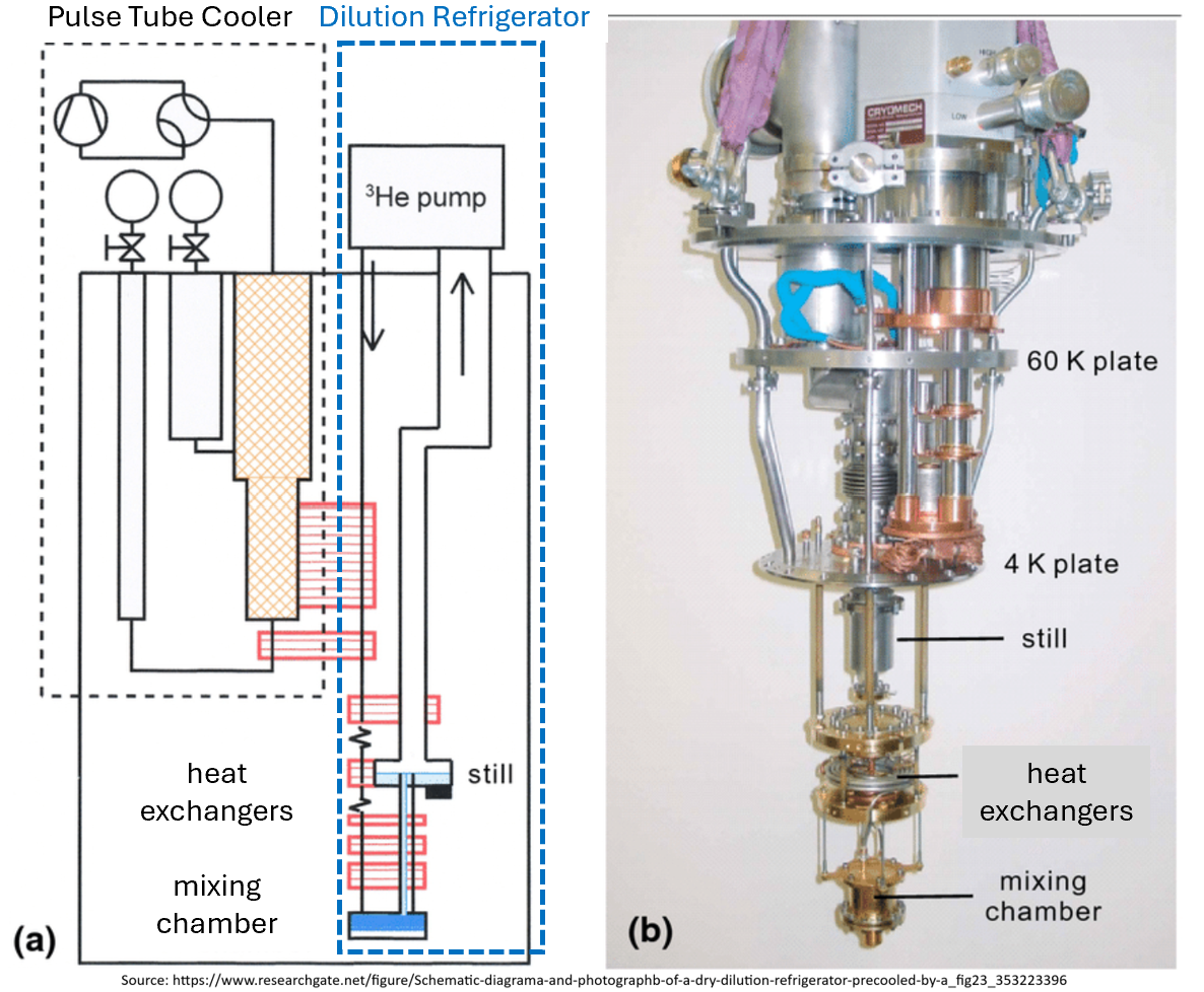
FIGURE 1.1 System diagram (a) and a picture (b) of a Two-Stage Cryogenic Cooler (modified from [36]).
The historical progression of dilution refrigerators, from their initial conceptualization in the 1950s to commercial maturity in the 1960s, and later to their integration with pulse-tube precoolers, demonstrates a consistent trajectory toward lower achievable temperatures, greater operational reliability, and reduced system complexity [46]. Today, the two-stage cryocooler system embodies both a sustaining and an enabling technology: sustaining in that it advances cryogenic performance beyond the limits of earlier helium-based approaches, and enabling in that it provides the essential thermal environment required for quantum-computing hardware [47].
The significance of this technology arises from its central role in quantum information processing, where qubit processors must be isolated from environmental noise to maintain coherence [34]. Thermal conduction paths managed through the pulse tube and into the dilution r efrigerator, combined with electromagnetic shielding and vibration isolation measures, establish the quiet operating environment required for reliable quantum computation. Conventional computing components in the overall system still rely on standard cooling approaches, but the two-stage cryocooler uniquely enables qubit operation at performance levels that cannot be achieved through any other thermal architecture.
This roadmap traces the evolution, adoption, and future trajectory of two-stage cryocoolers for quantum technologies. Key figures of merit, specifically minimum achievable temperature, percent Carnot efficiency, and cooling power, are used to align system capabilities with emerging application requirements.
¶ 2. Design Structure Matrix (DSM)
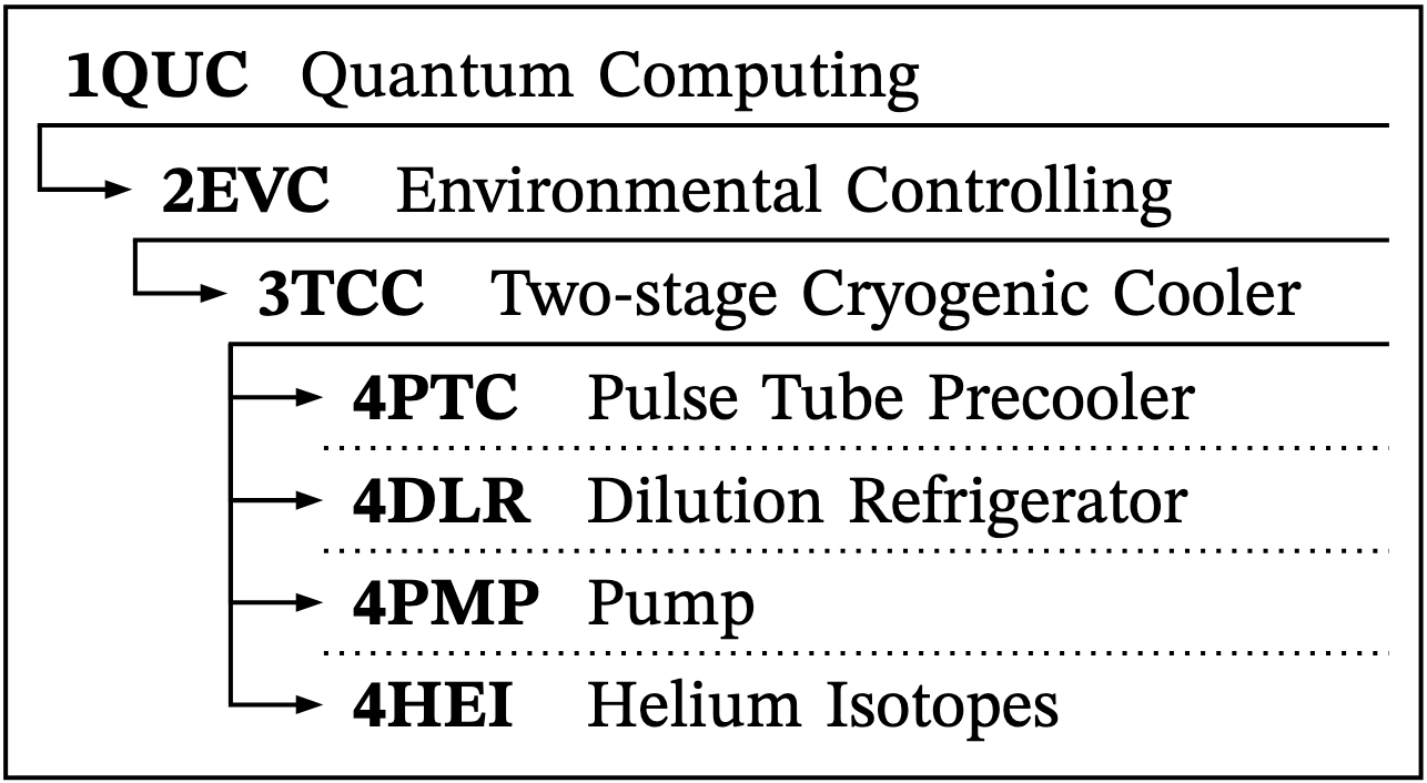
FIGURE 2.1 System Hierarchy and Nomenclature
This roadmap uses the acronym 3TCC to denote the multistage closed-loop cryocooler formed by the combination of the pulse tube cryocooler and the dilution refrigerator.
This system is interdependent with the roadmap 1QCAIML, and shares the common SD level of 1QUC, a roadmap for general quantum computing that has not yet been developed (see Figure 2.1 for the decomposition hierarchy). This interdependency will not be directly represented in our DSM but is considered part of the SD Level 1 Software Stack. The interdependencies are linked to the quantum computer itself and the challenges this technology faces due to environmental noise. This 3TCC is an enabling system for 1QUC and 1QCAIML.
SD |
SD1 |
SD2 |
SD3 |
SD4 |
|||||||||||||||||||||||||||
|---|---|---|---|---|---|---|---|---|---|---|---|---|---|---|---|---|---|---|---|---|---|---|---|---|---|---|---|---|---|---|---|
Quantum Computer |
Environmental Control System |
Thermal Control System |
Pulse Tube Cryocooler |
Dilution Refrigerator |
Helium Isotopes |
||||||||||||||||||||||||||
Quantum Computing |
Qubit Platform/Processor |
Quantum Control Electronics |
Classical Computer & Error Correction |
Quantum Interconnects & I/O |
Software Stack |
Infrastructure & Power |
Environmental Control System |
Thermal Control System |
Vacuum System |
Electromagnetic Shielding System |
Vibration Isolation system |
Thermal Anchoring & Wiring System |
Monitoring & Feedback System |
Pulse Tube Cooler |
Dilution Refrigeration |
Helium Isotopes |
Pump |
Condenser |
Regenerator |
Pulse tube |
Heat Exchanger |
Valve |
Condenser |
Mixing Chamber |
Heat Exchangers |
Still |
Helium 3 |
Helium 4 |
|||
SD |
Quantum Computing |
||||||||||||||||||||||||||||||
SD1 |
Quantum Computer |
Qubit Platform/Processor |
|||||||||||||||||||||||||||||
Quantum Control Electronics |
|||||||||||||||||||||||||||||||
Classical Computer & Error Correction |
|||||||||||||||||||||||||||||||
Quantum Interconnects & I/O |
|||||||||||||||||||||||||||||||
Software Stack |
|||||||||||||||||||||||||||||||
Infrastructure & Power |
|||||||||||||||||||||||||||||||
Environmental Control System |
|||||||||||||||||||||||||||||||
SD2 |
Environmental Control System |
Thermal Control System |
|||||||||||||||||||||||||||||
Vacuum System |
|||||||||||||||||||||||||||||||
Electromagnetic Shielding System |
|||||||||||||||||||||||||||||||
Vibration Isolation system |
|||||||||||||||||||||||||||||||
Thermal Anchoring & Wiring System |
|||||||||||||||||||||||||||||||
Monitoring & Feedback System |
|||||||||||||||||||||||||||||||
SD3 |
Thermal Control System |
Pulse Tube Cooler |
|||||||||||||||||||||||||||||
Dilution Refrigeration |
|||||||||||||||||||||||||||||||
Helium Isotopes |
|||||||||||||||||||||||||||||||
Pump |
|||||||||||||||||||||||||||||||
SD4 |
Pulse Tube Cryocooler |
Condenser |
|||||||||||||||||||||||||||||
Regenerator |
|||||||||||||||||||||||||||||||
Pulse tube |
|||||||||||||||||||||||||||||||
Heat Exchanger |
|||||||||||||||||||||||||||||||
Valve |
|||||||||||||||||||||||||||||||
Dilution Refrigerator |
Condenser |
||||||||||||||||||||||||||||||
Mixing Chamber |
|||||||||||||||||||||||||||||||
Heat Exchangers |
|||||||||||||||||||||||||||||||
Still |
|||||||||||||||||||||||||||||||
Helium Isotopes |
Helium 3 |
||||||||||||||||||||||||||||||
Helium 4 |
|||||||||||||||||||||||||||||||
-
Direct Component
-
Phyisical Interaction
-
Cross Relation
¶ 3. Roadmap Model using OPM
The 4PTC and 4DR are part of the 3TCC of a 1QUC system. This is represented Figure 3.1 as the System Design (SD2) level Object-Process Model (OPM) diagram.
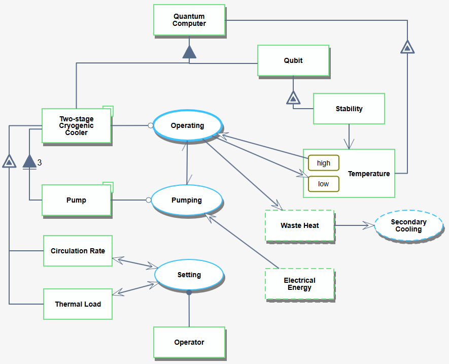
FIGURE 3.1 SD2: Interaction of the Two-stage Cryogenic Cooler (3TCC) within the context of the Environmental Control System of the Quantum Computer (1QUC)
Figure 3.2 and Figure 3.3 show the SD3 and SD4 levels of the quantum computing system, respectively. The former treats the pulse tube pre-cooler and the dilution refrigerator as a single unit, while the latter dives one level deeper to show the internal how the two subsystems.
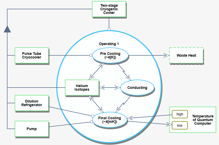
FIGURE 3.2 SD1: OPD showing the overview of the Thermal Control System and its inner working.
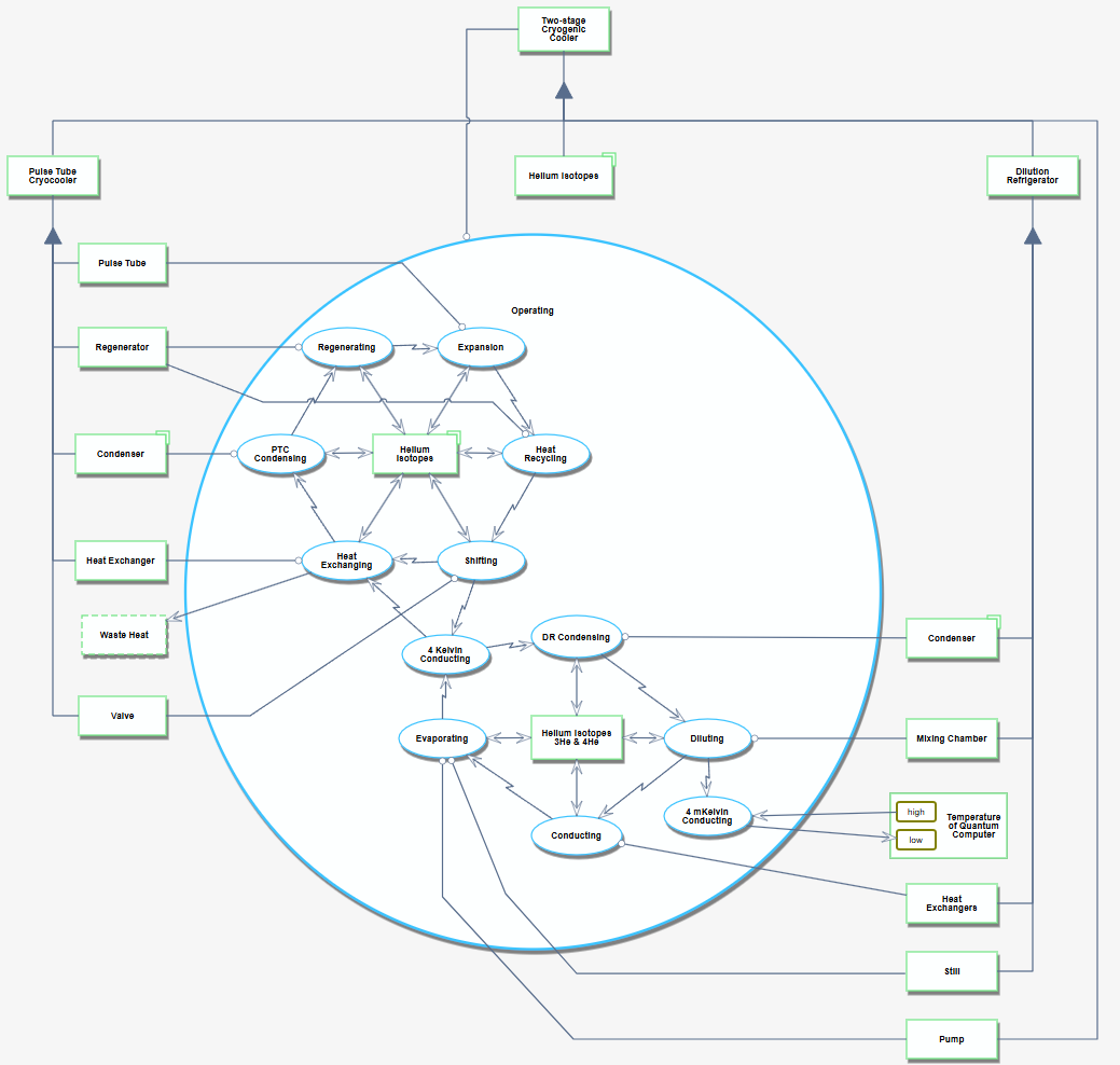
FIGURE 3.3 SD2: Components of the SD3 level
¶ 4. Figures of Merit (FOM)
¶ 4.1. Minimum Achievable Temperature
Lowest sustained temperature in the coldest stage (mixing chamber) that can be sustained under the specified load [25, p. 66]. Lower is better. Measured in .
|
Cooling power produced by 4DR, in . |
|
Molar flow of Helium isotopes, in . |
|
Minimum temperature at mixing chamber, in . |
|
Temperature going into mixing chamber from heat exchangers, in . |
|
Constant molar enthalpy difference at dilute at the mixing chamber, in . |
|
Constant molar enthalpy before entering the mixing chamber, in . |
¶ 4.2. Thermal Conductance
Thermal conductance is the transportation energy across matter and is a property of certain materials. This equation is the rate of heat flow per unit area resulting from a temperature gradient in a material cross section. Properties depending on material used and the required cooling power of the system, measured in [25, p. 62].
|
Required heat load for system, in . |
|
Area cross section of material, in . |
|
Thermal conductivity coefficient, in . |
|
Temperature gradient per unit area, in . |
¶ 4.3. Cooling Power
Net heat removed from the DR mixing chamber at a nominal temperature. Higher is better. This equation is to calculate the heat load required by the receiving system, in :
|
Heat load from system, in . |
|
Conduction heat load through supports, wiring, etc., in . |
|
Non-ideal contributions heat load, in . |
To calculate the cooling power produced by the system, in [25, p. 166]:
|
Molar flow of helium isotopes, in . |
|
Minimum temperature at mixing chamber, in . |
|
Constant molar enthalpy difference between dilute and concentrate phase in mixing chamber, in . |
Cooling power when the temperature into the mixing chamber does not equal the temperature in the mixing chamber (non-ideality), in [25, p. 165]:
|
Molar flow of helium isotopes, in . |
|
Minimum temperature at mixing chamber, in . |
|
Temperature going into mixing chamber from heat exchangers, in . |
|
Constant molar enthalpy difference at dilute at the mixing chamber, in . |
|
Constant molar enthalpy before entering the mixing chamber, in . |
¶ 4.4. Coefficient of Performance
Ratio of cooling power to input work; key measure of cryogenic efficiency. Higher is better. Unitless.
|
Input power to 3TCC, in . |
|
Cooling power produced by 3TCC, in . |
|
Power consumed by the pulse tube refrigerator, in . |
|
Power consumed by dilution refrigerator, in . |
|
Power consumed by ancillary equipment, in . |
¶ 4.5. Maximum Theoretical Efficiency
Maximum theoretical efficiency achievable by a perfect Carnot cycle. Higher is better. Unitless.
|
Temperature of the cold reservoir, in . |
|
Temperature of the hot reservoir, in . |
¶ 4.6. Percent Carnot Efficiency
Fraction of the ideal Carnot COP achieved by the real system. Indicates proximity to the theoretical limit given by . Also called second–law efficiency or exergy efficiency. It is calculated as the ratio of the actual work output to the maximum possible work output (exergy). Higher is better. Unitless (%).
|
The coefficient of performance, unitless. |
|
The maximum theoretical efficiency, unitless. |
¶ 4.7. Productivity
Operational cost per hour. Lower is better. Measured in .
|
Total costs including energy and maintenance, in . |
|
Total operating time, in . |
¶ 5. Alignment of Strategic Drivers
The following table outlines our strategic drivers and their alignment with this roadmap. As the table shows, the roadmap for dilution refrigeration technology aims to be an enabling technology that allows for the integration of quantum technology. Compared to our competitors, it is beneficial to be able to bridge the gap between modularity and performance, covering a wide array of customer sizes and needs.
# |
Strategic Driver |
Alignment and Targets |
|---|---|---|
1 |
To develop a continuous closed loop cooling system to achieve lower base temperatures and higher cooling power to below four millikelvin to support quantum technology research. |
The 3TCC roadmap is aligned to this strategic driver. With the supplement of a pulse tube precooler (4PTC), the system can achieve precooling temperatures of four kelvin, to allow cycling of helium down to reach as low as four millikelvin. |
2 |
To develop a dry cryogen-free system to reduce the cost of ownership and operational complexity through precooling, automation, and diagnostics. |
The 3TCC roadmap is aligned to this strategic driver. A pulse tube precooler eliminates the requirement for liquid helium baths. The closed loop system allows for lower cost due to higher efficiency and continuous operations and not limited by helium supplies due to constant reuse. |
3 |
To develop modular upgradable architectures that can support rapid change over time between experiments and long-term scalability as quantum hardware evolves. |
The 3TCC roadmap is aligned to this strategic driver. Through systems such as produced by Oxford instruments, dilution refrigeration systems can be scaled to support size of laboratory and match level of research. |
¶ 6. Positioning of Organization vs. Competition
Growth in quantum computing has directly increased demand for dilution refrigerators, creating a concentrated market dominated by two main organizations, Oxford Instruments and BLUEFORS. Both have industrialized and expanded their operations to support and lead this niche market. Their competition differs in strategic focus: BLUEFORS emphasizes lower base temperatures, scalability, and system lifetime support, while Oxford Instruments focuses on modularity through upgradable devices. Together, they form a technology-driven oligopoly where innovation is guided by quantum technology roadmaps, and premium pricing is maintained due to high barriers to entry. The industry’s high prices make it more difficult for smaller start-ups to enter, but they do not exclude other companies, such as Leiden Cryogenics BV, from participating on a smaller scale. The following table summarizes the various models offered by these three players, alongside their main properties.
Company |
Country |
Model |
Base Temperature |
Cooling power at 100 |
Diameter |
System Cooldown (From Room Temperature) |
|---|---|---|---|---|---|---|
BLUEFORS |
Finland |
SD |
30 mK |
250 µW |
148 mm (MXC flange) |
12 h |
BLUEFORS |
Finland |
LH250 |
< 10 mK |
> 250 µW |
294 mm (MXC flange) |
< 24 h |
BLUEFORS |
Finland |
LD250 |
10 mK |
250 µW |
294 mm (MXC flange) |
24 h |
BLUEFORS |
Finland |
LD400 |
10 mK |
400 µW |
294 mm (MXC flange) |
24 h |
BLUEFORS |
Finland |
LD400sl |
10 mK |
500 µW |
294 mm (MXC flange) |
22 h |
BLUEFORS |
Finland |
XLD400sl |
< 10 mK |
450 µW |
500 mm (MXC flange) |
23 h |
BLUEFORS |
Finland |
XLD1000sl |
10 mK |
> 1000 µW |
500 mm (MXC flange) |
29 h |
Oxford Instruments |
UK |
ProteoxS |
< 10 mK |
> 300 µW |
205 mm (sample space) |
20 h (without magnet) |
Oxford Instruments |
UK |
ProteoxMX |
< 10 mK |
> 450 µW |
360 mm (sample space) |
8 h |
Oxford Instruments |
UK |
ProteoxLX |
< 7 mK |
> 850 µW |
530 mm (sample space) |
6 h |
Oxford Instruments |
UK |
Proteox5mK |
5 mK |
> 850 µW |
360 mm (sample space) |
4 h |
Oxford Instruments |
UK |
KelvinoxTLM |
≤ 15 mK |
≥ 400 µW |
N/A |
12 h |
Leiden Cryogenics BV |
Netherlands |
CF-CS110-500 |
< 10 mK |
> 500 µW |
120 mm (sample space) |
8 h |
Leiden Cryogenics BV |
Netherlands |
CF-CS110-1000 |
< 8 mK |
> 1000 µW |
120 mm (sample space) |
8 h |
Leiden Cryogenics BV |
Netherlands |
CF-CS110-1500 |
< 7 mK |
> 1500 µW |
120 mm (sample space) |
8 h |
¶ 7. Technical Model: Sensitivities and Tradespace
To develop the technical model of the 3TCC, we selected two representative FOMs: the percent Carnot efficiency and the minimum achievable temperature.
The sensitivity analysis was performed by making partial derivatives of the identified FOM equations. For the sensitive parameters, normalization was applied to understand how a 1% difference in the parameters impacts the performance of the overall 3TCC. The key sensitive parameter values are summarized in a table format and are shown illustratively as tornado charts for each FOM.
¶ 7.1. Percent Carnot Efficiency
Combining elements from the FOMs presented in sections 4.3, 4.4, and 4.5, it is possible to model the 3TCC percent Carnot efficiency with the following equation:
For the purposes of the sensitivity analysis presented in this section, the following reference values from the literature are used:
Symbol |
Description |
Units |
Reference value(s) |
References |
|---|---|---|---|---|
|
molar flow rate through the DR loop |
|
|
[25, p. 182] |
|
Mixing chamber temperature |
|
|
|
|
Heat reject (ambient) temperature |
|
|
– |
|
Wall-plug electrical power |
|
|
[3] |
The sensitivity of each parameter is evaluated by first defining the partial derivative of with respect to the parameter itself, and then by evaluating the derivative at the reference design vector chosen from the values reported above.
The derivatives, sensitivities, and their normalized value are reported in the table below, while a graphical representation is shown in the tornado chart in Figure 7.1.
Param |
Derivative |
Ref. value |
Sensitivity |
Normalized |
|---|---|---|---|---|
|
|
|
|
|
|
|
1 |
2.52e-2 |
1 |
|
|
15 |
1.68e-3 |
1 |
|
|
300 |
8.4e-8 |
1 |
|
|
15 |
-1.68e-9 |
-1 |
The tornado chart for the Percent Carnot Efficiency shown in Figure 7.1 indicates that the efficiency is equally and linearly sensitive to each of its four parameters.The normalized sensitivities of ±1 arise because the efficiency is defined purely as a product or quotient of its parameters, meaning a proportional change in any parameter produces an equal fractional change in efficiency.
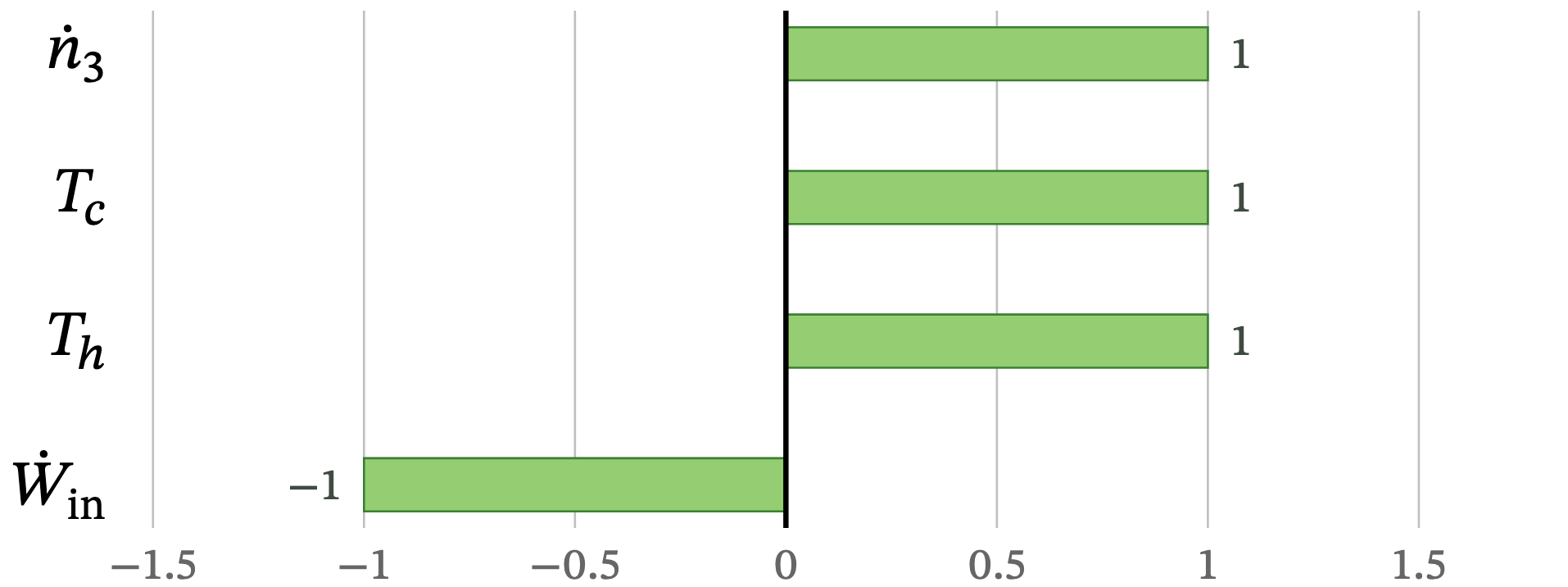
FIGURE 7.1 Tornado chart of the sensitivity of against each parameter composing its technical model.
In physical terms, this implies that system performance can be improved most effectively through reducing electrical input power or increasing cooling-loop flow rate and cold-end temperature control. However, because and are thermodynamically constrained, practical optimization typically focuses on compressor efficiency and circulation-loop design to minimize while maintaining the desired thermal gradient.
¶ 7.2. Minimum Achievable Temperature
Using the FOM equations referenced in section 4.1, the 3TCC minimum temperature is defined as:
This analysis is based on the following reference values from the literature:
Symbol |
Description |
Units |
Reference value(s) |
References |
|---|---|---|---|---|
|
Cooling power provided by the DR loop at |
|
|
|
|
molar flow rate through the DR loop |
|
|
[25, p. 182] |
|
Temperature of the liquid leaving the last heat exchanger and entering the mixing chamber |
|
|
[25, p. 166-167] |
As already presented in section 7.1, the derivatives, reference design vector , evaluated sensitivities, and their normalized value are reported in the table below, while a graphical representation is shown in the tornado chart in Figure 7.2.
Param |
Derivative |
Value |
Sensitivity |
Normalized |
|---|---|---|---|---|
|
|
|
|
|
|
|
420 |
1316 |
0.138 |
|
|
1 |
-0.552 |
-0.138 |
|
|
10 |
0.289 |
0.724 |
For the Minimum Achievable Temperature FOM, the tornado chart reveals asymmetric parameter influence: the exit-heat-exchanger temperature has the largest normalized sensitivity (+0.72), showing that even modest variations in strongly affect the lowest reachable temperature.
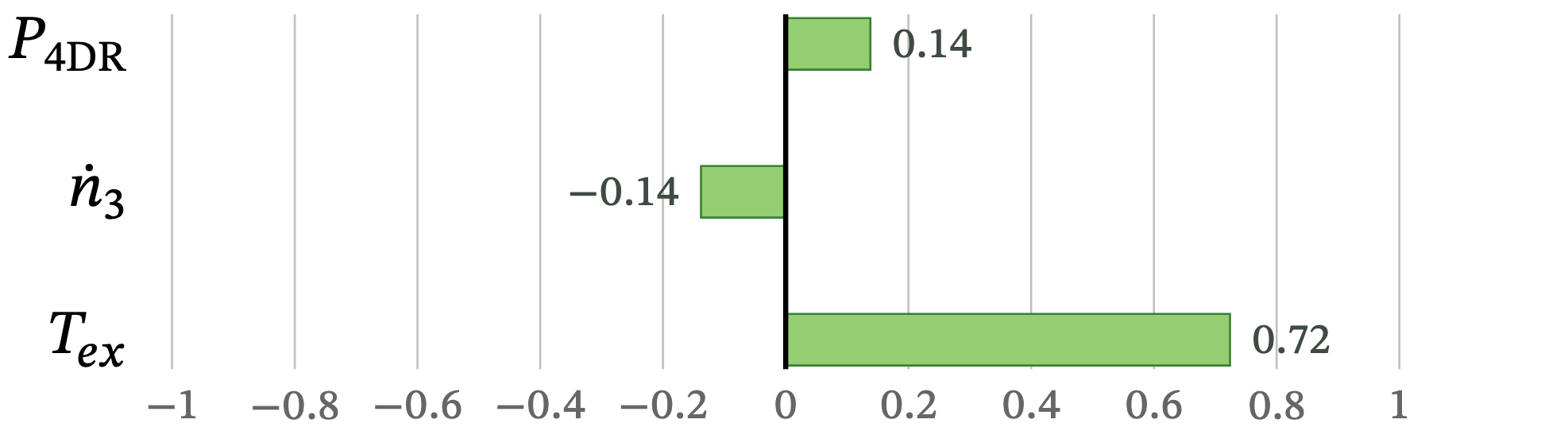
FIGURE 7.2 Tornado chart of the sensitivity of against each parameter composing its technical model.
The ³He flow rate and cooling-power terms exert weaker and opposite effects (−0.14 and +0.14, respectively), meaning that increasing the flow rate reduces while raising the cooling power increases it slightly. Design improvements should prioritize minimizing through physical optimizations (exchanger geometry, surface-area-to-flow-rate ratio, and material selection for better conductivity).
¶ 7.3. Tradespace
The tradespace shown in Figure 7.3 was created using the table in section 6. The x-axis is the cooling power at 100 mK (measured in µW), and the y-axis is the base temperature (measured in mK). Each of the dilution refrigerators annotated on the table is shown in the scatter plot below and labeled with its model number.
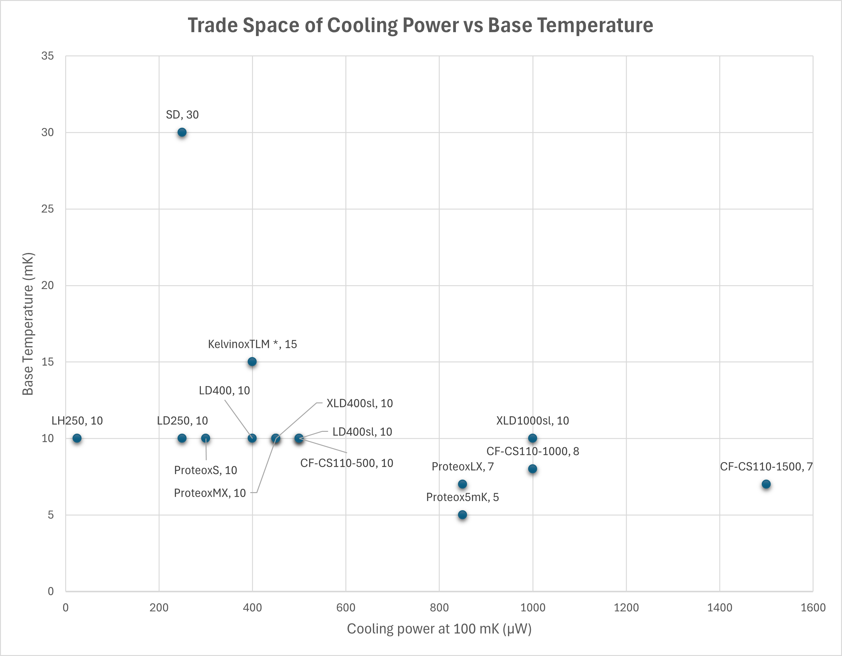
FIGURE 7.3 Tradespace of Coling Power vs. Base Temperature for various commercialized cryocoolers. Drawn based on data from [15].
¶ 8. Financial Model: Technology Value (𝛥NPV)
The figures below present a sample net present value analysis for the two-stage cryocooler (3TCC) over a 20-year period. The analysis below shows the lifecycle of a product development process from research and development to increasing production over time.
The assumptions for this analysis include an initial investment of $8 million for R&D over three years, with additional annual post-development costs of $190,000. Production was scheduled to start at year four, with a discount rate of 10%, a 90% learning rate, a production cost of $350,000 per unit, and a unit price of $800,000 per unit. Demand is calculated with an annual 3.5% increase to better reflect the slow start of a start-up company and support the expected 30% increase in dilution refrigeration utilization by 2035.
When comparing both free cash flow and discounted cash flow as shown in Figure 8.1, the product starts to show net positive earnings in year 12 and 15, respectively.
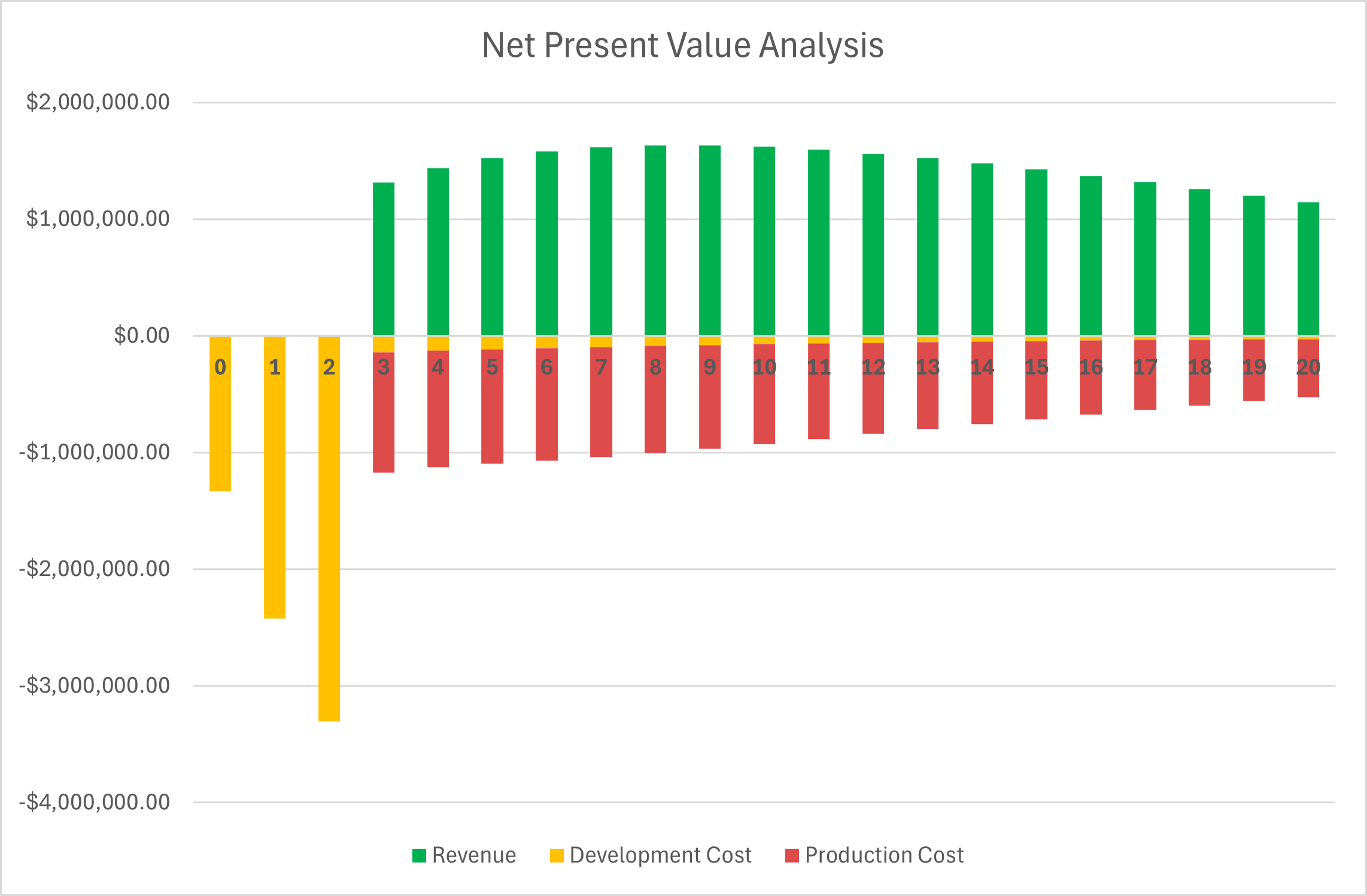
FIGURE 8.1 NPV Analysis.
After year 20, as shown in Figure 8.2, a positive net present value of $3.8 million is achieved, indicating that the project will deliver a positive return.
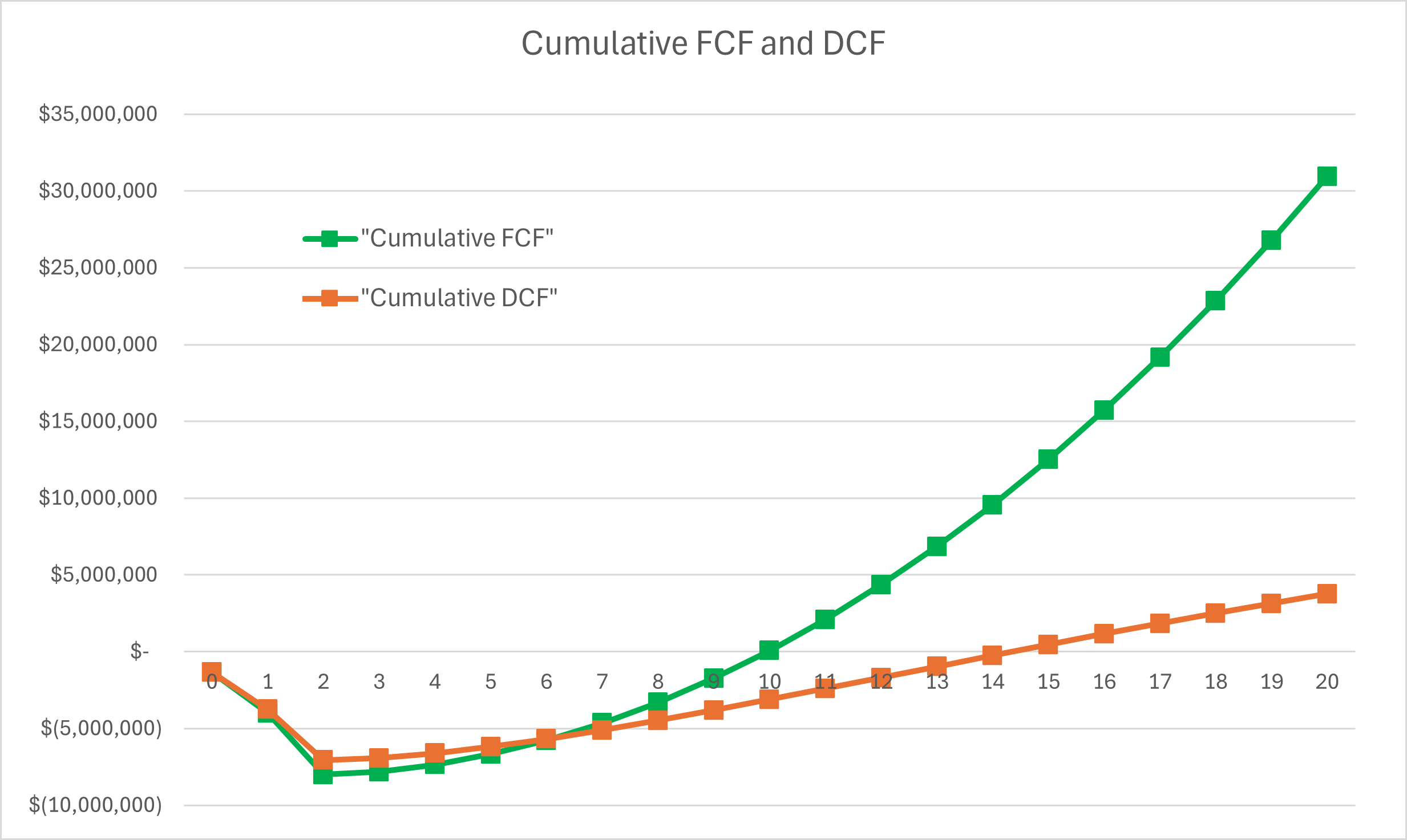
FIGURE 8.2 Free Cash Flow vs. Discounted Cash Flow.
¶ 9. List of R&D Projects and Prototypes
The goal of the selected R&D technologies is to understand the direction of development within the 3TCC using key FOMs. Due to the specialized nature of dilution refrigerators and sub-Kelvin cooling systems, most equipment is custom-engineered for specific quantum-computing or experimental requirements. As a result, it is difficult to directly compare different products under the same usage conditions or evaluate them with standardized financial metrics.
Given this limited transparency and lack of uniform benchmarks, the most meaningful insight comes from examining active R&D efforts that target the major technical bottlenecks in the 3TCC. The selected projects highlight advances in three critical limitation areas of scalability, helium-isotope scarcity, and thermal-load management through next-generation wiringand illustrate how industry and research institutions are addressing these constraints to support the increasing demands of quantum computing.
Limitation |
Description |
Current R&D Project |
Relevant FOMs |
|---|---|---|---|
Scalability |
Scalability is a critical R&D focus in quantum computing, since large-scale quantum processors require significantly more cooling power, wiring density, and thermal anchoring than conventional dilution refrigerators can support. Leading industry players are developing ultra-large, multi-PTC dilution refrigerators specifically to handle the thermal and mechanical demands of thousands-to-millions of qubits. |
IBM’s “Goldeneye” is an experimental, non-commercial dilution refrigerator designed by IBM to test the feasibility of scaling cryogenic infrastructure for future fault-tolerant quantum computers. The system is 1.5 meters in diameter and uses multiple pulse-tube cryocoolers to achieve a stable base temperature of ~25 mK across a very large volume [19]. |
Productivity, COE, Cooling power |
Scarcity of Helium Isotopes |
The long-term scalability of dilution refrigeration is constrained by the global shortage of helium isotopes, especially helium-3 (³He). ³He is extremely rare in nature and is produced almost exclusively as a byproduct of tritium decay in nuclear weapons programs and certain research reactors. As a result, global supply is limited, expensive, and politically sensitive, while demand from quantum computing and similar fields continues to rise. Helium-4 (⁴He), while naturally occurring, is also supply-constrained; commercial production depends heavily on extraction from a small number of natural-gas fields, making the supply chain vulnerable to geopolitical disruptions. This scarcity has driven a wave of R&D aimed at reducing ³He inventory, improving heat-exchanger efficiency, and developing alternative cryogenic technologies that either use less helium or eliminate helium isotopes entirely. |
Multiple cryogenics groups are developing low-charge dilution refrigerators, or similar equipment that significantly reduced ³He flow rates while maintaining usable cooling power for quantum technologies [15], [39]. |
Productivity, Cooling power |
Thermal Conductance |
Large-scale quantum processors require hundreds to thousands of microwave and control lines, each of which introduces unwanted heat into the dilution refrigerator. The thermal conductance of traditional coaxial wiring is now a primary scaling bottleneck for 3TCC systems usage in QC. As qubit counts increase, conventional metal coax cables overwhelm the cooling power at the 4 K, 1 K, and mK stages. |
Delft Circuits is currently producing the next generation flex-cable wiring system that significantly reduce thermal load per signal line while maintaining high-bandwidth performance. This enables much higher wiring density with substantially reduced conductive heat leakage into the 4 K, 1 K, and mK stages of dilution refrigerators. The company is continuing to develop their products to enable large scale wiring required for the demands of QC [37]. |
Thermal conductance, Cooling Power, Productivity |
¶ 10. Key Publications, Presentations and Patents
¶ 10.1. Publications & Presentations
Publication |
H. Zu, W. Dai, and A. de Waele, “Development of dilution refrigerators - A review,” Cryogenics, vol. 121, 2022. doi:10.1016/j.cryogenics.2021.103390 [47] |
|---|---|
Summary |
This review traces the technical and historical evolution of the ³He–⁴He Dilution Refrigerators (DRs). It highlights major design improvements like heat exchange optimization and the shift to “dry” DRs. This is also an important article because it reviews commercial and custom-built options as well as the common challenges of using DRs. |
Significance |
Comprehensive reference to the current state of DR technologies, its theoretical basis, and applications in current industry. This is a great reference article to check the current market DRs, how the DRs have evolved over time, and the basics of how the system works. |
Publication |
K. Uhlig, “Dry dilution refrigerator with pulse-tube precooling,” Cryogenics, vol. 44, pp. 53–57, 2004. doi: 10.1016/j.cryogenics.2003.07.007 [46] |
|---|---|
Summary |
This article reports the design and testing on a cryogen-free (“dry”) dilution refrigerator that uses a pulse-tube cryocooler (PTC) instead of a helium bath. This article goes over the results of testing and includes a summarization of the key advantages of this approach. |
Significance |
Demonstrates that a PTC precooling method paired with a DR can match the traditional helium bath systems while being more practical and economical. This advancement significantly brings down the maintenance and other drawbacks of the wet systems. This article set the foundation for today’s commercial “dry” cryocoolers. |
Publication |
K. Uhlig, “3He/4He dilution refrigerator with pulse-tube refrigerator precooling,” Cryogenics, vol. 42, pp. 73–77, 2002. doi: S0011-2275(02)00002-4 [45] |
|---|---|
Summary |
Describes first-generation version of the DR precooled by a two-stage PTC, achieving a final temperature of 15 mK. This combines a counterflow heat exchanger with a Joule-Thomson expansion stage for condensation of the ³He–⁴He mixture. This model also demonstrates an automated cooldown, stable operation, and minimal vibrations. |
Significance |
Represents one of the first successful integrations of PTCs with DRs, proving that cryogen-free systems can reach the milliKelvin range. This was a large jump in the current market for cryocoolers and their cumbersome maintenance and upkeep requirements. |
¶ 10.2. Patents
Patent |
P. Gunmann, S. B. Olivadese, and J. M. Chow, “Thermalization of cryogenic quantum circuits,” U.S. Patent 10833240B2, Nov. 10, 2020 [8] |
|---|---|
Summary |
Focuses on efficient thermal anchoring and wiring for superconducting qubit systems within dilution refrigerators. It optimizes heat transfer between microwave lines and cold stages while suppressing vibration and electromagnetic noise. |
Significance |
Connects dilution-refrigerator engineering to practical quantum-computing thermal management. |
CPC Codes |
|
Patent |
G. Batey, P. G. Teleberg, A. Matthews, et al., “Cryogenic cooling apparatus and method,” U.S. Patent 9816750B2, Nov. 14, 2017 [24] |
|---|---|
Summary |
Describes a cryogen-free (“dry”) DR using a mechanical PTC and an automated sample loading system. This patent covers a more durable, faster, and safer system. |
Significance |
Embodies modern, commercially deployed cryogen-free dilution technology used in quantum-computing cryostats. |
CPC Codes |
|
Patent |
R. C. Black, J. P. Hilton, G. Rose, et al., “Systems, methods, and apparatus for cryogenic refrigeration,” U.S. Patent 20100281885A1, Nov. 11, 2010 [38] |
|---|---|
Summary |
Describes a cryogenic refrigeration system that integrates a PTC with a DR, specifically using the PTC as a pre-component to feed the DR via ³He-⁴He isotopes. This patent specifies the step-down multiple cooling stages from PTC to DR to the DR’s mixing chamber. Specifically cites the use in superconducting computer systems. |
Significance |
This patent was an innovation milestone of the dry dilution refrigerator in the industry. It was also a strategic submission for use of this specific system for the quantum-computing horizon. |
CPC Codes |
|
Patent |
F. A. Staas and A. P. Severijns, “3He/4he dilution refrigerator,” U.S. Patent 4136531A, Jan. 30, 1979 [1] |
|---|---|
Summary |
Introduces a dual-mixing chamber ³He–⁴He DR, achieving lower base temperatures by circulating ³He through a “superleak”. |
Significance |
Foundation of intellectual property for the continuous ³He–⁴He DR systems still used in low-temperature physics and quantum device cooling today. |
CPC Codes |
|
¶ 11. Technology Strategy Statement
With dilution refrigerators being the key enabling technology for quantum computing research, it is imperative to develop and scale to support the growing demand. The market is expected to experience a 25-fold increase in demand; therefore, research and development must capitalize on this added demand.
As of 2022, IBM is currently prototyping its proof-of-concept prototype of the Goldeneye Super Fridge. This dilution refrigerator is expected to be the largest, with a volume of 1.7 cubic meters, and is capable of achieving successful operating temperatures of ~25 mK. Project completion is expected beyond 2025. We estimate deployment will not occur until 2028.
Delft Circuits is currently producing the next-generation flex-cable wiring system, which significantly reduces the thermal load per signal line while maintaining high-bandwidth performance. This enables much higher wiring density with substantially reduced conductive heat leakage into the 4 K, 1 K, and mK stages of dilution refrigerators. The company is continuing to develop its products to meet the large-scale wiring requirements of QC demands.
With ³He being the key isotope utilized for dilution refrigerator use, scalability will be limited, causing extensive measures to acquire resources. This will require improving the efficiency of current systems over time. By 2045, it is reasonable to see efficiency advancements as a priority, which will likely be scalability to meet demands in quantum computing.
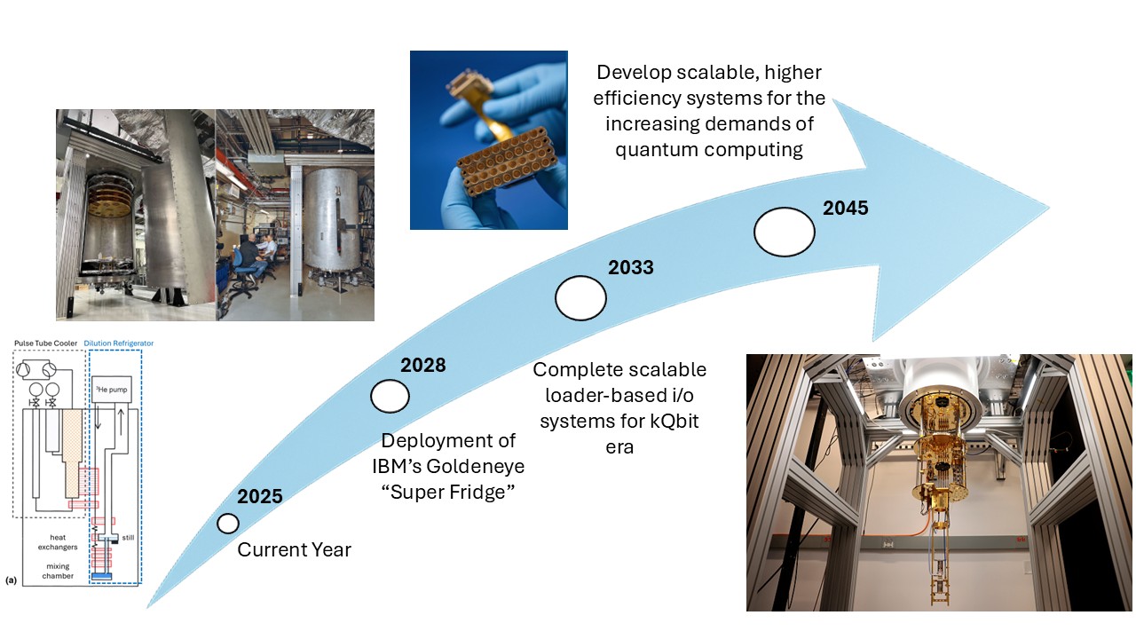
FIGURE 11.1 Technology Strategic “Swoosh Chart”.
¶ 12. References
- Staas, F. A. and Severijns, A. P. 3He/4He dilution refrigerator. January 1979. URL: https://patents.google.com/patent/US4136531A/en.
- Duval, J.-M. Adiabatic Demagnetization Refrigerators. October 2019. URL: https://indico.cern.ch/event/792215/contributions/3409445/attachments/1919353/3181090/2019-10-03-ADR-EASI-Duval-v3.pdf (visited on 2025-10-05).
- Arute, F., Arya, K., Babbush, R., Bacon, D., Bardin, J. C., Barends, R., Biswas, R., Boixo, S., Brandao, F. G. S. L., Buell, D. A., Burkett, B., Chen, Y., Chen, Z., Chiaro, B., Collins, R., Courtney, W., Dunsworth, A., Farhi, E., Foxen, B., Fowler, A., Gidney, C., Giustina, M., Graff, R., Guerin, K., Habegger, S., Harrigan, M. P., Hartmann, M. J., Ho, A., Hoffmann, M., Huang, T., Humble, T. S., Isakov, S. V., Jeffrey, E., Jiang, Z., Kafri, D., Kechedzhi, K., Kelly, J., Klimov, P. V., Knysh, S., Korotkov, A., Kostritsa, F., Landhuis, D., Lindmark, M., Lucero, E., Lyakh, D., Mandrà, S., McClean, J. R., McEwen, M., Megrant, A., Mi, X., Michielsen, K., Mohseni, M., Mutus, J., Naaman, O., Neeley, M., Neill, C., Niu, M. Y., Ostby, E., Petukhov, A., Platt, J. C., Quintana, C., Rieffel, E. G., Roushan, P., Rubin, N. C., Sank, D., Satzinger, K. J., Smelyanskiy, V., Sung, K. J., Trevithick, M. D., Vainsencher, A., Villalonga, B., White, T., Yao, Z. J., Yeh, P., Zalcman, A., Neven, H., and Martinis, J. M. Quantum supremacy using a programmable superconducting processor. Nature, 574(7779):505–510, October 2019. doi:10.1038/s41586-019-1666-5.
- Uhlig, K., Weisend, J. G., Barclay, J., Breon, S., Demko, J., DiPirro, M., Kelley, J. P., Kittel, P., Klebaner, A., Zeller, A., Zagarola, M., Van Sciver, S., Rowe, A., Pfotenhauer, J., Peterson, T., and Lock, J. Dry Dilution Refrigerator with High Cooling Power. In AIP Conference Proceedings, volume 985, 1287–1291. Chattanooga (Tennessee), 2008. AIP. doi:10.1063/1.2908485.
- De Waele, A. T. A. M. Basic Operation of Cryocoolers and Related Thermal Machines. Journal of Low Temperature Physics, 164(5-6):179–236, September 2011. doi:10.1007/s10909-011-0373-x.
- Bluefors and Oxford Instruments: A statement. URL: https://bluefors.com/press-releases/bluefors-and-oxford-instruments-a-statement/ (visited on 2025-10-28).
- Pradhan, J., Das, N. Kr., and Chakraborty, A. Thermo-dynamical process simulation of dilution refrigerator. Cryogenics, 57:158–165, October 2013. doi:10.1016/j.cryogenics.2013.07.003.
- Gunmann, P., Olivadese, S. B., and Chow, J. M. Thermalization of cryogenic quantum circuits. November 2020. URL: https://patents.google.com/patent/US10833240B2/en.
- Radebaugh, R. Development of the Pulse Tube Refrigerator as an Efficient and Reliable Cryocooler (1999). Proc. Institute of Refrigeration, 96:11–29, 1999–2000.
- DICEEASIFIT. URL: https://www.iceoxford.com/supD-supICEsupEASIFIT-sup.htm (visited on 2025-10-28).
- Wielens, D. Dilution refrigerators. August 2022. URL: https://indico.global/event/6729/contributions/55605/attachments/28035/48530/ECC2022_Wielens_DilutionRefrigerators.pdf (visited on 2025-10-05).
- Uhlig, K. Dry dilution refrigerator with 4He-1 K-loop. Cryogenics, 66:6–12, March 2015. doi:10.1016/j.cryogenics.2014.10.004.
- DRYICE EDEN Brochure 2. URL: https://www.iceoxford.com/files/image/files/DRYICE%20EDEN%20Brochure%202.pdf (visited on 2025-10-28).
- prouvé, T., Godfrin, H., Gianese, C., Triqueneaux, S., and Ravex, A. Pulse-Tube Dilution Refrigeration below 10 mK for Astrophysics. Journal of Low Temperature Physics, 151:640–644, May 2008. doi:10.1007/s10909-008-9725-6.
- ICV TA&K. Global Dilution Refrigerator Report 2025. 2025. URL: https://icvtank.oss-ap-southeast-1.aliyuncs.com/QUANTUM-REPORTS/ICV-Global%20Dilution%20Refrigerator%20Report%202025-Mar.%2021%2C%202025.pdf.
- Google. Our Quantum Computing Roadmap. 2025. URL: https://quantumai.google/roadmap (visited on 2025-10-26).
- Cousins, D. J., Fisher, S. N., Guénault, A. M., Haley, R. P., Miller, I. E., Pickett, G. R., Plenderleith, G. N., Skyba, P., Thibault, P. Y. A., and Ward, M. G. An Advanced Dilution Refrigerator Designed for the New Lancaster Microkelvin Facility. Journal of Low Temperature Physics, 114(5):547–570, March 1999. doi:10.1023/A:1021862406629.
- Radebaugh, R. Historical Summary of Cryogenic Activity Prior to 1950. In Timmerhaus, K. D. and Reed, R. P., editors, Cryogenic Engineering, pages 3–27. Springer New York, New York, NY, 2007. doi:10.1007/0-387-46896-X_1.
- IBM cools down world's largest quantum-ready cryostat. September 2022. URL: https://www.ibm.com/quantum/blog/goldeneye-cryogenic-concept-system (visited on 2025-10-28).
- IBM Quantum. 2025 Development & Innovation Roadmap. 2025. URL: https://www.ibm.com/downloads/documents/us-en/131cf87ab63319bf.
- In-Depth Industry Outlook: Cryogen Free Dilution Refrigerators Market Size, Forecast. URL: https://www.verifiedmarketresearch.com/product/cryogen-free-dilution-refrigerators-market/ (visited on 2025-10-27).
- Lawson, C. R., Jones, A. T., Kockelmann, W., Horney, S. J., and Kirichek, O. Neutron imaging of an operational dilution refrigerator. Scientific Reports, 12(1):1130, January 2022. doi:10.1038/s41598-022-05025-0.
- Tanaeva, I. A., De Waele, A. T. A. M., Lindemann, U., Jiang, N., and Thummes, G. The superfluid vortex cooler. Journal of Applied Physics, 98(3):034911, August 2005. doi:10.1063/1.2001730.
- Batey, G., Teleberg, P. G., Matthews, A., and Wilkinson, C. Cryogenic cooling apparatus and method. November 2017. URL: https://patents.google.com/patent/US9816750B2/en.
- Pobell, F. Matter and Methods at Low Temperatures. Springer, Berlin, 3rd rev. and expanded ed. edition, 2007. ISBN 978-3-540-46356-6.
- University, A. Microkelvin investigations (µKI). January 2024. URL: https://www.aalto.fi/en/department-of-applied-physics/microkelvin-investigations-mki (visited on 2025-10-05).
- Microsoft Quantum. Quantum Roadmap. 2025. URL: https://quantum.microsoft.com/en-us/vision/quantum-roadmap (visited on 2025-10-26).
- Bandgar, A. Orifice Pulse Tube Refrigerator. International Journal for Research in Applied Science and Engineering Technology, 12(11):2016–2027, November 2024. doi:10.22214/ijraset.2024.65543.
- Oxford Instruments and Bluefors: a statement. URL: https://www.oxinst.com/news/oxford-instruments-and-bluefors-a-statement/ (visited on 2025-10-28).
- Batey, G. and Teleberg, G. Principles of Dilution Refrigeration. Oxford Instruments NanoScience, 2015.
- ProteoxS - Nanoscience - Oxford Instruments. URL: https://nanoscience.oxinst.com/products/proteoxs (visited on 2025-10-27).
- IBM Technology Atlas. IBM QC Roadmap. April 2025. URL: https://www.ibm.com/roadmaps/quantum/ (visited on 2025-10-28).
- Liu, Z., Ma, Y., Quan, J., Liu, Y., Wang, J., Li, J., and Liang, J. Development of a compact 2.17 K hybrid 4He JT cryocooler for space applications. Cryogenics, 118:103347, September 2021. doi:10.1016/j.cryogenics.2021.103347.
- NIST. In Quantum Sensing, What Beats Beating Noise? Meeting Noise Halfway. September 2025. URL: https://www.nist.gov/news-events/news/2025/09/quantum-sensing-what-beats-beating-noise-meeting-noise-halfway (visited on 2025-12-01).
- Aalto University. Record low temperatures. January 2024. URL: https://www.aalto.fi/en/otanano/record-low-temperatures (visited on 2025-10-05).
- Cao, H. Refrigeration Below 1 Kelvin. Journal of Low Temperature Physics, September 2021. doi:10.1007/s10909-021-02606-7.
- Delft Circuits. Roadmap. URL: https://delft-circuits.com/team/roadmap/ (visited on 2025-12-01).
- Black, R. C., Hilton, J. P., Rose, G., Petroff, J. C., and Uchaykin, S. V. Systems, methods, and apparatus for cryogenic refrigeration. November 2010. URL: https://patents.google.com/patent/US20140137571A1/en.
- Kim, P. H., Hirschel, M., Suranyi, J., and Davis, J. P. Continuously cooled 3He-4He phase-separation refrigerator. Physical Review Applied, 24(1):014042, July 2025. doi:10.1103/6mjc-zz6z.
- de Weck, O. L. Technology Roadmapping and Development: A Quantitative Approach to the Management of Technology. Springer International Publishing, 2022. ISBN 978-3-030-88345-4. doi:10.1007/978-3-030-88346-1.
- Total System Care - Bluefors.com. URL: https://bluefors.com/services/total-system-care/ (visited on 2025-10-27).
- Total System Care. March 2023. URL: https://bluefors.com/services/total-system-care/ (visited on 2025-10-28).
- Oxford Instruments. Triton™ XL. URL: https://nanoscience.oxinst.cn/assets/uploads/TritonXL_Brochure_Feb2018_1.pdf (visited on 2025-10-28).
- Unland, K. Zero Point Cryogenics closes deal involving National Research Council. September 2022. URL: https://edmonton.taproot.news/news/2022/09/23/zero-point-cryogenics-closes-deal-with-national-research-council (visited on 2025-10-27).
- Uhlig, K. 3he/4he dilution refrigerator with pulse-tube refrigerator precooling. Cryogenics, 42:73–77, 2002. doi:S0011-2275(02)00002-4.
- Uhlig, K. Dry dilution refrigerator with pulse-tube precooling. Cryogenics, 44:53–57, 2004. doi:10.1016/j.cryogenics.2003.07.007.
- Zu, H., Dai, W., and de Waele, A. Development of dilution refrigerators - A review. Cryogenics, 2022. doi:10.1016/j.cryogenics.2021.103390.
Statement on the Use of AI
AI, specifically OpenAI’s ChatGPT (GPT-5 model), was employed during the preparation of this document as a support tool for research organization, verification, and editorial consistency. Google’s NotebookLLM was used to create the introductory video using this roadmap and the credited sources.
In addition, ChatGPT was used to improve clarity, coherence, and grammatical accuracy across sections. Whenever ChatGPT returned references, those have been vetted for quality and applicability before having been used in the present document.
All conceptual reasoning, modeling assumptions, and analytical interpretations were developed and validated independently by the authors, who assume full responsibility for the accuracy and integrity of the submitted work.