Space electric propulsion
Roadmap creators: Marc Rizk Danyel deSa
Time stamp: December 5, 2023
Roadmap Overview
Spacecraft electric propulsion uses electrostatic or electromagnetic fields to accelerate mass to high speed and thus generate thrust to modify the velocity of a spacecraft in orbit. This method leverages the charge/mass ratio of propellants, with relatively small potential differences potentially generating high exhaust velocities. This reduces the amount of reaction mass or propellant required, but increases the amount of specific power required compared to chemical rockets. Electric propulsion systems fall into three broad categories - electrothermal, electromagnetic, and electrostatic.
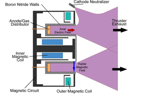
We have a schematic diagram of a Hall thruster above. The working principle of the Hall thruster is that it uses an electrostatic potential to accelerate ions up to high speeds. In a Hall thruster, the attractive negative charge is provided by an electron plasma at the open end of the thruster. A radial magnetic field (typically about 10–30 mT) is used to confine the electrons, where the combination of the radial magnetic field and axial electric field cause the electrons to drift in azimuth thus forming the Hall current from which the device gets its name.
The propellant (such as xenon gas) is fed through the anode, which has numerous small holes in it to act as a gas distributor. As the neutral xenon atoms diffuse into the channel of the thruster, they are ionized by collisions with circulating high-energy electrons. Most of the xenon atoms are ionized to a net charge of +1, but a noticeable fraction (sometimes close to 20%) have +2 net charge.
The xenon ions are then accelerated by the electric field between the anode and the cathode. For discharge voltages of 300 V, the ions reach speeds of around 15 km/s (9.3 mi/s) for a specific impulse of 1,500 s. Upon exiting, however, the ions pull an equal number of electrons with them, creating a plasma plume with no net charge.
Electric thrusters typically use much less propellant than chemical rockets because they operate at a higher specific impulse than chemical rockets. Due to limited electric power the thrust is much weaker compared to chemical rockets, but electric propulsion can provide thrust for a longer time.
Several space companies are actively incorporating electric propulsion in their spacecraft, showcasing advancements in propulsion technologies. NASA, the United States' space agency, has been a prominent player in this arena, employing ion propulsion in missions such as Dawn, which explored the asteroids Vesta and Ceres. Additionally, Airbus, a major aerospace manufacturer, has been at the forefront of developing and implementing electric propulsion systems for satellites and spacecraft. Boeing, another leading aerospace company, has explored electric propulsion technologies for communication satellites. Notably, SpaceX, founded by Elon Musk, is also contributing to the use of electric propulsion. While SpaceX is widely known for its reusable rocket technology, the company has shown interest in developing and deploying advanced propulsion systems, including electric propulsion, to enhance the efficiency and capabilities of its spacecraft. As the space industry continues to evolve, these companies play pivotal roles in shaping the future of space exploration and satellite deployment through innovative propulsion technologies.
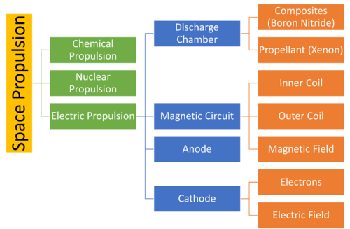
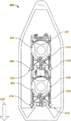
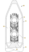
Below we see the overview of our roadmap with key components outlined.
Design Structure Matrix (DSM) Allocation
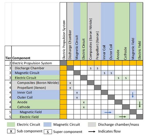
Our DSM Allocation for electric propulsion is based on a Hall thruster (as described above) with sub components classified by tier and colour. Cells shaded in grey indicate matter (such as the composites that make up the walls of the discharge chamber, and propellant). Cells shaded in blue and green represent items corresponding to the magnetic and electric circuits, respectively.
Roadmap Model using OPM
We have our Object Process Diagram (OPD) for the 2SEP roadmap below. This strives to capture the various categories of electric propulsion, key components in a typical (Hall thruster) system, and finally sub-components and how they relate to relevant Figures of Merit (FOMs). Key activities include flying (travelling) and recharging.
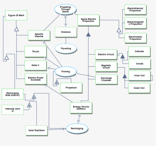
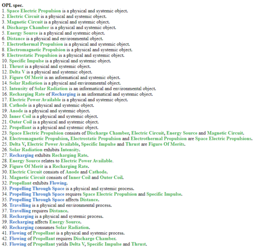
An Object Process Language (OPL) description for 2SEP can be found below. This translates the OPD into a natural language.
Figures of Merit
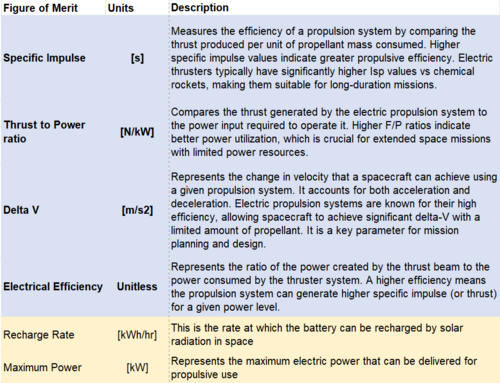
Relevant figures of merit can be seen in the table below. The metrics highlighted in blue are likely determined by the type of mission that the propulsion system is to be used for. Metrics highlighted in yellow are largely independent of mission in our view.
We believe it is also instructive to analyze the equations that govern electric propulsion in space. We have the following relations between specific impulse (Isp), thrust (F), steady state velocity (V), thruster electric efficiency (n), electrical power fed into the thruster (Pe), standard acceleration due to gravity on the earth's surface (g0), and the rate at which propellant is discharged (dm/dt).
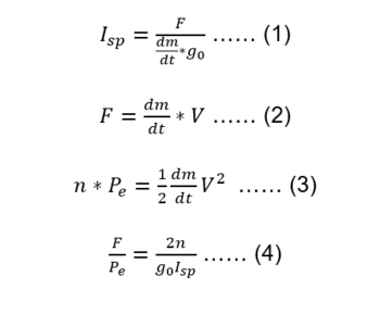
We use equations (1), (2), and (3) to derive equation (4). The result is of great significance - we see that the product of the thrust to power ratio (F/P) and specific impulse (Isp) is constant, and directly proportional to the electrical efficiency (n) of the thruster. This tradeoff is key to determining the choice of thruster and propellant:
- For deep space missions, the requirement is typically for high specific impulse to maximize thrust that can be achieved over the life of the mission with a given quantity of propellant. This comes at the expense of thrust-to-power however, or the thrust that can be achieved with a given power input.
- For station keeping or use with satellites in LEO or GEO, typically the requirement is for a higher thrust-to-power ratio, and this comes at the expense of specific impulse (a high mass of propellant is needed to produce the same thrust).
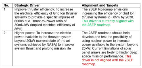
Strategic Drivers
The key strategic drivers are electrical efficiency of the thruster system, and input power available to the thruster. These directly relate to increasing the product of specific impulse and thrust-to-power, which we know to be directly proportional to thruster efficiency. This is to say that increasing thrust efficiency pushes out the pareto frontier and will enable a more diverse range of space missions with longer lives. Additionally, increasing power available to the system will result in higher output thrust available.
Comparison with Competitors and FOMs
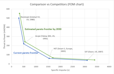
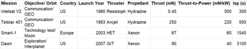
Given that thruster parameters vary widely by mission purpose and orbit, we consider 'competitors' to be rival space missions. For station keeping applications, we assume that our company is trying to improve on the Telstar 401 mission launched by the US in 1993. Similarly, for deep space missions, we would aim to build upon the progress achieved by the Dawn mission launched by NASA in 2007.
We look at the FOMs of Thrust-to-Power versus Specific Impulse to compare ourselves to our competitors. As can be seen, we have chosen to compare four electric propulsion technologies that were used to power four missions - Resistojet, Arcjet, Hall Effect, and Grid Ion. For each of these technologies, we have selected missions that have achieved results that are closest to the Pareto frontier (i.e. with the highest product of Thrust-to-Power and specific impulse).
With regards to improvement in FOMs, we have assumed that our 2030 target is to see a 10% improvement for both parameters. This is in line with historical improvements in thruster efficiency, which is around 20% per decade (10% improvement in each parameter gives us an efficiency improvement of 21%). This will help us visualize how the Pareto front is likely to move with time - there are scenarios where we may want to trade off Thrust-to-Power for a higher specific impulse, and vice versa. This will likely be determined by the scope of mission, type of thruster chosen, and choice of propellant.
Technical Model and Morphological Tradespace
The key to trading off parameters is having a technical model that allows us to understand how different metrics are related. We can leverage the equations described in the Figure of Merit section above - the product of thrust-to-power and electrical efficiency is approximately constant, and we must thus trade one parameter for another. This is depicted elegantly in the figure below, courtesy of Holste, K. et al.
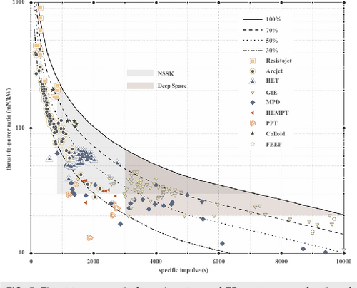
We see how deep space missions seek thrusters with high specific impulses to maximize the thrust that can be extracted from a given quantity of propellant, and station keeping missions typically use thrusters that can deliver high thrust-to-power ratios. This is the key tradeoff when deciding what type of electric propulsion system to use for a given mission.
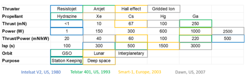
Below, we see how these parameters were traded off for actual space missions in the past in a morphological tradespace.
Key Publications and Patents
Key Publications:
1. Igor Levchenko, Dan M. Goebel, Kateryna Bazaka; Electric propulsion of spacecraft. Physics Today 1 September 2022; 75 (9): 38–44. https://doi.org/10.1063/PT.3.5081
- The publication covers a few key topics:
- Improved stability and control: The authors explore how electric propulsion can enhance the stability and control of spacecraft – particularly for cubesats and satellite constellations that require thrust with precision. Hydrazine thrusters and cold gas systems do not have the level of specific impulse and control needed for these missions.
- Barriers to adoption: The authors identify and discuss the challenges to the widespread adoption of electric propulsion in spacecraft – the lack of sufficient electric power on spacecraft, the ability to store sufficient energy, and thruster lifetime.
- Electric thrusters in deep space: The publication explores applications of electric thrusters in deep space missions. The authors mention NASA’s Dawn mission, which was the first deep-space mission that used electric propulsion to reach and orbit two bodies in the asteroid belt—Vesta and Ceres. The spacecraft’s gridded ion thrusters used 400 kg of xenon to accomplish the mission. Chemical thrusters would have required more than 6 tons of additional fuel.
- Overall, the authors present a comprehensive overview of the current state and future potential of electric propulsion technology for spacecraft.
2. Gabriel F. Benavides, Hani Kamhawi, Timothy R. Sarver-Verhey, Corey R. Rhodes, Matthew J. Baird, and Jonathan A. Mackey; High-propellant throughput Sub-kW electric propulsion system for Deep Space Science and exploration - NASA technical reports server (NTRS). NASA. https://ntrs.nasa.gov/citations/20220009248
- This paper entails the development of high-propellant throughput sub-kW electric propulsion technologies to enable deep space science and exploration missions with high delta-v requirements, for small spacecraft.
- The pathfinder model (PM) propulsion system consists of the H71M-PM HET, a breadboard 1-kW power processing unit (PPU), and a propellant flow control system. The propulsion system provides stable thrust generation over a wide range of operating conditions from 200 W to 1 kW, and 200 V to 400 V. The thruster has demonstrated a thrust as high as 68 mN at 300 V and 1 kW, and a specific impulse of 1850 s at 400 V and 1 kW.
- Short duration wear tests indicate that a target thruster lifetime of 14 kh with 50% margin is feasible, though further verification of this result is needed.
Patents: A summary of recent patent activity involving electric propulsion is summarized below.
A. Methods and apparatus for performing propulsion operations using electric propulsion systems (US20200331638A1) – filed by Boeing Co:
- Markets: US
- Filed: 6/16/2020
- Granted: 7/25/2023
- This patent looks at a novel method and apparatus for performing propulsion using an electric propulsion system. An example launch vehicle includes a first space vehicle with a certain core structure and electric propulsion system, and a second space vehicle with a second core structure and a second electric propulsion system. The key insight is that the second core structure is releasably attached to the first space vehicle in a stacked configuration.
B. Multiple space vehicle launch system (US9394065B2) – filed by Boeing Co:
- Markets: US, EP, CN
- Filed: 9/15/2014
- Granted: 7/19/2016
- Here, the authors have filed a patent for a vehicle launch system that includes a first space vehicle including a first core structure and a second space vehicle including a second core structure. The second core structure is oriented relative to the first space vehicle such that when placed within a fairing, a launch load is transmitted from the first core structure of the first space vehicle and is borne by the second core structure of the second space vehicle, thereby eliminating the need for a dual-launch structure or other reinforcing or support structures. The first space vehicle and the second space vehicle each include respective electric propulsion units.
C. Spacecraft propulsion system and method (RU2684968C2) – filed by Frederic Marchandiz:
- Markets: FR, EP, RU, JP, CN, WO
- Filed: 7/27/2015
- Granted: 4/16/2019
- This invention involves the use of a space propulsion system that comprises an electrostatic thruster and a resistojet thruster; a circuit to supply propellant fluid and a circuit for supplying electricity. The system also comprises a switch for connecting the electricity supply line to resistojet and electrostatic thruster. This method for propulsion in space includes a switching step to select the first driving mode in which the resistojet thruster is activated, or the second driving mode in which electrostatic thruster is activated.
Financial Model
We develop a model based on estimates of the size of the satellite equipment market and utilize Aerospace Corporations “Development of the Small Satellite Cost Model” as a proxy for the value of propulsion systems within the cost of a satellite. We believe satellites represent the best way to measure the incremental NPV for this technology, given that the number of satellites in LEO/GEO is rapidly growing and there is a steady cadence of growth in the satellite market (as opposed to deep space missions which are more idiosyncratic). Given that what we are largely talking about is incremental innovation, our approach is to create a notional P&L and cash flow for a propulsion equipment company to calculate the value of this market. As such, the R&D costs are implicit within the operating margin we assume.
According to Market reports, for example Spherical Insights, the Satellite Communications Equipment Market was c$22bn in size in 2022 and growing at a CAGR of 9.5% over the next 10 years. In order to derive the size of the propulsion component of the market we are looking at, we rely on Aerospace Corporations cost model which breaks down the key cost components of the satellites. According to their cost models, Propulsion represents some 8% of the input cost of a satellite.
As the two areas we are focused on, Hall Effect Thrusters and Gridded Ion Engines, represent c80-85% of the market, we take the addressable satellite market for our technologies to be c$18 bn. As our 8% figure is related to input cost, we assume 50% gross margins for the satellite companies which implies an overall input cost base of $9 bn (implicitly, the cost of purchasing the components of the satellite, including propulsion systems, from suppliers). From this (and the 8% contribution to the cost of a satellite of Propulsion Systems), we estimate the overall electric space propulsion market to be c $720m in size and assume it will grow at a slightly higher CAGR of 10% based on the greater adoption of the technologies we are looking at. In addition, we believe that the cost component of Propulsion, given technological development, is likely to increase and we assume that its proportion of the cost will rise to 10% over the next 10 years.
As there is very limited information on the margins of stand-alone propulsion companies, we make an assumption of 15% EBITDA margins and derive an NPV based on a discount rate of 12%.
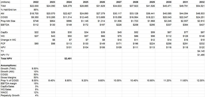
As we can see from the above model, the NPV for the electric propulsion (on satellites) market is just under $2.5bn, with much of its value coming from the industry's high growth rate. Assuming we are able to capture even 10% market share, this would represent a value of ~$250Mn
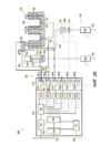
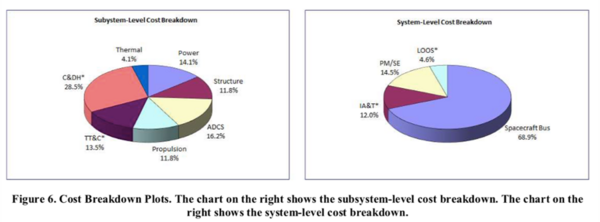
Estimate Drivers:
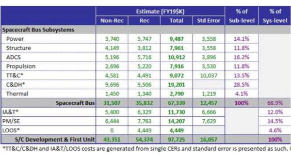
In the figure above, the section to the left includes details on the estimate for the spacecraft generated by the CERs including non-recurring/recurring costs, total costs, and percentage distributions at the subsystem-level and system-level. The section to the right highlights inputs that are out of the valid range of the CERs for each estimate (IA&T = Integration, Assembly, and Test; LOOS = Launch and Orbital Operations Support; PM/SE = Program Management/Systems Engineering).
In the above model, we have specifically looked at and modeled the market for electric propulsion on satellites. While this is currently the greatest use case for the technology, experts predict other industries/markets emerging in the coming years which may add more value to this type of technology. Two notable ones which we have discussed in the R&D section are nano/micro SATs as well as space tugs (which is pegged to be a $65bn industry in the coming 20 years).
Future Projects and R&D
Space electric propulsion systems include a wide variety of thrusters and operate using complex processes. As such, the integration and optimization of thrusters is still an evolving field and one with a lot of scope for incremental innovation. This includes the development of new tools and instruments, novel plasma characterization systems and the design of novel, advanced space propulsion systems with excellent characteristics. Below, we identify some key areas of development, some immediate and others somewhat longer term.
Required on-going & future developments:
- Mini-ion engines system and microfield emission thrusters to satisfy the needs of future gravity missions and other science missions such as NGGM and LISA.
- Mini-hall thrusters system to satisfy the needs of future mini/micro-satellites to perform SK and disposal maneuvers in constellations.
- Micropropulsion for Nano satellites and micro satellites (NEWMARKET)
- Large Electric Propulsion Systems to meet the needs of future asteroid or planetary exploration missions. Cargo missions to Mars will also make good use of these systems.
Space Tugs: Electric propulsion is considered as one of the key technologies for Space Tugs due to the relatively low propellant consumption compared to chemical propulsion. The four most relevant applications include:
- GEO Servicing
- LEO/MEO Debris Removal (Mega constellations, SSO debris removal)
- LEO/MEO to GEO tugging (for telecommunication satellites, 60 kW tug would be required)
- Moon cargo delivery (high Isp operation would be of interest). A clear need has also been identified for the development of high power (~15 kW-20kW), long lifetime Hall effect thrusters for future Space Tugs.
In terms of specific R&D Projects, some key ones that can be identified include:
- Extension of the lifetime of Hall Effect Thrusters via magnetic confinement and double operation point (higher thrust during orbit raising and higher specific impulse during NSSK). This would benefit telecommunications, navigation and Science and Exploration missions. Power levels around 5 kW or higher.
- Reduction of the power to thrust ratio via the cusp design in Ion Engines. This would benefit telecommunications, navigation and Science and Exploration missions. Power levels around 5 kW or higher.
- Development of mini-ion engines, FEEPs and mini-Hall effect thrusters for use in science and Earth observation missions. Thrust levels from micro-Newtons to some milli-Newtons. Lifetime will be a special issue to be assessed. Constellations will use low power Hall Effect Thrusters.
- Testing facilities will require the utilization of High power engines. The standardization of testing methods will also be required to reduce cost and risk of these developments.
- More broadly, new High Power Electric Propulsion Concepts evaluation (Helicon Antenna Thruster, Electron Cyclotron Resonance thruster, MPD, E-Impact thruster, etc.) will be needed.
Technology Strategy Statement
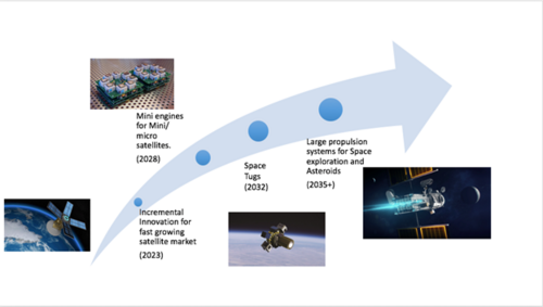
Our technology strategy statement would read as follows - "Despite being an established technology, incremental innovation in space propulsion systems are vitally needed for upcoming space missions, including Mars and Moon exploration and advanced outer space scientific missions."
Below we have provided a Swoosh chart for electric propulsion in space.