Difference between revisions of "Orbital Launch Vehicles Roadmap"
| Line 281: | Line 281: | ||
: <math> \frac{x_{i,0}}{J(X^0)}\frac{\partial r}{\partial \Phi}|_{x^0} = 0.003% </math> | : <math> \frac{x_{i,0}}{J(X^0)}\frac{\partial r}{\partial \Phi}|_{x^0} = 0.003% </math> | ||
[[File:Sensibility.png|500px]] | [[File:Sensibility.png|500px|thumb]] | ||
== Keys Publications and Patents == | == Keys Publications and Patents == | ||
Revision as of 02:59, 9 November 2019
Roadmap Overview
Orbital launch vehicles (LV) are internally propelled vehicles used to carry payloads from Earth’s surface to Earth orbit or beyond. They are powered by rocket engines that generate large amounts of thrust even in vacuum by means of expelling hot gas through a nozzle. The propellants burnt to generate that gas can be liquid or solid (or hybrids) and are stored inside the LV. Most launch vehicles are divided into stages to discard non-used structure and some of them are reusable.
This roadmap will be an L1 roadmap from the point of view of the LVs as a technology that enables the Human race to transport cargo from the surface of the Earth to outer space.
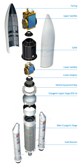
As an example, an Ariane 5 LV is typically used to insert up to 2 geostationary satellites into a GTO per launch. Its launch mass is about 777 metric tons and has a LEO capacity of about 20 tons and a GTO capacity of about 10 tons.
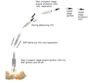
On a typical flight, the different stages of the OLV such as the first stage, the solid rocket boosters, and interstages will be jettisoned to reduce the mass of the vehicle until the payloads are precisely deployed at the desired orbit.
DSM Allocation
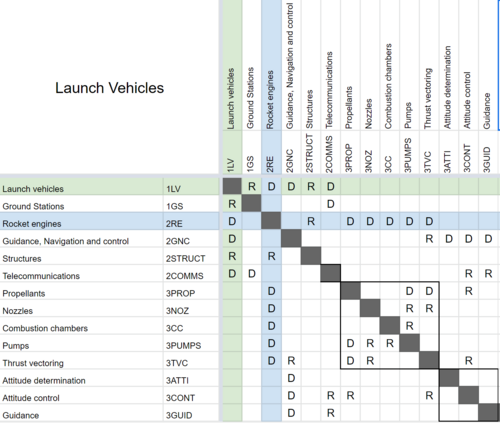
The following DSM shows the relationship of the Launch Vehicles roadmap to other high or lower level roadmaps.
The following tree structure can be also extracted from it:
- 1LV Launch vehicles
- 2RE Rocket engines
- 3PROP Propellants
- 3NOZ Nozzles
- 3CC Combustion chambers
- 3PUMPS Pumps
- 3TVC Thrust vectoring
- 2GNC Guidance, Navigation and control
- 3ATTI Attitude determination
- 3CONT Attitude control
- 3GUID Guidance
- 2STRUCT Structures
- 2COMMS Telecommunications
- 2RE Rocket engines
- 1GS Ground Stations
Roadmap model using OPM
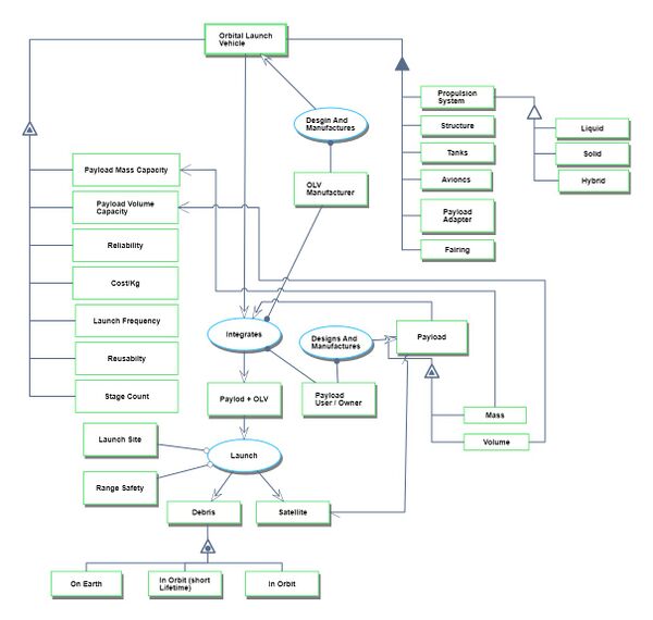
The following Object Process Diagram describes the Orbital Launch Vehicle technology point of view for this roadmap. The main object of the diagram is the different launch vehicles, its decomposition into main components/subsystems like propulsion system, structures, tanks, avionics, payload adapters, and the main attributes. Finally, the processes in the lifecycle are described as the integration of the payloads and the actual launch.
Figures of merit
The table below shows a list of FOMs by which Orbital Launch Vehicles can be assessed.
| Figure of Merit | Units | Description |
|---|---|---|
| Payload to LEO | [Kg/Year] | Payload mass that can be put into a 500 Km circular low earth orbit for a specific launch vehicle every year. This takes into account the production rate of the rockets and, if applicable, the reusability. |
| Payload to mass Ratio | [Kg/Kg] | Mass capacity to LEO over total LVs mass (including the payload). |
| Reliability | [non-dimensional] | Successful launches over total launches. |
Cost per Kg as a FOM wasn't considered in this roadmap because of the difficulty of obtaining accurate data.
Physical principles
In order to put a payload in orbit, an OLV needs to accelerate to a certain velocity in a certain direction at a specific altitude from the center of the Earth. This requirement can be derived from Newton’s Universal Gravitational Law and can be approximated for circular orbits as:
Where G is the universal gravitational constant, M the mass of the Earth and r the distance to the center of the planet of the orbit. So for example, a 500km circular orbit around the Earth will require a velocity of approximately 7.61 km/s or 27405 Km/h. A few more km/s are usually needed to account for atmospheric losses and other non-idealities.
In other to achieve that velocity, OLV uses rockets engines that use a combination of fuel and oxidizers (known as propellants) to create a high-pressure gas that is then accelerated by a converging-diverging nozzle to create thrust.
- <math>\Delta v = v_\text{e} \ln \frac{m_0}{m_f} = I_\text{sp} g_0 \ln \frac{m_0}{m_f}</math>
Where ΔV is the change of velocity of the vehicle, m0 is the initial total mass, including propellant, also known as wet mass, mf is the final total mass without propellant, also known as dry mass, ve is the exhaust velocity and is equal to Isp times g0. Here, Isp is the specific impulse in the dimension of time and is a measure of effectively the rocket use the propellant and g0is standard gravity. In other words, this equation relates the total amount of velocity change that a rocket engine can create on a system by means of the initial and final mass (loss of mass of propellant), the efficiency. When multiple stages are present this equation must be considered for each stage.
So, as ΔV is known, then choosing a propulsion system will define the Isp and this will lead to the ratio of the initial and final mass necessary or which is equivalent to the amount of mass for structure tanks and engines, payload and propellant that is needed.
For example, this table shows some figures of merit of different rocket engines.
| OLV | Propellant % of total mass | Payload % of total mass |
|---|---|---|
| Saturn V | 85 | 4 |
| Space Shuttle | 85 | 1 |
| Soyuz | 91 | 2 |
In conclusion, the only FOM that is directly related to a physical principle is the Payload to mass Ratio described above.
Payload to mass Ratio [Kg/Kg]
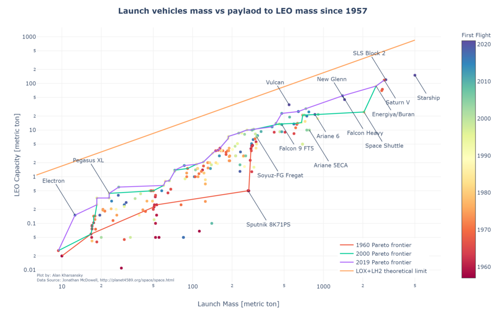
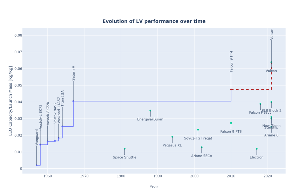
Useful payload to orbit is driven by the Rocket Equation and then affected by the different efficiency factors and non-idealities of the real Launch Vehicles designed and implementation. The trend in the payload to mass ratio is illustrated in the following plot using historical database <ref>McDowell's JSR Database (Links not working)</ref> since 1957. Only those LVs which has successfully achieved orbit at least once and carrying more than 10 Kg of payload were considered. A trend towards bigger LVs and more efficient can be observed.
Caveat: the LEO capacity figure is an approximation and is not normalized to a specific orbit across LVs. A substantial difference might be present if the stated LEO capacity was calculated for a 600 KM SSO orbit instead of a 400 Km equatorial orbit.
The evolution over time of this FOM can be seen in the following plot. In this case, only those LV that are better than the previous ones is plotted.
Payload to LEO [Kg/Year]
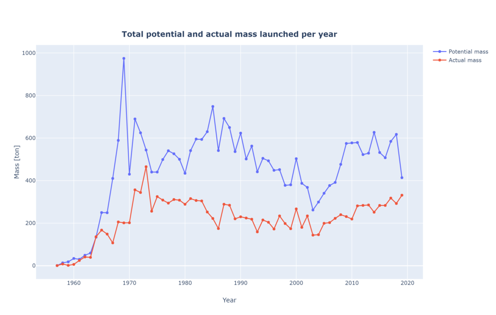
Payload to LEO can be used to estimate the capacity of the total launchers to put payload in orbit. In this case, two different sub-FOMs where calculated. First, the actual mass launched by aggregating all the masses of all the satellites on every launch per year. This doesn't include the payload adapters and dispensers used for the launch. On the other hand, the potential capacity is the sum of the total LEO capacity for each vehicle aggregated every year. As a reference, the ISS is about 419 tons and the James Webb Space Telescope is approximately 6.2 tons.
Reliability
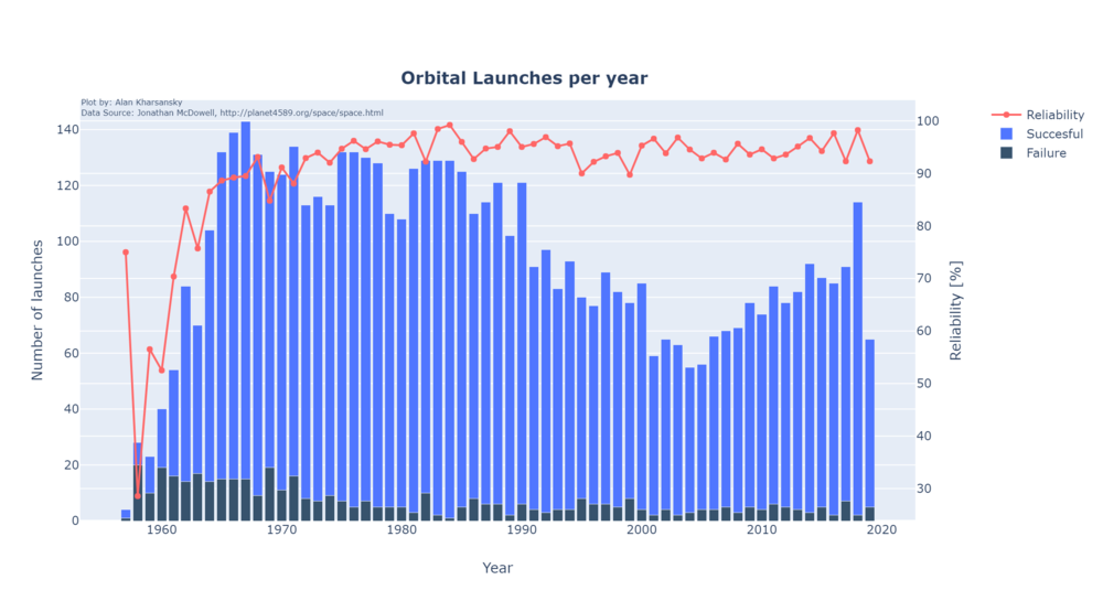
The reliability of LVs has increased significantly during the first 10 years after 1957 reaching levels of above 90% overall. Later years the increment is not that significant and for example, in 2018 the 98.24% of all the launches were successful. This trend and the totals can be seen in the following plot:
Alignment with “Company”3 Strategic Drivers: FOM Targets
Positioning of Company vs. Competition: FOM charts
Technical Model: Morphological Matrix and Tradespace
Orbital requirements
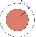
In order to put a payload into a specific orbit, a specific position and velocity vector must be achieved as illustrated in the following diagram:
This analysis will focus on achieving circular orbits in the Earth orbit. This is not the only possible orbit or trajectory (for example in GTO or interplanetary trajectories), but the results can be extrapolated to those cases if necessary. For a circular orbit, the relationship between the orbit radius and the velocity is:
Equation
- <math>v_{orbit} = \sqrt{\frac{\mu}{r_{orbit}}}</math>
Here, μ, is the Earth Gravitational Constant and has a fixed value <math display="inline">3.98574405096E14 \frac{m^3}{s^2} </math> and <math display="inline">r_{orbit}</math> is measured from the center of the Earth. If the altitude of the orbit is needed, the mean radius of the Earth equal to 6371Km must be used. As an example, a typical 500 Km circular orbit around the Earth needs a velocity of 7.61 km/s.
Geometry
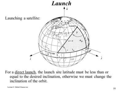
Because launch vehicles are (mostly) launched from the surface of the Earth, the geometry of the problem must be considered For a direct launch, this can be seen in the following image:
Using spherical trigonometry (https://www.orbiterwiki.org/wiki/Launch_Azimuth) it can be calculated that:
- <math> cos(i) = cos(\Phi)sin(\beta)</math>
Where i is the desired orbital inclination, β is the launch site latitude, and Φ is the launch azimuth. This restricts the orbital inclination to be always greater or equal than the launch site latitude:
- <math> i >= \Phi </math>
So for example, if the launch site is located at 30deg latitude, then it won’t be possible to direct launch the payload into an equatorial (0deg) orbit.
Another issue, that helps the launch is Earth’s rotation. Because of it, the launch site will have a tangential velocity that is dependent on the latitude as follows:
- <math> v_{earth_{due east}} = \omega_{earth} r_{earth} cos(\Phi) </math>
For example, If launching from the equator where Φ=0 the tangential velocity is maximum (about 463.7 m/s) as opposed to launching from the pole where Φ=90 and there is no tangential velocity at all. All this is only valid if launching due east which is not always the case. If you launch due East from any latitude, then β=90, so the inclination of the resultant orbit ends being the latitude of the launch. To account for this change in final inclination, the previous equation must be modified according to:
- <math> v_{earth_{due east}} = \omega_{earth} r_{earth} cos(\Phi) cos(i) </math>
So this potential gain of velocity must be taken into account when calculating the required launch strategy.
Last, if the desired orbit inclination is not achievable by a direct launch, then the launch must perform an inclination change that will require additional velocity (in a specific direction). This can be represented by:
- <math> \Delta v_{plane-change}=2V_{orbit}sin(\alpha/2) </math>
Where α is the difference in direct insertion angle to the desired angle.
Losses
During the flight and before achieving the orbital condition, there are losses of energy (or speed) that must be compensated. These losses are:
- Atmospheric drag which is the resistance of the air of the traveling vehicle
- Gravity drag which is the cost of having to hold the rocket up in a gravity field.
For a typical launch vehicle, aerodynamic losses are quite small while gravitational losses are bigger. Both depend heavily on the shape of the trajectory used and in the case of the atmospheric drag on the shape of the launch vehicle too. Usually, this will require an additional 15-20% of ΔV to compensate for these losses. 20% will be considered for the analysis.
Rocket equation
In order to achieve a change in velocity, a typical launch vehicle will utilize rocket engines that follow the Tsiolkovsky equation:
- <math>\Delta v = v_\text{e} \ln \frac{m_0}{m_f} = I_\text{sp} g_0 \ln \frac{m_0}{m_f}</math>
Where ΔV is the change of velocity of the vehicle, m0 is the initial total mass, including propellant, also known as wet mass, mf is the final total mass without propellant, also known as dry mass, ve is the exhaust velocity and is equal to Isp times g0. Here, Isp is the specific impulse in the dimension of time and is a measure of effectively the rocket use the propellant and g0 is standard gravity. In practical launch vehicles, multiple stages are stacked to create a launch vehicle that discards the unused mass as soon as possible to maximize efficiency. Also, these stages are usually tuned for each part of the flight, for example by having a high thrust to weight ratio on the first stages and a higher Isp on the last stages. For simplicity, that won’t be considered in this model.
Complete model
Considering all the factors together, to get to the desired orbit from a launch site in the earth using a rocket-propelled launch vehicle the following equation can be used:
<math> v_{orbit} + v_{drag} + v_{plane-change} - V_{earth} = I_\text{sp} g_0 \ln \frac{m_0}{m_f} </math>
Which can be rewritten as:
<math> \sqrt{\frac{\mu}{r_{orbit}}}(1 + 2 sin(\alpha/2) + v_{drag} - \omega_{earth} r_{earth} cos(\Phi)cos(i) = I_\text{sp} g_0 ln (\frac{m_0}{mf})</math>
Where:
- <math> g_0=9.81 \frac{m}{s^2} </math>
- <math> \omega_{earth} = 7.2921159 E-5 \frac{rad}{second}</math>
- <math> r_{earth} = 6371 Km</math>
where launch latitude Φ, desired orbit inclination i, plane change requirement α, target orbit radius rorbit, specific impulse Isp the masses m0 and mf are the design variables. Vdrag is left as a design variable too because it can be slightly modified with trajectory optimization and aerodynamics work.
mf represents the final mass of the system which is equal to the launch vehicle mass plus the payload mass, while m0 is the initial mass of the system which is mf plus the propellant mass mp
Morphological matrix
According to the model described above, the morphological matrix from which different launch vehicles configurations can be made is presented:
| Attribute / Options | 1 | 2 | 3 | 4 | 5 | 6 | |
|---|---|---|---|---|---|---|---|
| Stage 1 Propellant / Engine | None | LOX/LH2 | KEROLOX | Methalox | UDMH/N204 | Solid | |
| Stage 2 Propellant / Engine | None | LOX/LH2 | KEROLOX | Methalox | UDMH/N204 | Solid | |
| Stage 3 Propellant / Engine | None | LOX/LH2 | KEROLOX | Methalox | UDMH/N204 | Solid | |
| Stage 4 Propellant / Engine | None | LOX/LH2 | KEROLOX | Methalox | UDMH/N204 | Solid | |
| Launch type | Surface launch | Air launch | |||||
| Launch site | KSC | Korou | Baikonour | Air launch | |||
| Reusable | Yes | No |
As an example, a few popular and currently in operations launch vehicles are compared:
| Attribute / LV | Falcon 9 | Soyuz-FG /Fregat | Ariane 5 | Pegasus XL | LongMarch 3B |
|---|---|---|---|---|---|
| Stage 1 Propellant / Engine | KEROLOX | UDMH/N204 | LOX/LH2 + Solid | Solid | UDMH/N204 |
| Stage 1 Propellant / Engine | KEROLOX | UDMH/N204 | UDMH/N204 | Solid | UDMH/N204 |
| Stage 3 Propellant / Engine | None | UDMH/N204 | None | None | LOX/LH2 |
| Stage 4 Propellant / Engine | None | None | None | None | UDMH/N204 |
| Launch type | Surface launch | Surface launch | Surface launch | Air launch | Surface launch |
| Launch site | KSC | Baikonour | Korou | Air launch | XiChang |
| Reusable | Yes | No | No | No | No |
Sensibility analysis
In this analysis, the sensibility of the design variables for a generic launch vehicle for a particular mission is studied. The mission is the launch of a payload into a Sun-synchronous orbit with the following fixed paramters:
| Parameter | Value | Unit |
|---|---|---|
| Orbit altitude | 500 | Km |
| Inclination | 97 | degree |
| Launch latitude (KSC) | 28.57 | degree |
| Isp (LOX/LH2) | 440 | s |
| Vdrag | 1500 | m/s |
The main figure of merit under analysis will be the mass ratio r according to:
<math> J(x) = r = \frac{m_f}{m_0} = e^{-\frac{\sqrt{\frac{\mu}{r_{orbit}}}(1 + 2 sin(\alpha/2) + v_{drag} - \omega_{earth} r_{earth} cos(\Phi)cos(i)}{I_{sp}g_0}}</math>
Where the design vector is:
<math> x= [v_{drag}, \Phi, I_{sp}] </math>
So J(x0) = 11%. This means that from the total mass of the rocket, 89% must be propellant and 11% must be structure and payload (which is why it’s probably impossible to achieve yet).
Then, the possible improvements are:
- Improving the rocket efficiency (Isp)
- Improving the launch trajectory (Vdrag)
- Reducing the location of the launch site
Note that because the orbit inclination is 97 it’s actually rotating in the opposite direction of the earth so in this case, the contribution of the Earth tangential velocity must be counteracted and the sign was reversed. Also, the number 426.6 is the product of cos(97) times 463.7 m/s the tangential velocity of the Earth at the Equator.
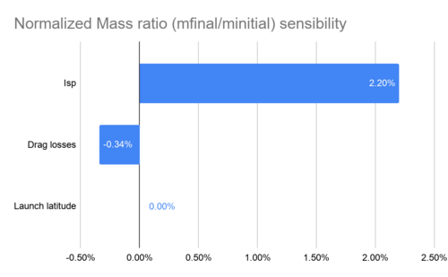
Calculating the normalized partial derivatives and considering the SSO scenario we get:
- <math> \frac{x_{i,0}}{J(X^0)}\frac{\partial r}{\partial I_{sp}}|_{x^0} = 2.20% </math>
- <math> \frac{x_{i,0}}{J(X^0)}\frac{\partial r}{\partial V_{drag}}|_{x^0} = -0.34% </math>
- <math> \frac{x_{i,0}}{J(X^0)}\frac{\partial r}{\partial \Phi}|_{x^0} = 0.003% </math>
Keys Publications and Patents
Patents
The following patents are those I found interesting from a disruptive point of view. Each of them addresses a different technology that can somehow replace the launch vehicles by performing the same final outcome which is putting payload into orbit but using completely different approaches.
Orbital mechanics of impulsive launch
Inventor: Cartland; Harry E,
Assignee: QUICKLAUNCH, INC.
United States patent 10,427,804
Date: October 1 2019
This patent is about methods to launch into orbit a spacecraft using an impulsive launch. In this case, the spacecraft is initially accelerated in a direction due east from the Earth by a high energy launch system then traveling through the atmosphere until an apogee. The patent claims different methods to further accelerate an impulse launched spacecraft in order to achieve an LEO or a trans planetary trajectory or a way to rendezvous with an orbiting spacecraft.
Space elevator
Inventor: Quine; Brendan Mark,
Assignee: THOTH TECHNOLOGY INC.
United States patent 9,085,897
Date: August 28, 2008
This patent is about an inflatable space elevator tower that can be used to deliver payloads or to install equipment to Earth Orbit. In this case, the core of the tower is constructed by cylindrical inflatable cells with gyroscopic stabilization mechanisms along with it. A pod at the top of the tower allows launching satellites using a kick stage or similar.
The US patent 6,491,258 granted to Lockheed Martin Corporation has a similar concept.
Sea landing of space launch vehicles and associated systems and methods
Inventor: Bezos; Jeffrey P.
Assignee: Blue Origin LLC
United States patent 8,678,321
Date: March 25, 2014
The first claim is a perfect description of what is being patented here: “ A method for operating a space launch vehicle, the method comprising: launching the space launch vehicle from earth in a nose-first orientation, wherein launching the space launch vehicle includes igniting one or more rocket engines on the space launch vehicle; reorienting the space launch vehicle to a tail-first orientation after launch; positioning a landing structure in a body of water; and vertically landing the space launch vehicle on the landing structure in the body of water in the tail-first orientation while providing thrust from at least one of the one or more rocket engines.”
What is very interesting is that this patent was filed by Blue Origin in 2010 and SpaceX sue them. The trial judgment granted spaceX petition and the patent was canceled. This is the resolution of the United States Patent Office. This means that now, anyone is free to attempt to land a rocket on a boat.
Papers and publications
ECONOMIC MODEL OF REUSABLE VS. EXPENDABLE LAUNCH VEHICLES Link
Author: James R. Wertz, Microcosm
Published: IAF Congress, Rio de Janeiro, Brazil Oct. 2–6, 2000
In this paper Wertz analysis the economics of expendable and reusable launch vehicles. He estimates the costs and analysis of what are the volumes at which this technology may create a significant cost reduction in the launch costs. His final conclusion was: “A factor of 5 to 10 near term reduction in launch cost appears feasible. That should increase the size of the market, which can then lead to lower costs in the future.”
Parametric Model of an Aerospike Rocket Engine Link
Author: J. J. Korte NASA Langley Research Center
Published: 38th Aerospace Sciences Meeting & Exhibit 10-13 January 2000 / Reno, NV
In this paper, the author develops a mathematical and executable model of an aerospike engine that can be used in conjunction with other models to simulate launch trajectories utilizing this type of engine. This engine has been under study for decades and the special interests rely on the theoretical high efficiency across different altitudes that can be achieved. No aerospike engine has ever flown to space yet.
