Difference between revisions of "WorldWide eVTOL"
| Line 196: | Line 196: | ||
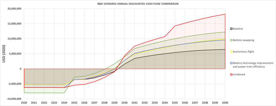
# Baseline: | # Baseline: | ||
-- Incur a 10 million R&T cost evenly distributed over the first 5 years of timeframe | -- Incur a 10 million R&T cost evenly distributed over the first 5 years of timeframe | ||
-- No additional R&D costs. | -- No additional R&D costs. | ||
# Battery swapping: | # Battery swapping: | ||
-- Incur a 10 million R&T cost evenly distributed over the first 5 years of timeframe | -- Incur a 10 million R&T cost evenly distributed over the first 5 years of timeframe | ||
-- Incur an 8 million developmental and integration cost of battery swapping technology evenly distributed over the first 5 years of timeframe. This R&D research was assumed to be done at the beginning of the venture since produce design would be designed around battery swapping operations. | -- Incur an 8 million developmental and integration cost of battery swapping technology evenly distributed over the first 5 years of timeframe. This R&D research was assumed to be done at the beginning of the venture since produce design would be designed around battery swapping operations. | ||
# Autonomous flight: | # Autonomous flight: | ||
-- Incur a 10 million R&T cost evenly distributed over the first 5 years of timeframe | -- Incur a 10 million R&T cost evenly distributed over the first 5 years of timeframe | ||
-- Incur a 10 million R&D cost evenly distributed over the first 10 years of timeframe. A 10 year to-deployment timeframe was assumed to reflect the potential technological, regulatory and certification hurdles associated with autonomous flight. | -- Incur a 10 million R&D cost evenly distributed over the first 10 years of timeframe. A 10 year to-deployment timeframe was assumed to reflect the potential technological, regulatory and certification hurdles associated with autonomous flight. | ||
# Battery technology improvement and power train efficiency: | # Battery technology improvement and power train efficiency: | ||
-- Incur a 10 million R&T cost evenly distributed over the first 5 years of timeframe | -- Incur a 10 million R&T cost evenly distributed over the first 5 years of timeframe | ||
-- Incur a 8 million R&D cost associated with external battery technology improvement investment evenly distributed over the first 5 years of timeframe | -- Incur a 8 million R&D cost associated with external battery technology improvement investment evenly distributed over the first 5 years of timeframe | ||
-- Incur a 6 million R&D cost associated with internal power train efficiency investment evenly distributed over the first 5 years of timeframe | -- Incur a 6 million R&D cost associated with internal power train efficiency investment evenly distributed over the first 5 years of timeframe | ||
Revision as of 22:59, 17 November 2020
Technology Roadmap Sections and Deliverables
- 2EVL Eletric Vertical take off and Landing
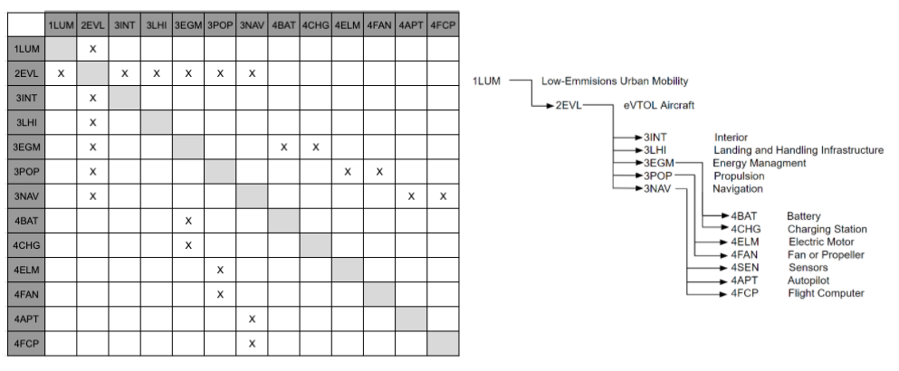
This indicates that we are dealing with a “level 2” roadmap at the product level (see Fig. 8-5), where “level 1” is a market level roadmap 1LUM (Low emissions Urban air Mobility)and “level 3” or “level 4” would indicate the specific technologies like vectored thrust, autonomous flight, electric propulsion etc.
Roadmap Overview
Enter description of the technology here:
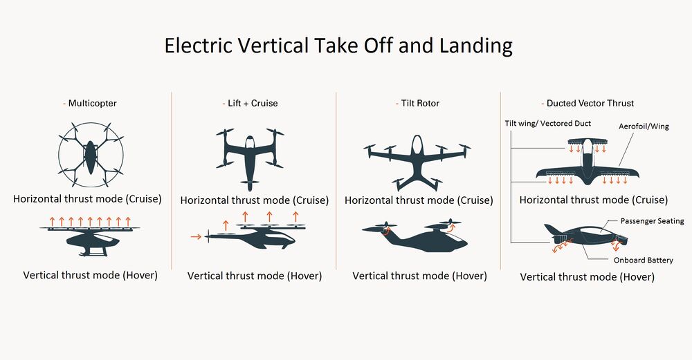
eVTOLS (electric Vehicle Take Off and Landing) are airborne vehicles that use electric vectored thrust to take off vertically and transition from vertical thrust to horizontal thrust, thus making it flexible and efficient for Urban air commute. <ref>https://en.wikipedia.org/wiki/EVTOL</ref> The vectored thrust eVTOLs have a wing for an efficient cruise and use the same propulsion system for both hover and cruise. They are conceptually simple but difficult and risky to control. The tail-sitters rotate the entire aircraft. They are conceptually simple but difficult and risky to control. The Harrier configuration is called vectored thrust because it can orientate mechanically the direction of the thrust. The tilt-wings rotate the entire wing, the engines and the propellers as a single piece. Rotating the wing in hover avoids the impinging of the propeller slipstream on it, a problem that reduces the thrust in the hover of tiltrotors. The lift produced by the wing is augmented, at high angles of attack, by the blowing effect of the propellers. Autonomous eVTOLs are more versatile and can be efficiently used to transport passengers and cargo without any human intervention yet are often available as optionally pilotable. <ref>Electric VTOL Configurations Comparison by Alessandro Bacchini</ref>
<ref>Lilliumjet, architecture design principles</ref>
Design Structure Matrix (DSM) Allocation
The 2-EVL tree that we can extract from the DSM above shows us that the eVTOL (2EVL) is a solution to larger more fuel efficient methods of urban mobility (1LUM), and requires the following major subsystems: 3INT Interior, 3LHI Landing and Handling Infrastructure, 3EGM Energy Management, 3POP Propulsion, and 3NAV Navigation. These require the following level four component technologies: 4BAT Battery, 4CHG Charging Station, 4ELM Electric Motor, 4FAN Fan or Propeller, 4SEN Sensors, 4APT Auto-pilot and 4FCP Flight Computer.
Roadmap Model using OPM
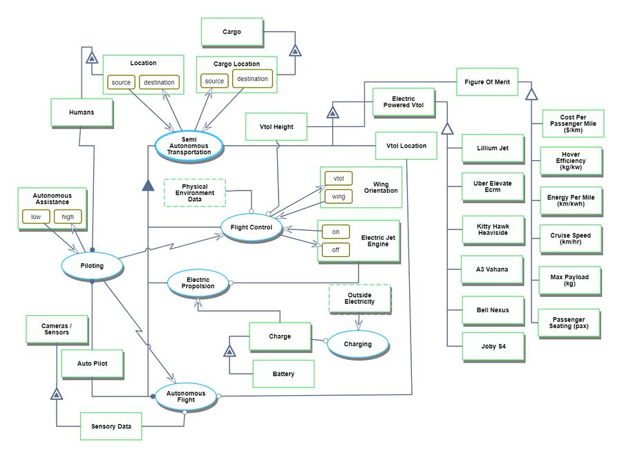
We provide an Object-Process-Diagram (OPD) of the 2EVL roadmap in the figure below. This diagram captures the main object of the roadmap (eVTOL), its various instances including main competitors, its decomposition into subsystems (wing, flight-control, autonomous control, electric propulsion), its characterization by Figures of Merit (FOMs) as well as the main processes (hovering, wing tilt).
An Object-Process-Language (OPL) description of the roadmap scope is auto-generated and given below. It reflects the same content as the previous figure, but in a formal natural language.
Figures of Merit
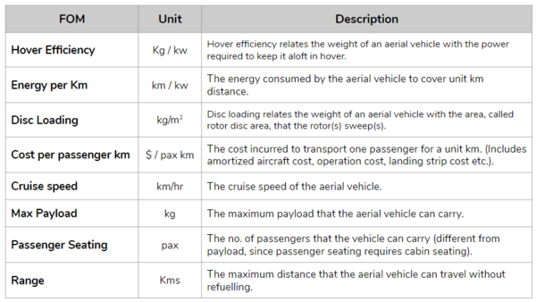
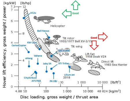
The table below show a list of FOMs by which electric VTOL can be assessed. The first two and the last two are used to assess the aircraft itself. They are very similar to the FOMs that are used to compare traditional aircraft which are propelled by fossil fuels, the big difference being that 2EVL is essentially emissions free during flight operations. The other rows represent subordinated FOMs which impact the performance and cost of eVTOL but are provided as outputs (primary FOMs) from lower level roadmaps at level 3 or level 4, see the DSM above.
 <ref>Back to the Future: A rough comparison of 70s VTOL concepts to current eVTOL designs - Mykhaylo Filipenko</ref>
Alignment with Company Strategic Drivers
Strategic drivers for the company:
| Number | Strategic Drivers | Alignment targets |
|---|---|---|
| 1 | To develop hover and cruise configurations to lower the net cost to the passenger for intercity flights in a limited service radius. The design of the eVTOL itself should enable reduced CAPEX costs and OPEX costs for a flight over a limited radius. The current air transportation modes either result in high CAPEX (Airports) or high OPEX (Helicopters, multirotors) that drive the cost up. | This roadmap will target the technology selection that would address the need for high hover efficiency for take-off and landing and high cruise efficiency for covering higher distances. The state of the art technology of tilt rotors and tilt wing aircrafts seem to enable the use of a common propulsion system for hover and cruise, leveraging the best of both aircrafts and rotorcraft(conventional). This roadmap evaluates various configurations of eVTOLs and this driver is aligned with this roadmap. |
| 2 | To target higher PAX capacities while keeping a balance with a decent range to enable cost effective transportation to surrounding cities, making the hub & spoke transportation model a reality. Efficient propulsion systems would increase the efficiency of the eVTOL creating room for more passengers or higher ranges. | The development of the Li-ion batteries with higher energy density is crucial to increased payload capacity of eVTOLs. THe Li-ion energy density has tripled since 2010 to 300Wh/Kg. To achieve a long range flight, a target of 500Wh/Kg is expected by 2025. The weight of the eVTOL itself plays a major role in this. Use of lighter materials like aluminum and carbon fiber are expected for the construction of the eVTOL. This driver is in alignment of the 2EVL roadmap |
| 3 | To develop low noise hover systems with lower disc loading in order to allow for the eVTOL to take off from various landing ports in urban areas. THe reduced noise and disc loading will enable the construction of compact landing pads in buildings or courtyard without disrupting normal urban life. | The discloading of the aircraft severely impacts the noise level generated by the hover. The harrier jet generates 125 dB of noise when hovering at 100ft, whereas helicopters generate 108 dB at ground level. Reduction of these to 78 dB is required in order to achieve the desirable noise level. This driver is currently not aligned with the eVTOLs. |
.
Positioning of Company vs. Competition
The table below contains publicly available high level specification data for the key e-VTOL aircraft designs currently in the R&D, prototyping or production technology developmental phases.
It is worth noting here that this table contains data for a variety of e-VTOL flight configurations. Each configuration has its pros and cons and the industry has not yet converged to an optimal configuration yet. Multicopter aircraft are typically designed to serve short-haul intra-city demand whilst tilt-wing, tilt-rotor and lift+push configurations achieve efficiency in cruise flight and therefore typically serve inter-city demand. Not all of these aircraft are in at the prototyping or production stages; some still remain conceptual. Performance specifications from such designs are subject to change in the future.
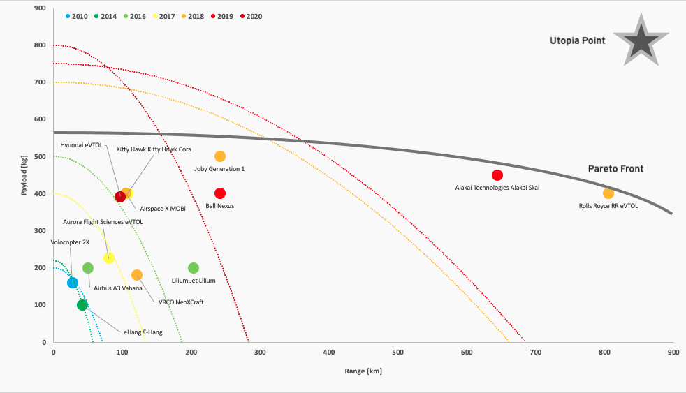
This figure highlights the trade-off that exists between flight range [km] and max payload capacity [kg] and presence of a pareto front that pushes to the top right of the chart. With e-VTOLs first making headlines in 2010 with the e-Hang announcement, players have adopted different methods to move closer to the utopia point. This chart is somewhat skewed by Alakai Technologies' Alakai Skai and Rolls Royce's e-VTOL aircraft. Both are still conceptual designs with to-market strategies in the late 2020's and early 2030's. Both promise exceptional range and PAX capacity with substantially larger aircraft airframes than what is currently seen on the market today. Alakai Skai is also unique in that it is the only e-VTOL with a hydrogen-powered fuel plant, a technology that underpins their bullish performance metrics.
Both Volocopter and e-Hang are focused on the intra-city short-haul transportation market whilst players such as Lilium and Joby are more focused on inter-city operations. In the early 2010's, we see a focus on range over PAX capacity in an effort to dissolve doubts around operational feasibility. With that said, more recent e-VTOL designs sport large PAX capacities for similar or more range, signaling a shift from technological development and R&D focused on core performance parameters such as range to more operational considerations such as PAX capacity. This industry has not yet seen any notable consolidation efforts in part because it remains a nascent industry without any realized demand. With that said, as certification processes begin to hinder to-market strategies, consolidation may occur between players with compatible technology or operational synergies. Furthermore, whilst the market is crowded with feasible e-VTOL designs, competition is not necessarily fully realized in as the industry grows as players will likely benefit from co-existence. We can expect to see synergies between direct competitors with regards to certification processes, driving customer and public acceptance and any infrastructure-related investment that is required at the industry level.
Technical Model
Morphological Matrix
An eVTOL system is complex, with many subsystems that all must be designed and optimized to achieve desired overall performance. The following morphological matrix contains some of the governing physical parameters that impact the aerodynamic performance of the aircraft.
| Decision Variable | E-Hang | Cora | Lilium |
|---|---|---|---|
| Wing Area [m^2] | N/A | 10 | 3.6 |
| Wingspan [m] | N/A | 11 | 6 |
| Disk Actuator Area [m^2] | 8.04 | 13.6 | 0.64 |
| Number of Lift Devices | 4 | 12 | 36 |
| Total Mass (kg) | 260 | 1224 | 490 |
FOM Sensitivity Analysis
Fundamental equations for eVTOL range and cost per trip were generated which include some of the parameters in the morphological matrix shown above.
The model for range is based on the Breguet Range Equation. This equation is adopted for electric aircraft to include the energy density of the battery-electric system over fuel properties as in the traditional Breguet Range Equation to take the form
<math> R = E^{*}*\eta_{total}*\frac{1}{g}*\frac{L}{D}*\frac{m_{battery}}{m_{total}} </math>
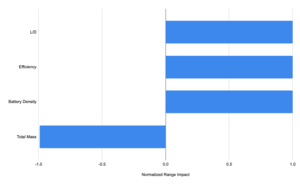
where <math>E^*</math> is the specific energy of the battery system, <math>\eta_{total}</math> is the overall efficiency, L is lift, D is Drag and m is mass. This simple equation contains a lot of information about the impacts of the vehicle and propulsive system parameters on the system. A sensitivity analysis was performed on the L/D, total mass, energy density, and total efficiency, producing the tornado chart shown.
The plot shows that there is a positive 1:1 relationship between increases in overall system efficiency, L/D, and battery energy density to aircraft range. Conversely, there is an inverse relationship between the overall mass of the system and the range.
The other technical model created is for cost per flight of the eVTOL aircraft. The high level governing equation includes a cost per hour of crew wages, an amortized unit cost, and the energy cost of the flight as shown below.
<math> Cost_{flight} = \frac{Cost_{vehicle}}{n_{lifetime flights}} + Cost_{crew/hr}*\left(t_{takeoff}+t_{landing}+\frac{V_{cruise}}{R_{trip}}\right)+Cost_{energy}*E_{flight} </math>
To develop a cost model that can be compared across multiple platforms, a baseline mission of fixed-time takeoff and landing periods, and a set-distance cruise was considered. These times, <math> t_{takeoff} </math> and <math> t_{landing} </math> are seen in the equation above. To determine the amount of energy needed for the flight, the mission segments must be broken down into their components. First, the power required to hover,
<math> P_{hover} = \sqrt{\frac{\frac{T}{T_{i}}^{3}}{2\rho A}} </math>
is considered where T is thrust, <math> T_i </math> is a scaling factor depending on propulsor type, <math> \rho </math> is air density, and A is the disk actuator area. This power quantity can be combined with the energy needed for a fixed range by rearranging the Breguet Range Equation shown above, which gives
<math> E_{flight} = P_{hover}*t_{takeoff}+P_{hover}*t_{landing}+E_{cruise} </math>
as the overall equation for energy consumed on a flight. Substituting back into the original cost model, yields
<math> Cost_{flight} = \frac{Cost_{vehicle}}{n_{lifetime flights}} + Cost_{crew/hr}*\left(t_{takeoff}+t_{landing}+\frac{V_{cruise}}{R_{trip}}\right)+Cost_{energy}*\sqrt{\frac{\frac{T}{T_{i}}^{3}}{2\rho A}}*\left[t_{takeoff}+t_{landing}+\frac{R}{\eta_{total}*\frac{1}{g}*\frac{L}{D}*\frac{m_{battery}}{m_{total}}}\right] </math>
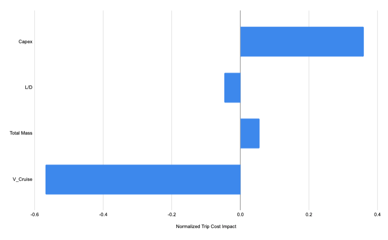
as the final equation for cost per flight, including all pertinent vehicle parameters. This final equation, with the underlying parameters embedded in these values, was analyzed for normalized sensitivity to changes in the Unit Cost, or Capex, Lift-to-drag ratio of the aircraft, total aircraft mass, and cruise velocity. These sensitivities are plotted and shown in the corresponding tornado chart.
Due to the relatively low cost of electricity compared to amortized capital expenses and crew wages, for this mission set, the impacts of the parameters that feed into <math>E_{flight}</math> are negligible. This figure shows the positive relationship between up-front capital costs of the aircraft and the cost per trip, along with the aircraft mass. Conversely, the eVTOL's cruise velocity and L/D are inversely proportional to the cost per trip. Thus, according to the chart above, the most impactful way to lower trip cost for the analyzed mission is to increase the cruise velocity.
Key Patents and Publications
Patents
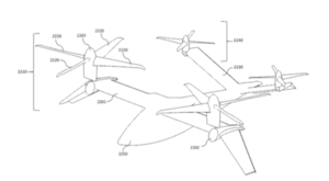
Karem Aircraft: EVTOL Aircraft Using Large, Variable Speed Tilt Rotors
This patent, US 10,351,235, covers a specific eVTOL architecture consisting of four electrically driven rotors, and a horizontal wing-tail configuration. The aircraft is described to have a payload of 500-1300 lbs, and the range is not specified. This aircraft concept achieves vertical flight through articulating “tilt-rotors” on each of the four rotors in the concept. During vertical flight, they are all operating in the horizontal plane, providing vertical thrust for vertical take-off and landing. The aircraft has a long major wing, and a smaller tailplane behind it, each with two of the motor-propeller assemblies. In translational flight, the aircraft relies on the wing for lift, and the motors are responsible only for producing thrust. The rear rotors are on the ends of the horizontal tailplane, while the main rotors are near the end, with a wing extension protruding beyond.
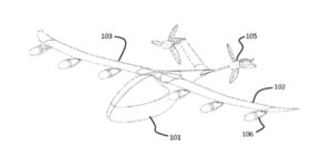
Joby Aviation: Aerodynamically Efficient Lightweight Vertical Takeoff and Landing Aircraft with Pivoting Rotors and Stowing Rotor Blades
US patent 20160031555A1 by Joby Aviation covers three different concepts of tiltrotor aircraft, each of which rely on pivoted electric rotor assemblies for vertical thrust, and on wings for lift in horizontal flight. One of the key features of this aircraft concept is the forward-swept wing with either three or four electric rotors on each side. This is due to mass balancing, and wing spar placement considerations. Additionally, the patent covers Joby’s plan to have rotors that can articulate and nest within the nacelle during forward flight. Because the rotors have to provide all of the lift in vertical flight, the rotor system is sized for this condition, not for the thrust needed in horizontal flight. By stowing the motors when they aren't needed, significant aerodynamic gains can be achieved. Lastly the rotor assemblies are able to pivot with respect to the engine nacelles due to a design shown in detail in the patent. The actuator-driven pivoting of the motor/propeller assembly can potentially simplify the architecture, as the surrounding wing structure does not have to accommodate a pivoting nacelle.
Opener: Electrically Powered Aerial Vehicles and Flight Control Methods
US Patent 9,346,542 by Opener describes the core technology and configuration for their Blackfly eVTOL aircraft technology. The overall layout of this aircraft is two straight wings that are located in the front and back of the aircraft and are vertically staggered from each other. Each wing has four motor-propeller rotor assemblies which are powered from a central battery. Currently, the Blackfly technology is only a single-seat aircraft and the patent describes it as such. Each wing assembly with embedded rotors rotates about its own axis to provide thrust for both vertical and horizontal flight. Additionally, this design has no control surfaces. The control and navigation of this concept is controlled by modulating the thrust provided to each independent rotor assembly. Through this differential thrust, the aircraft is able to pitch, roll and yaw, along with possessing control capabilities while hovering. The patent also covers a detailed energy and information flow diagram that shows how both power and control information are provided to each motor assembly. This patent does not cover the mechanics of the wing assemblies, their rotation, or any mention of the intended uses of the aircraft. Overall this patent concisely describes the single-person aircraft from a high level, but does not mention any specifics about some of the mechanical challenges that this design possesses.
Publications
Electric VTOL Configurations Comparison
Alessandro Bacchini and Enrico Cestino, 2019
This paper by Alessandro Bacchini and Enrico Cestino consists of a thorough comparison of three major types of eVTOL aircraft system architectures and evaluates their performance in three unique sample missions. The three types of aircraft are demonstrated and compared by investigating the performance of three commercial offerings, the E-Hang, Kitty Hawk Cora, and Lilium Jet. The E-Hang represents a wingless configuration where vertical and horizontal thrust, and lift in horizontal flight are all provided by rotor assemblies. The Cora is a lift-cruise aircraft where lift and cruise propulsion are provided by unique motor assemblies. This aircraft has wings to provide lift in horizontal flight, twelve horizontal rotors which provide vertical thrust, and a single motor which powers a pusher propeller for horizontal thrust. The Lilium Jet represents the last architecture, which has fixed horizontal wings and a propulsion system that pivots between a horizontal and vertical orientation to provide vertical and horizontal thrust.
This paper provides a review of each aircrafts performance by drawing on aerodynamic first principles. The sample mission sets have a hover, acceleration, cruise, deceleration, and landing hover portion, which vary in length between the three. Each aircraft configuration is analyzed for cruise and hover performance, and the overall power and energy required for each leg of the mission is compared. For hover, the E-Hang outperforms the other two configurations, while the Lilium Jet is the best during cruise. The Cora represents a compromise between the two systems. Overall this paper represents a thorough approach to compare various eVTOL concepts against one another. One criticism is that it is missing the tilt-rotor propeller architecture, which constitutes a large segment of the industry.
A Review of Configuration Design for Distributed Propulsion Transitioning VTOL Aircraft
D. Felix Finger, Carsten Braun, and Cees Bil, 2016
This paper, by D. Felix Finger, Carsten Braun, and Cees Bil, provides an overview of the tradeoffs between many different solutions to the eVTOL aircraft system. In total, fifteen unique configurations of transitioning flight aircraft are considered. These systems are those where wings are relied on as a primary means of producing lift during horizontal flight. Concepts discussed ranged from jet-lift fan configurations like the F-35B, to tilt-duct arrangements as seen on the Bell 65. Additionally, there is a discussion of rotorcraft technologies including the helicopter and various multicopter configurations.
Financial Model
This financial model is performed from the perspective of a dual manufacturer and operator of an inter-city e-VTOL passenger transport service. The breakdown of the profit and loss statement is as follows:
- Annual profits are derived from revenues and costs:
- Revenues
- Revenues are in turn solely derived by ticket sales for the passenger transport service, and notably not from any auxiliary sales of the e-VTOL aircraft to other operators or in alternative industries or use cases.
- Revenue is driven solely by the number of flights flown in a year, the average PAX load per flight and the average ticket price per PAX per flight.
- Flights flown per year is estimated via a bottom-up approach based off the number of vehicles in the operating fleet each year and their daily utilization rates.
- An average PAX load of 1 is assumed throughout. This is to reflect near-term regulatory and technology constraints on PAX load.
- The average ticket price is benchmarked off of competing alternative transport modes with convenience of e-VTOL transport included as a price multiple.<ref>https://ntrs.nasa.gov/search.jsp?R=20190001472</ref>
- Costs
- Variable costs: sub-divided into electricity for e-VTOL charging, labour, maintenance and landing fees
- Fixed costs: sub-divided into overhead (in turn divided into rent and administrative) and insurance
- Capital costs: sub-divided into vehicle manufacturing, depreciation, battery acquisition, charging infrastructure and spares.
- Revenues
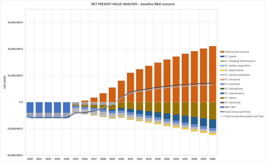
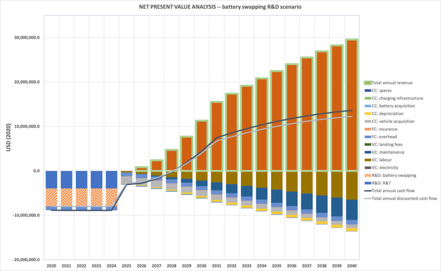
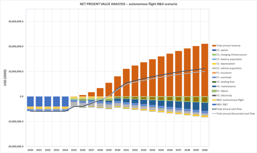
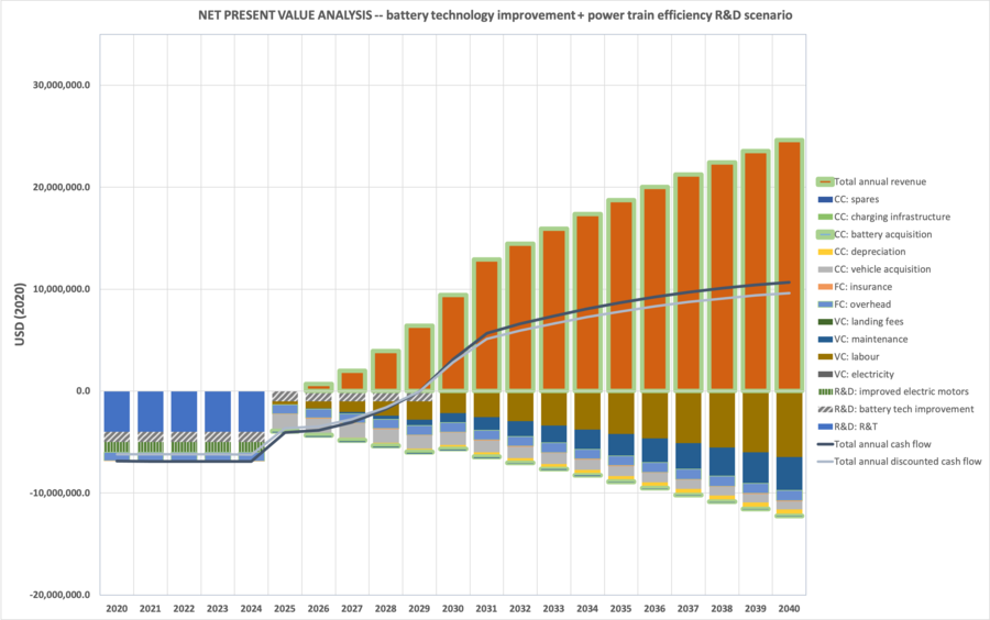
We decided to utilize this financial model to perform sensitivity analysis on the various potential R&D projects within the purview of an e-VTOL manufacturer and operator. The R&D projects we modeled were: 1) the baseline R&T product development; 2) battery swapping technology integration; 3) autonomous flight systems integration; 4) general battery technology improvement and power train efficiency investment. Now discussing the financial implications of each in turn:
- Baseline:
-- Incur a 10 million R&T cost evenly distributed over the first 5 years of timeframe
-- No additional R&D costs.
- Battery swapping:
-- Incur a 10 million R&T cost evenly distributed over the first 5 years of timeframe
-- Incur an 8 million developmental and integration cost of battery swapping technology evenly distributed over the first 5 years of timeframe. This R&D research was assumed to be done at the beginning of the venture since produce design would be designed around battery swapping operations.
- Autonomous flight:
-- Incur a 10 million R&T cost evenly distributed over the first 5 years of timeframe
-- Incur a 10 million R&D cost evenly distributed over the first 10 years of timeframe. A 10 year to-deployment timeframe was assumed to reflect the potential technological, regulatory and certification hurdles associated with autonomous flight.
- Battery technology improvement and power train efficiency:
-- Incur a 10 million R&T cost evenly distributed over the first 5 years of timeframe
-- Incur a 8 million R&D cost associated with external battery technology improvement investment evenly distributed over the first 5 years of timeframe
-- Incur a 6 million R&D cost associated with internal power train efficiency investment evenly distributed over the first 5 years of timeframe
