Difference between revisions of "Space-based Solar Power"
| (28 intermediate revisions by the same user not shown) | |||
| Line 92: | Line 92: | ||
==Positioning of Company vs. Competition: FOM charts== | ==Positioning of Company vs. Competition: FOM charts== | ||
[[File: LCOE_vs_Power_Output_Capacity_Comparison.png | | [[File: LCOE_vs_Power_Output_Capacity_Comparison.png |600px|center]] | ||
This chart compares the Levelized Cost of Electricity (LCOE) and the Power Output Capacity for various power generation technologies. The X-axis represents the LCOE values in USD per megawatt-hour (MWh), sourced from the U.S. Energy Information Administration (EIA) report. LCOE is a key indicator of the cost-effectiveness of different power generation methods, considering the total lifetime costs divided by the total electricity output over the plant’s operational life. The Y-axis represents the Power Output Capacity in megawatts (MW), which indicates the maximum electrical output that each type of power plant can generate. Since the capacity depends on the scale and specific design of each facility, the chart displays a range of typical values as a reference for each technology. These ranges reflect the variety of installations, from smaller local plants to large-scale facilities. | This chart compares the Levelized Cost of Electricity (LCOE) and the Power Output Capacity for various power generation technologies. The X-axis represents the LCOE values in USD per megawatt-hour (MWh), sourced from the U.S. Energy Information Administration (EIA) report[Ref4]. LCOE is a key indicator of the cost-effectiveness of different power generation methods, considering the total lifetime costs divided by the total electricity output over the plant’s operational life. The Y-axis represents the Power Output Capacity in megawatts (MW), which indicates the maximum electrical output that each type of power plant can generate[Ref4-9]. Since the capacity depends on the scale and specific design of each facility, the chart displays a range of typical values as a reference for each technology. These ranges reflect the variety of installations, from smaller local plants to large-scale facilities. | ||
[[File: Roland_Berger_INS_869_Study_ESA_SBSP_GT_02_image_caption_w1280.jpg | | [[File: Roland_Berger_INS_869_Study_ESA_SBSP_GT_02_image_caption_w1280.jpg |700px|center]] | ||
The Roland Berger study for the European Space Agency (ESA) highlights the promising potential of SSP in the future energy market. According to the report, by 2050, the Levelized Cost of Energy (LCOE) for the first operational SBSP system could reach around 69 EUR/MWh ($73/MWh). Additionally, with the learning curve effect, the LCOE might decrease to approximately 49 EUR/MWh ($52/MWh) after deploying the first 10 SSP stations. | The Roland Berger study for the European Space Agency (ESA) highlights the promising potential of SSP in the future energy market[Ref10]. According to the report, by 2050, the Levelized Cost of Energy (LCOE) for the first operational SBSP system could reach around 69 EUR/MWh ($73/MWh). Additionally, with the learning curve effect, the LCOE might decrease to approximately 49 EUR/MWh ($52/MWh) after deploying the first 10 SSP stations. | ||
This suggests that SSP could achieve a competitive LCOE compared to other power generation technologies.The economic viability of SSP will depend on factors such as climate policy implementation and future energy supply conditions. The study outlines scenarios with electricity prices ranging from 25 to 300 EUR/MWh (~$27 to ~$319/MWh), indicating that SSP could be economically competitive within this range. | This suggests that SSP could achieve a competitive LCOE compared to other power generation technologies.The economic viability of SSP will depend on factors such as climate policy implementation and future energy supply conditions. The study outlines scenarios with electricity prices ranging from 25 to 300 EUR/MWh (~$27 to ~$319/MWh), indicating that SSP could be economically competitive within this range. | ||
| Line 104: | Line 104: | ||
| | ||
=Technical Model: Morphological Matrix and Tradespace= | ==Technical Model: Morphological Matrix and Tradespace== | ||
The morphological matrix displays the primary technology options available at the initial level of decomposition, as shown in the figure below. Our chosen selections are highlighted in green. | |||
[[File: SSP_MorMatrix.jpg |900px|center]] | |||
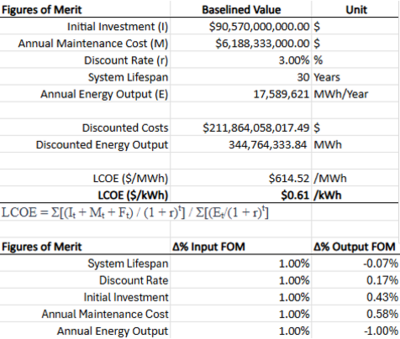
The | This tornado chart illustrates the sensitivity analysis of the Levelized Cost of Electricity (LCOE). The horizontal axis shows the percentage change in LCOE for a 1% variation in each input Figure of Merit (FOM). The chart reveals that Annual Energy Output has the most significant impact on LCOE, followed by Annual Maintenance Cost and Initial Investment. In contrast, the effects of Discount Rate and System Lifespan are relatively smaller. This analysis helps identify the key factors that can effectively reduce LCOE. | ||
[[File: SSP_LCOE.png |500px]] | [[File: SSP_LCOE.png |500px]] | ||
[[File: SSP_LCOE_FOM.png |400px]] | [[File: SSP_LCOE_FOM.png |400px]] | ||
| Line 123: | Line 122: | ||
=Keys Publication and patents= | ==Keys Publication and patents== | ||
Key | ===Key Publication=== | ||
1. Space-Based Solar Power, Rodgers, E., et al., NASA Office of Technology, Policy, & Strategy | ===== 1. Space-Based Solar Power, Rodgers, E., et al., NASA Office of Technology, Policy, & Strategy, 2024 ===== | ||
: The study focuses on the feasibility of a 2-gigawatt SSP system and explores the questions of the mission design (one large system or multiple smaller ones), lifecycle calculations, and performed sensitivity analyses on various factors. The results are summarized in Figure 1. Their conclusions were that the most competitive options used lower launch costs, electric propulsion from LEO to GEO, long service lifetimes, cheaper servicing vehicles, and efficient large-scale production. Although currently estimated to be 12-80 times more costly than terrestrial alternatives, further advancements may make this technology feasible. | |||
::Power beaming was not considered as part of the sensitivity analysis, and is a key technical challenge for SSP. Although demonstrated in June 2023 at Caltech, significant improvements still need to be made for a system of this scale3. | |||
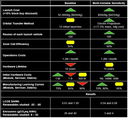
: | [[File: Publication1.png |500px|center|thumb| Figure 1: Results of a sensitivity analysis of factors critical to a successful SSP system. Green triangles show capabilities already achieved, yellow achievable today, and red triangles are below today's capability.[Ref12]]] | ||
===== 2. A new concept of space solar power satellite, Li X. et al. 2017 ===== | |||
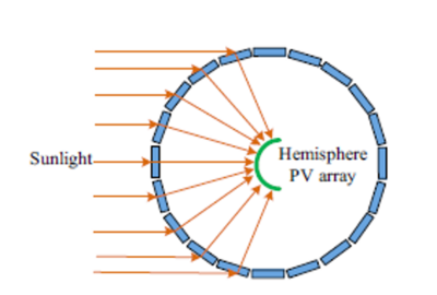
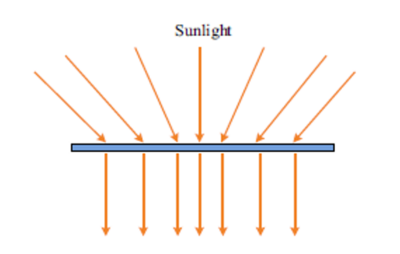
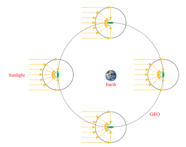
: This publication describes a concept for SSP that heavily utilizes ε-near-zero metamaterial to focus sunlight normal to a photovoltaic array as depicted in Figures 1 and 2. The purpose of this is to improve efficiency and reduce the mass of the overall system, which is a major concern due to launch and manufacturing costs when the example system would need a spherical condenser with a diameter of 1.5 km. To reduce the number of systems needed, a geosynchronous orbit is recommended. After focusing the sunlight on the PV array, the generated DC power would be transmitted through a 1km antenna at 5.8 GHz to a 4km diameter rectenna on the ground. An overall concept is depicted in Figure 3. | |||
:: | <gallery widths="400" heights="300"> | ||
File: Publication2.png |500px]|thumb|Figure 2 [Ref14] | |||
File: Publication3.png |500px]|thumb|Figure 3 [Ref14] | |||
File: Publication4.png |500px]|thumb|Figure 4 [Ref14] | |||
</gallery> | |||
Patents | ===Patents=== | ||
A. CPC Classification: H02S 40/22, H02S 40/20, Y02E 10/52 | =====A. CPC Classification: H02S 40/22, H02S 40/20, Y02E 10/52 ===== | ||
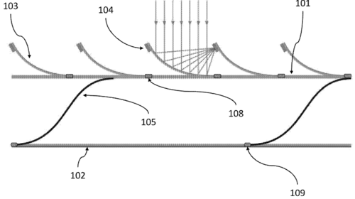
: The patent describes this technology as "a structural substrate body having an array of solar concentrators configured to receive and re-direct solar radiation onto a plurality of photovoltaic (PV) cells". As depicted in Figure 5, this allows a user to reduce the amount of area covered with PV arrays while still capturing the energy from a larger area. Placing the PV cell as depicted in the figure also allows greater efficiencies by not requiring a separate structural support – the reflectors (#103) and PV cells (#104) utilize the same ones. | : The patent describes this technology as "a structural substrate body having an array of solar concentrators configured to receive and re-direct solar radiation onto a plurality of photovoltaic (PV) cells". As depicted in Figure 5, this allows a user to reduce the amount of area covered with PV arrays while still capturing the energy from a larger area. Placing the PV cell as depicted in the figure also allows greater efficiencies by not requiring a separate structural support – the reflectors (#103) and PV cells (#104) utilize the same ones. | ||
[[File: Patents1.png |500px|center]] | [[File: Patents1.png |500px|center|thumb| Figure 5 [Ref15]]] | ||
B. CPC Classification: H04B 7/18513, B64G 1/428; H02S 40/30 | ===== B. CPC Classification: H04B 7/18513, B64G 1/428; H02S 40/30 ===== | ||
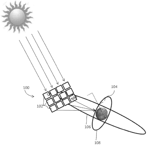
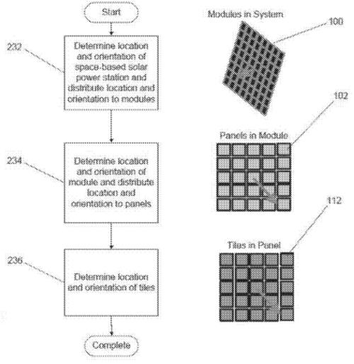
: As mentioned earlier in the publication study, sunlight needs to be focused normal to the PV array to achieve the highest efficiency. This patent covers several methods of achieving this in a SSP system using sun sensors in configuration to coordinate turning the tiles for the highest intensity of illumination. A wide number of methods are included such as placing sensors directly on the tiles, orienting them around the area on the spacecraft, receiving signals from other systems (such as GPS), and even smaller sensor spacecraft orbiting the main spacecraft that transforms and beams the energy. A general concept depiction is shown in Figure 6 and the generic process is shown in Figure 7. | : As mentioned earlier in the publication study, sunlight needs to be focused normal to the PV array to achieve the highest efficiency. This patent covers several methods of achieving this in a SSP system using sun sensors in configuration to coordinate turning the tiles for the highest intensity of illumination. A wide number of methods are included such as placing sensors directly on the tiles, orienting them around the area on the spacecraft, receiving signals from other systems (such as GPS), and even smaller sensor spacecraft orbiting the main spacecraft that transforms and beams the energy. A general concept depiction is shown in Figure 6 and the generic process is shown in Figure 7. | ||
[[File: Patentssp2.png |500px]] | [[File: Patentssp2.png |500px|center|thumb| Figure 6 [Ref16]]] | ||
[[File: Patentsssp3.png |500px]] | [[File: Patentsssp3.png |500px|center|thumb| Figure 7 [Ref16] ]] | ||
| | ||
| Line 185: | Line 190: | ||
[10] Hader, M., & Hoyer, M. (2022). Space-based solar power: Helping decarbonize Europe and make it more energy resilient thanks to electricity generated in space. Roland Berger. https://www.rolandberger.com/en/Insights/Publications/Space-based-Solar-Power.html | [10] Hader, M., & Hoyer, M. (2022). Space-based solar power: Helping decarbonize Europe and make it more energy resilient thanks to electricity generated in space. Roland Berger. https://www.rolandberger.com/en/Insights/Publications/Space-based-Solar-Power.html | ||
[ | [11] NASA. (2013). Flight Avionics Hardware Roadmap (NASA/TM–2013-217986). https://ntrs.nasa.gov/api/citations/20130013356/downloads/20130013356.pdf | ||
[ | [12] NASA. (2024, January). Space-Based Solar Power: A NASA Technology Assessment. NASA Office of Technology, Policy, and Strategy. https://www.nasa.gov/wp-content/uploads/2024/01/otps-sbsp-report-final-tagged-approved-1-8-24-tagged-v2.pdf | ||
[ | [13] Caltech. (2023, June 1). In a First, Caltech's Space Solar Power Demonstrator Wirelessly Transmits Power in Space. California Institute of Technology. https://www.caltech.edu/about/news/in-a-first-caltechs-space-solar-power-demonstrator-wirelessly-transmits-power-in-space | ||
[ | [14] Li, X., Duan, B., Song, L., Yang, Y., Zhang, Y., & Wang, D. (2017). A new concept of space solar power satellite. Acta Astronautica, 136, 255-264. https://www.sciencedirect.com/science/article/pii/S0094576516311092 | ||
[ | [15] Mankins, J. C. (2021). U.S. Patent No. 10,992,253. Washington, DC: U.S. Patent and Trademark Office. | ||
[ | [16] Mankins, J. C. (2019). U.S. Patent No. 10,454,565. Washington, DC: U.S. Patent and Trademark Office. | ||
Latest revision as of 04:34, 5 November 2024
Technology Roadmap Sections and Deliverables
- 2SSP - Space-based Solar Power
We’ve chosen the acronym 2SSP to represent our technology of Space-based Solar Power. The 2 in our acronym implies the system level, within the level 1 system of renewable energy source. Our level 2 system level can be broken down into level 3 subsystems (high-efficiency solar panels, wireless power transfer, etc.) and level 4 components (photovoltaic materials, antenna structures, etc.).
Roadmap Overview
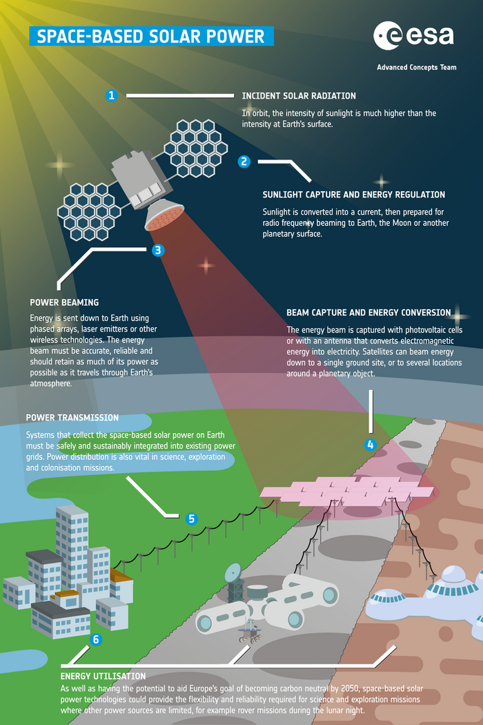
The working principle of Space-based Solar Power is depicted in the below.
This technology transforms solar radiation into energy using the solar panels on a spacecraft, which then wirelessly transmit the energy to a receiving ground station. The captured energy is then converted to electricity before storage and/or distribution.
The large solar array would take advantage of the higher intensity of sunlight outside the planet's atmosphere, as well as unimpeded access to the sun that is unconstrained by the day/night cycle. The electricity is then channeled to a transmitter for long distance wireless transfer via a focused and steerable beam – a key technical challenge. On Earth, the energy would be received and converted back to electricity by the ground station for use.
| Number | Potential Use Cases |
|---|---|
| 1 | Simplify energy delivery to remote areas |
| 2 | Provide more consistent solar power to high latitudes |
| 3 | Provide disaster relief to areas with damaged infrastructure |
| 4 | Recharge other satellites on orbit |
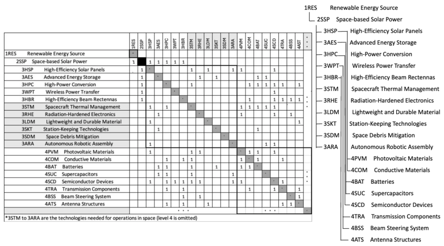
Design Structure Matrix (DSM) Allocation
The 2-SSP tree that we can extract from the DSM above shows us that Space-based Solar Power (2SSP) is part of a larger initiative on renewable energy sources (1RES). It requires the following key enabling technologies at the subsystem level: 3HSP High-Efficiency Solar Panels, 3HPC High-Power Conversion, and 3WPS Wireless Power Transfer (e.g., this includes the management of energy distribution and efficiency). In turn, these technologies require enabling components at level 4, the technology component level: 4PVM Photovoltaic Materials, 4SUC Supercapacitors, 4SCD Semiconductor Devices, and 4ATS Antenna Structures, etc.
[Interdependencies with other roadmaps]
Potentially required for assembly:
[3SB] - Space Booms
Potentially required for assembly:
[3OORR] - On Orbit Refueling and Repositioning
Will aid debris avoidal capability:
[2GREAT] - Ground Based Radar For Space Situational Awareness
Will aid debris avoidal capability:
[4DAA] Detect And Avoid Autonomous Augmentation System
Necessary for reaction control system:
[2SEP] - Space Electric Propulsion
Necessary for spacecraft thermal control
[4VEM] - Variable Emissivity Materials for Spacecraft
Roadmap Model using OPM
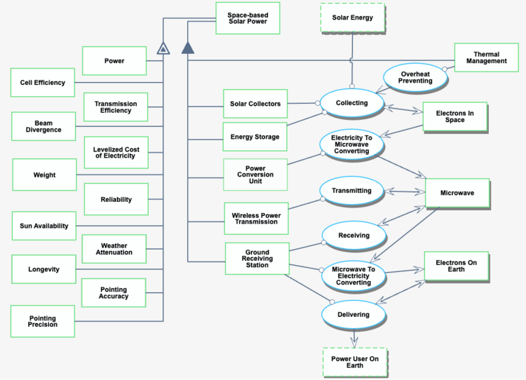
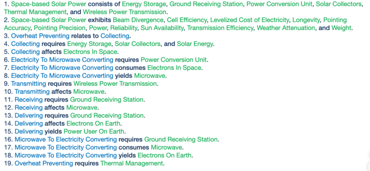
In the figure below, we provide an Object-Process-Diagram (OPD) of the 2SSP roadmap. This diagram captures the main object of the roadmap (Space-based Solar Power), its various instances, including main competitors, its decomposition into subsystems, its characterization by Figures of Merit (FOMs), as well as the main processes (Transmitting, Receiving, etc.).
Figures of Merit
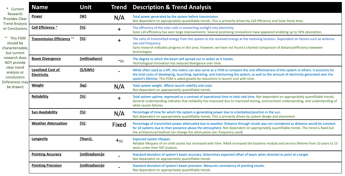
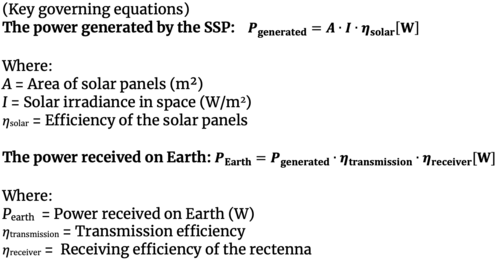
The table below shows a list of FOMs by which space-based solar power can be assessed. The table also contains the FOM trends as well as the key governing equations that underpin the technology.
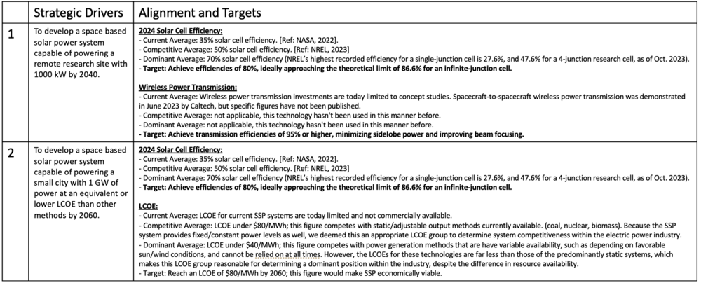
Alignment with "Company" Strategic Drivers : FOM Targets
SSP is designed and developed as a fundamentally disruptive technology, leveraging a combination of advancements in solar cell efficiency, wireless power transmission, space-based construction, and other enabling technologies. To be commercially viable, SSP must demonstrate significant scalability to address large energy demands and be able to significantly reduce cost per unit of energy.
The technology roadmap formulates a set of FOM targets that SSP needs to achieve. These drivers are currently aligned with the SSP technology roadmap.
Positioning of Company vs. Competition: FOM charts
This chart compares the Levelized Cost of Electricity (LCOE) and the Power Output Capacity for various power generation technologies. The X-axis represents the LCOE values in USD per megawatt-hour (MWh), sourced from the U.S. Energy Information Administration (EIA) report[Ref4]. LCOE is a key indicator of the cost-effectiveness of different power generation methods, considering the total lifetime costs divided by the total electricity output over the plant’s operational life. The Y-axis represents the Power Output Capacity in megawatts (MW), which indicates the maximum electrical output that each type of power plant can generate[Ref4-9]. Since the capacity depends on the scale and specific design of each facility, the chart displays a range of typical values as a reference for each technology. These ranges reflect the variety of installations, from smaller local plants to large-scale facilities.
The Roland Berger study for the European Space Agency (ESA) highlights the promising potential of SSP in the future energy market[Ref10]. According to the report, by 2050, the Levelized Cost of Energy (LCOE) for the first operational SBSP system could reach around 69 EUR/MWh ($73/MWh). Additionally, with the learning curve effect, the LCOE might decrease to approximately 49 EUR/MWh ($52/MWh) after deploying the first 10 SSP stations.
This suggests that SSP could achieve a competitive LCOE compared to other power generation technologies.The economic viability of SSP will depend on factors such as climate policy implementation and future energy supply conditions. The study outlines scenarios with electricity prices ranging from 25 to 300 EUR/MWh (~$27 to ~$319/MWh), indicating that SSP could be economically competitive within this range.
Regarding Power Output Capacity, while detailed data is not yet available, SSP’s potential for continuous power generation in space—unaffected by the Earth’s day-night cycle or atmospheric conditions—could lead to significantly higher capacity factors. This continuous generation could enable SSP to achieve substantial and consistent power output, potentially rivaling or surpassing traditional baseload power sources.
Technical Model: Morphological Matrix and Tradespace
The morphological matrix displays the primary technology options available at the initial level of decomposition, as shown in the figure below. Our chosen selections are highlighted in green.
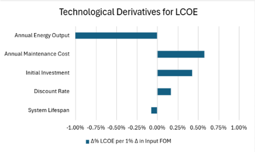
This tornado chart illustrates the sensitivity analysis of the Levelized Cost of Electricity (LCOE). The horizontal axis shows the percentage change in LCOE for a 1% variation in each input Figure of Merit (FOM). The chart reveals that Annual Energy Output has the most significant impact on LCOE, followed by Annual Maintenance Cost and Initial Investment. In contrast, the effects of Discount Rate and System Lifespan are relatively smaller. This analysis helps identify the key factors that can effectively reduce LCOE.
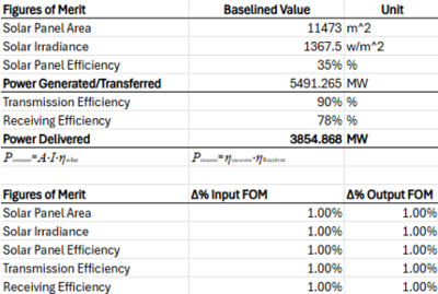
The Tornado chart for the power delivered indicates that the relative performance increases are constant due to the linear formula.
Keys Publication and patents
Key Publication
1. Space-Based Solar Power, Rodgers, E., et al., NASA Office of Technology, Policy, & Strategy, 2024
- The study focuses on the feasibility of a 2-gigawatt SSP system and explores the questions of the mission design (one large system or multiple smaller ones), lifecycle calculations, and performed sensitivity analyses on various factors. The results are summarized in Figure 1. Their conclusions were that the most competitive options used lower launch costs, electric propulsion from LEO to GEO, long service lifetimes, cheaper servicing vehicles, and efficient large-scale production. Although currently estimated to be 12-80 times more costly than terrestrial alternatives, further advancements may make this technology feasible.
- Power beaming was not considered as part of the sensitivity analysis, and is a key technical challenge for SSP. Although demonstrated in June 2023 at Caltech, significant improvements still need to be made for a system of this scale3.
2. A new concept of space solar power satellite, Li X. et al. 2017
- This publication describes a concept for SSP that heavily utilizes ε-near-zero metamaterial to focus sunlight normal to a photovoltaic array as depicted in Figures 1 and 2. The purpose of this is to improve efficiency and reduce the mass of the overall system, which is a major concern due to launch and manufacturing costs when the example system would need a spherical condenser with a diameter of 1.5 km. To reduce the number of systems needed, a geosynchronous orbit is recommended. After focusing the sunlight on the PV array, the generated DC power would be transmitted through a 1km antenna at 5.8 GHz to a 4km diameter rectenna on the ground. An overall concept is depicted in Figure 3.
Patents
A. CPC Classification: H02S 40/22, H02S 40/20, Y02E 10/52
- The patent describes this technology as "a structural substrate body having an array of solar concentrators configured to receive and re-direct solar radiation onto a plurality of photovoltaic (PV) cells". As depicted in Figure 5, this allows a user to reduce the amount of area covered with PV arrays while still capturing the energy from a larger area. Placing the PV cell as depicted in the figure also allows greater efficiencies by not requiring a separate structural support – the reflectors (#103) and PV cells (#104) utilize the same ones.
B. CPC Classification: H04B 7/18513, B64G 1/428; H02S 40/30
- As mentioned earlier in the publication study, sunlight needs to be focused normal to the PV array to achieve the highest efficiency. This patent covers several methods of achieving this in a SSP system using sun sensors in configuration to coordinate turning the tiles for the highest intensity of illumination. A wide number of methods are included such as placing sensors directly on the tiles, orienting them around the area on the spacecraft, receiving signals from other systems (such as GPS), and even smaller sensor spacecraft orbiting the main spacecraft that transforms and beams the energy. A general concept depiction is shown in Figure 6 and the generic process is shown in Figure 7.
References
[1] Pereira, R. A. M., & Carvalho, N. B. (2022). Quasioptics for increasing the beam efficiency of wireless power transfer systems. Scientific Reports, 12(1), 21138. https://doi.org/10.1038/s41598-022-25471-0
[2] NASA. (2023, October 5). New study updates NASA on space-based solar power. NASA. https://www.nasa.gov/organizations/otps/space-based-solar-power-report/
[3] European Space Agency. 2023. Space-based solar power: seeking ideas to make it a reality. ESA. https://www.esa.int/Enabling_Support/Preparing_for_the_Future/Discovery_and_Preparation/Space-based_solar_power_seeking_ideas_to_make_it_a_reality
[4] U.S. Energy Information Administration. (2022, March). Levelized Costs of New Generation Resources in the Annual Energy Outlook 2022. https://www.eia.gov/outlooks/aeo/pdf/electricity_generation.pdf
[5] National Renewable Energy Laboratory. (n.d.). Geothermal Electricity Technology. https://www.nrel.gov/geothermal/geothermal-electricity-technology.html
[6] International Renewable Energy Agency. (n.d.). Renewable Capacity Statistics. https://www.irena.org/Statistics/View-Data-by-Topic/Capacity-and-Generation/Technologies
[7] World Nuclear Association. (n.d.). Nuclear Power in the World Today. https://www.world-nuclear.org/information-library/current-and-future-generation/nuclear-power-in-the-world-today.aspx
[8] U.S. Environmental Protection Agency. (2019). Wind Turbines Fact Sheet. https://www.epa.gov/sites/default/files/2019-08/documents/wind_turbines_fact_sheet_p100il8k.pdf
[9] International Hydropower Association. (n.d.). Hydropower Country Profiles. https://www.hydropower.org/country-profiles
[10] Hader, M., & Hoyer, M. (2022). Space-based solar power: Helping decarbonize Europe and make it more energy resilient thanks to electricity generated in space. Roland Berger. https://www.rolandberger.com/en/Insights/Publications/Space-based-Solar-Power.html
[11] NASA. (2013). Flight Avionics Hardware Roadmap (NASA/TM–2013-217986). https://ntrs.nasa.gov/api/citations/20130013356/downloads/20130013356.pdf
[12] NASA. (2024, January). Space-Based Solar Power: A NASA Technology Assessment. NASA Office of Technology, Policy, and Strategy. https://www.nasa.gov/wp-content/uploads/2024/01/otps-sbsp-report-final-tagged-approved-1-8-24-tagged-v2.pdf
[13] Caltech. (2023, June 1). In a First, Caltech's Space Solar Power Demonstrator Wirelessly Transmits Power in Space. California Institute of Technology. https://www.caltech.edu/about/news/in-a-first-caltechs-space-solar-power-demonstrator-wirelessly-transmits-power-in-space
[14] Li, X., Duan, B., Song, L., Yang, Y., Zhang, Y., & Wang, D. (2017). A new concept of space solar power satellite. Acta Astronautica, 136, 255-264. https://www.sciencedirect.com/science/article/pii/S0094576516311092
[15] Mankins, J. C. (2021). U.S. Patent No. 10,992,253. Washington, DC: U.S. Patent and Trademark Office.
[16] Mankins, J. C. (2019). U.S. Patent No. 10,454,565. Washington, DC: U.S. Patent and Trademark Office.
